
Abstract
Variant selection during displacive transformation is popularly monitored by assessing the pole figure or orientation density function of the bulk texture or pole figures from single prior austenite grains. It can also be done by measuring the physical orientation of α′ (bainite or marteniste) plates in the microstructure. It is known that when variants of α′ form randomly, i.e. there is no variant selection, the shear strain associated with each α′ plate gets canceled and transformation strain becomes equal to the volume strain. Under this condition, orientation of sheaves of α′ also shows random distribution. In this work, it has been shown how transformation strain and orientation of sheaves change when variant selection occurs. Mathematical models have already been developed to calculate the transformation strain under various loading conditions; extensive experiments have been conducted during the course of this work to show how the nature of externally applied stress influences the transformation strain. In addition to this, it has also been shown that the variant selection might leave its trace in the microstructure by affecting the alignment of the sheaves under externally applied stress and strain. Mathematical models have been developed to show that variant selection has negligible influence on physical orientation of α′ plates when transformation occurs under external stress, but prior plastic deformation can dictate the orientation to a great extent.
Keywords
Introduction
The requirement for steels with high strength and elongation is increasing day by day. Displacive transformation in some classes of steels aids to the overall strain and hence enhances ductility. Therefore, research in the area of variant selection and its effect on transformation strain might help in developing new grades of steels with higher ductility. It has been discussed in sufficient detail in recent literature that when bainite or marteniste transformation occurs under the influence of stress or strain, some variants are favoured, this phenomenon is known as variant selection.1–5 The variant selection during martensitic/bainite transformation leaves its mark in two ways. First, it might change the microstructure with more and more sheaves of α′ aligned to a particular angle with the stress axis and second, it changes the transformation strain to a significant extent. Hase et al. 6 showed that bainite transformation under stress changes the alignment of sheaves, and the same has been shown by Matsuzaki et al. 7 Along with the positive effects from transformation strain, variant selection might also make the bainite/martensite sheaves aligned in one or more preferred directions, which might create easy path for crack growth. Therefore, transformation strain and sheaf alignment due to variant selection need to be studied together.
Hase et al. 6 have shown that when bainite transformation takes place under compressive stress, transformation strain increases significantly. Later, Kundu et al. 8 have shown through mathematical modelling that not only stress affected bainite transformation increases the transformation strain, but also the nature of transformation strain changes with the type of externally applied stress (compressive or tensile). However, so far, there is no experimental evidence found in the literature which confirms the changing nature of transformation strain under compressive and tensile stresses. In this paper, experimental evidence has been presented to show that indeed the nature of externally applied stress changes the nature of transformation strain. Although some experimental evidence of alignment of the sheaves of bainite has been shown in the literature, mathematical models already suggested 9 that alignment of bainite sheaves under externally applied stress could be difficult to achieve unless variant selection is extraordinarily strong.
Several approaches have been undertaken to predict variant selection under plastic strain.10–14 Haslam et al. 11 employed Bishop–Hills crystal plasticity analysis and considered martensite nucleation on (1) the most active slip system, (2) all active slip systems, (3) the most active slip plane and (4) all the active slip planes. Based on these assumptions, they predicted transformation texture reasonably well. Bokros and Parker 10 and Durlu and Christian 12 related habit plane of the variants and active slip systems. Malet et al. 14 also found a strong correlation between variant selection and plane of maximum slip activity. These observations suggest that the alignment of sheaves could be related to the plane of maximum shear. An effort has been made towards this direction in the current work to explain the alignment of sheaves of bainite under plastic strain.
In this paper, careful experiments have been conducted to understand the nature and extent of sheaf alignment under different types of external stress and strain. It has been shown that the nature of sheaf alignment changes with applied stress or strain. The typical nature of sheaf alignment under various degrees of variant selection has been explained with the help of mathematical model.
Experimental
A bainitic steel having composition Fe–0·79C–1·56Si–1·98Mn–1·01Al–1·1Cr–1·0Co–0·24Mo has been used for experiments. Bainitic transformation in this steel has been induced under stress and strain as shown in Fig. 1 6 using Gleeble thermomechanical simulator. Bainite has been induced in the samples at 300°C under tensile and compressive load, which is kept just below the yield strength of the material. In one sample, bainite transformation is also induced without the influence of any external load. To study the alignment of the sheaves under plastic strain, bainite transformation has also been induced in austenite, which is plastically deformed above the Bs temperature (400°C). After that, the samples are properly polished in colloidal silica solution and electron backscatter diffraction (EBSD) analyses are carried out on all samples in a Zeol FEG SEM with step size of 0·5 μm. The data obtained have been analysed with the help of Channel 5 software. Pole figure of bainite (α′) is obtained from various grains of austenite. Samples where bainite transformation is induced without any external load is named as ‘SB noload’. Similarly samples under compressive load, tensile load and plastic strain are named as ‘SB comload’, ‘SB tenload’ and ‘SB strain’ respectively. The applied stresses for specimen ‘SB comload’ and ‘SB tenload’ are 200 MPa (compressive) and 210 MPa (tensile), respectively. Specimen ‘SB strain’ was subjected to a strain of 3·5.
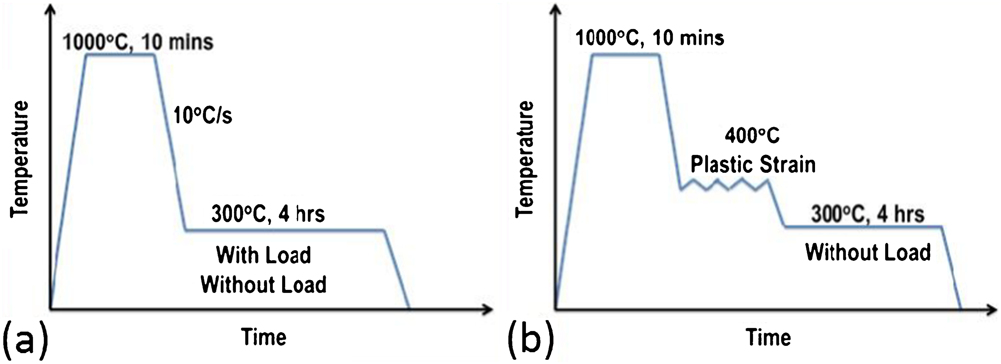
a thermal cycle by which bainite transformation is induced in stressed austenite and b thermal cycle by which bainite transformation is induced in plastically deformed austenite
Apart from EBSD analysis, optical microstructure has also been observed after etching the samples in nital and the same has been further analysed to quantitatively determine the alignment of sheaves with respect to the direction of applied stress.
Quantitative determination of variants in microstructure
There are 24 variants of bainite that can form in any alloy system. The orientations of all these variants have a fixed orientation relationship (OR) with the prior austenite grain, which can be determined using the Phenomenological Theory of Martensite Crystallography (PTMC).15,16 As the orientation of austenite grain changes, the orientations for all 24 variants are also expected to change. This can be determined following this equation
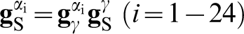
 represents the orientation of γ grain in the microstructure which can be obtained from EBSD data,
  represents the ideal OR between γ and α′ which can be determined using PTMC.
17
It is understood that there are 24 such matrices, which describe the OR for 24 variants.
represents the ideal OR between γ and α′ which can be determined using PTMC.
17
It is understood that there are 24 such matrices, which describe the OR for 24 variants.  gives the actual orientation of 24 variants of α′ in the reference frame of sample that originates from one prior austenite grain.
The next important step is the determination of volume fraction of each variant within one prior austenite grain. This is done in the following way. First, the EBSD data from one prior austenite grain is separated and the average austenite orientation is determined. With the help of this and following equation (1), it is possible to determine the expected orientations of 24 bainite variants in any prior austenite grain. To determine the volume fraction of variants quantitatively, each EBSD data point is analysed. Each point of EBSD data file gives the orientation of that point, let's say this is gA for any point A. The next step is to find which of the 24 variants this point belongs to. As we already know, the 24 possible orientations of variants form any particular prior austenite grain using equation (1); we can take this orientation as  . The misorientation between ‘A’ and ‘Vi’ can be determined using the following equation
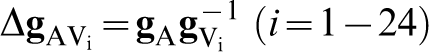
In this way, 24 axis–angle pairs representing the misorientation between any point in the EBSD data file are obtained with 24 possible variants for a particular prior austenite grain. However, the point ‘A’ is assigned to that variant with which it has the minimum misorientation angle. In this way, all the points from one EBSD map have been analysed and assigned to one of the 24 variants, this gives a clear quantitative distribution of all the variants formed within one prior austenite grain. The whole process is depicted in Fig. 2. The fraction of data points belonging to a particular variant over the total number of data points is taken as the volume fraction of that variant.
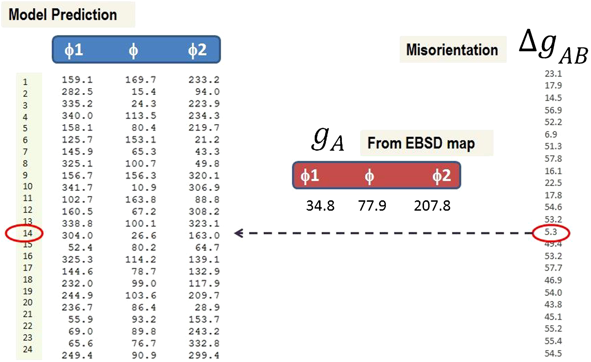
Methodology for identification of variants
Why Patel–Cohen theory works well in Bain groups
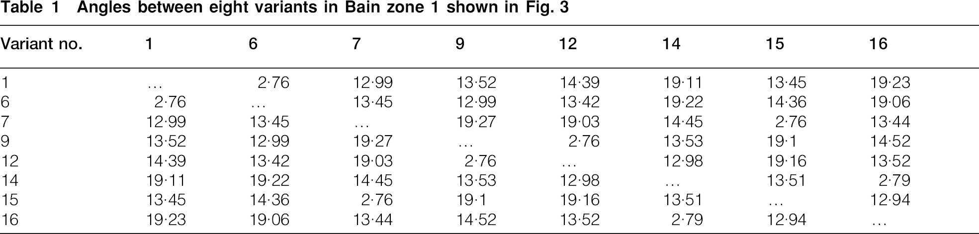
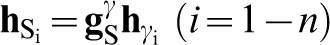
In previous work, Kundu et al.2,3,8 have shown that Patel and Cohen's 18 theory can be applied well for predicting variant selection for bainite transformation under stress. These studies indicate that generation of mechanical free energy due to external stress influences variant selection and variants having higher mechanical free energy have better chances of formation. However, in a more recent work, Kundu et al. 1 have shown that Patel and Cohen's theory works well for polycrystalline materials, but in individual grain level, it does not. It indicates that all variants with higher mechanical free energy may not have higher volume fraction. In order to explain the same, Kundu et al. 1 have studied the microstructural features of bainite transformation in detail and explained how some variants would not form in higher volume fraction, even if the mechanical free energy associated with those variants is high, because of the physical location of their nuclei. They have also explained that a better prediction using the Patel and Cohen's theory can be achieved if the variants are distributed into three different Bain groups. Figure 3 shows the result of a similar analysis from this study using sample ‘SB tenload’. Figure 3a shows the interaction energy and volume fraction of 24 variants from one prior austenite grain. It is clear from this plot that volume fraction and interaction energy cannot be correlated to the level of individual variants. However, when these are segregated into three Bain groups, the interaction energy and volume fraction of variants have very good correlation (Fig. 3b). It can also be found that within one Bain group, the volume fraction of individual variants has much better correlation with their respective interaction energies (Fig. 3c). We have done further analysis to understand why the Bain groups give better correlation in terms of their interaction energies than the individual variants. The analysis presented in Fig. 3 indicates that the eight variants within each Bain group behave in a manner as if they are a single entity. In order to understand the reason behind this, the misorientation angles between them were calculated. It has been found that the misorientation angles between variants within any Bain zone are low, which is shown in Table 1 for a particular Bain zone. From this table, it is clear that the maximum misorientation between any two variants within a Bain zone is 19·27° and 70 of the misorientation angles is below 15°. Therefore, it can be said that within one Bain zone, the variants are almost parallel. It is obvious that the parallel plates of Bainte would show much less tendency of hard impingement and will be able to grow uninterrupted by the presence of other variants. This makes the variants within one Bain zone to grow together within a prior austenite grain. Of course, there is competition between three Bain zones and the Bain zone having higher interaction energy have higher volume fraction. Again within one Bain zone, it is expected that the variant with higher interaction energy will have higher volume fraction unless their growth is interrupted due other microstructural features described in Ref. 1.
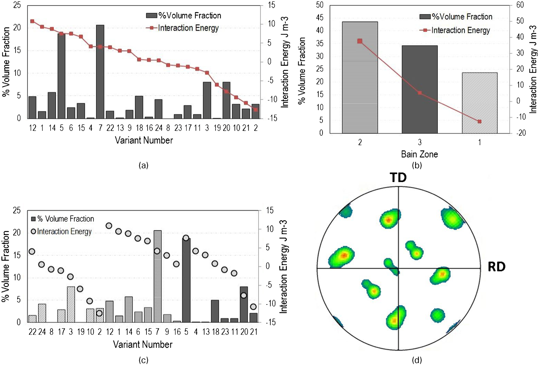
a volume fraction of 24 bainite variants and their interaction energies formed within one prior austenite grain, b volume fraction of variants in three Bain zones along with their interaction energies, c volume fraction of individual variants along with their interaction energies within three Bain zones and d EBSD map of bainite from single prior austenite grain
Angles between eight variants in Bain zone 1 shown in Fig. 3
Alignment of bainite sheaves towards the direction of applied stress
For the samples ‘SB noload’, ‘SB comload’, ‘SB tenload’ and ‘SB strain’, quantitative metallographic examination has been done in order to determine the volume fraction of bainite sheaves aligned towards the direction of applied stress. Previously, Hase et al.
6
showed that when bainite transformation takes place under the influence of large externally applied stress (stress close to yield strength of the material), there is a tendency of the sheaves to be aligned at an angle of 45° with the direction of applied stress. However, Kundu et al.
9
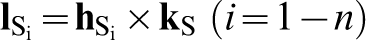
have shown using mathematical model that if the sheaves of bainite have to align at 45°, a very high level of variant selection would be necessary (typically two to three variants should form out of total 24). That high level of variant selection is hard to achieve in this material. The prediction of angle between the trace of habit plane with the direction of loading is done in the following way. To find out the angle between the habit plane and the direction of stress, first, the trace of habit plane on the plane of observation is determined. It can be done by taking the cross-product between the unit plane normals of the habit plane and the plane of observation. The resultant vector gives the traces of the habit planes on the plane of observation. In order to do that, first, the habit plane normal is expressed in the reference frame of the sample:
And then the cross-product is taken.
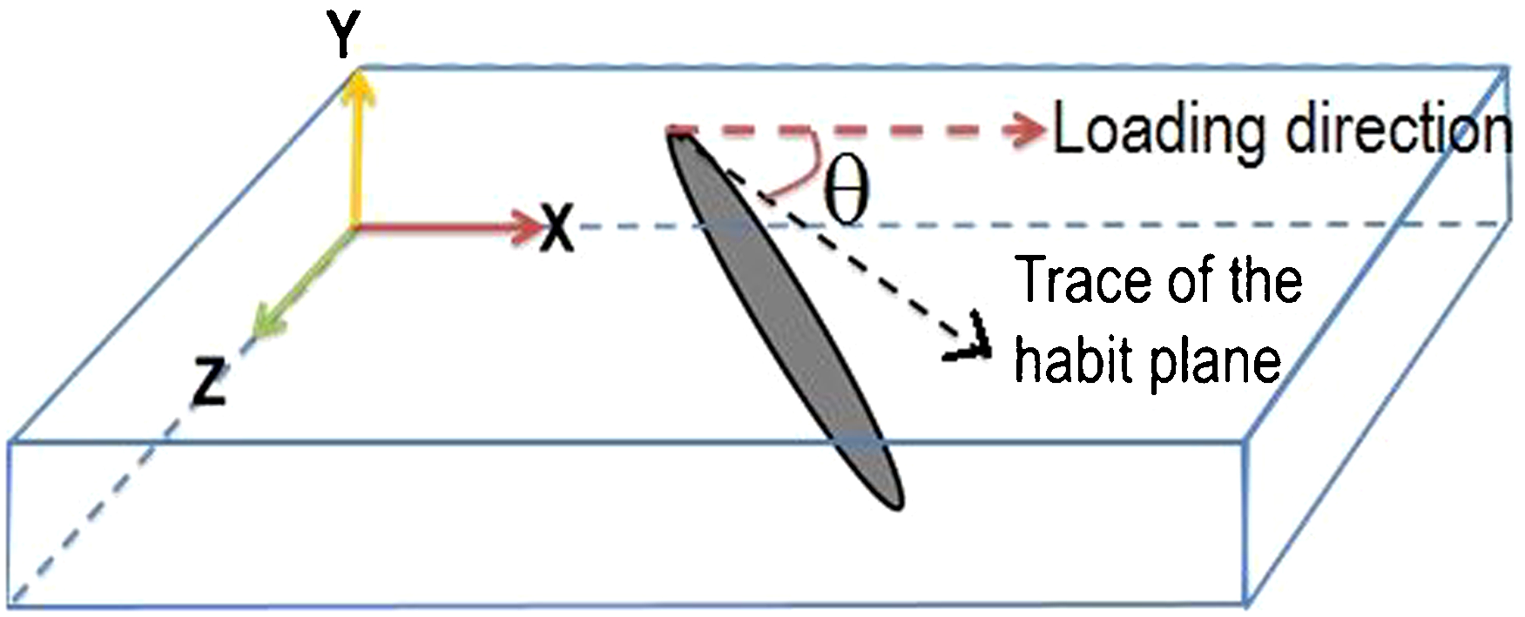
Angle between trace of habit plane with loading direction.
Distribution of angle made by the traces of habit plane of bainite plates formed from austenite under tensile stress with the stress axis is shown in Fig. 5. It is easily understood from this figure that a sharp distribution with a peak at 45° is possible if only two variants amongst 24 variants form in the microstructure (Fig. 5a). However, as the number of variants increases, the sharpness of distribution decreases. It has been shown in Fig. 5b that if eight most energetically favoured variants form in the microstructure, it gives a very weak peak at about 55° to the direction of loading.
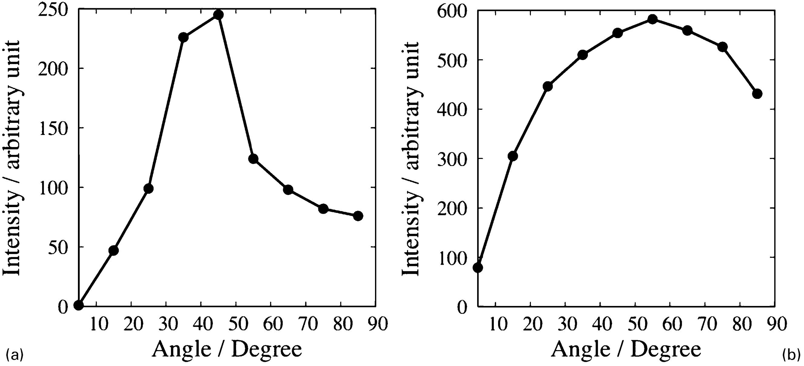
a two most favoured variants; b eight most favoured variants
Figure 6 shows the distribution of bainite sheaves under the influence of different types of stress and strain. It is obvious from this figure that when bainite forms under no influence of stress, the sheaves are aligned randomly. The same has been observed for the variants formed under compressive load. However, for bainite formed under tensile stress, there is a weak maxima at an angle of 60° similar to what has been predicted (Fig. 5b).
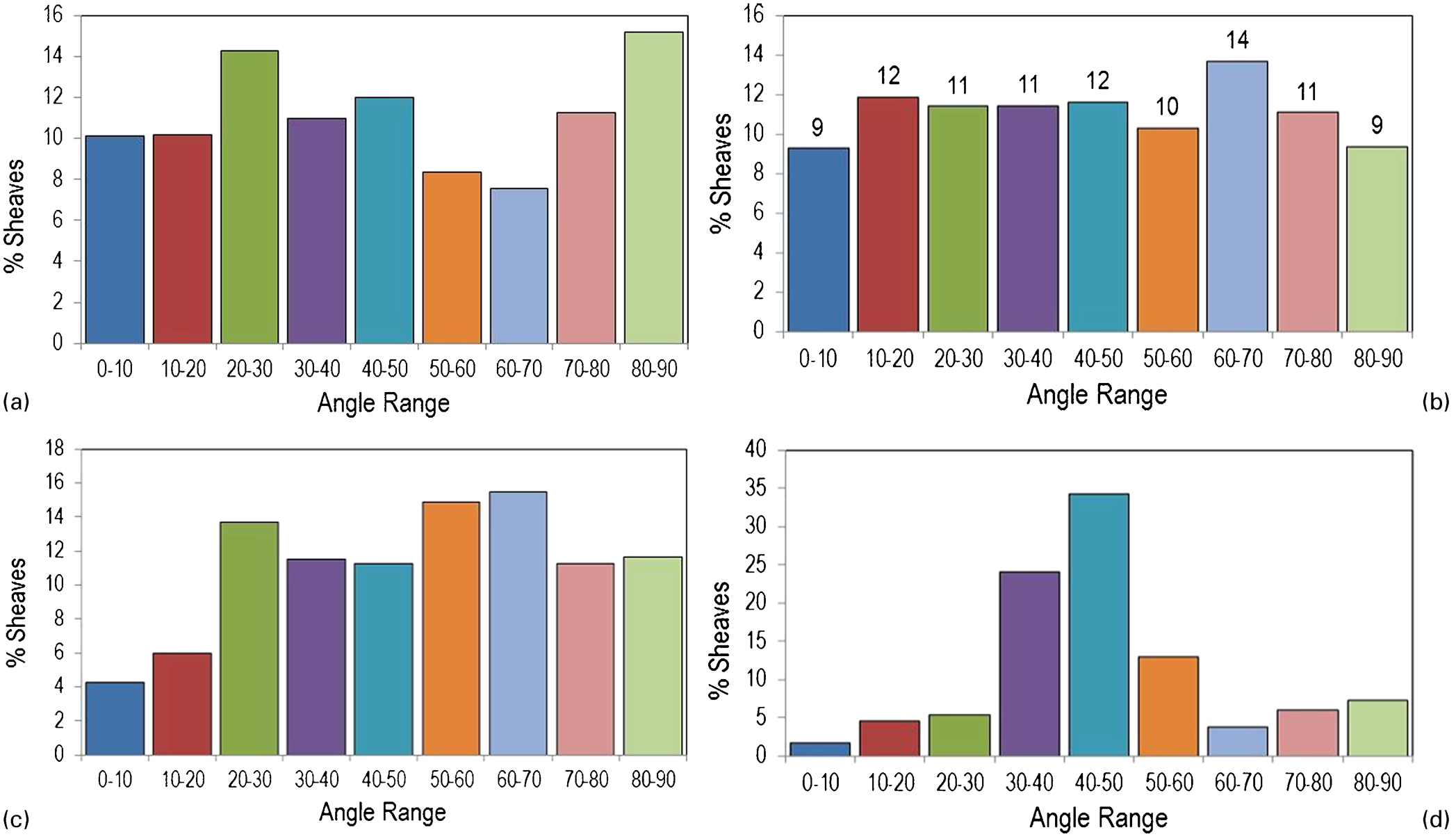
Experimentally determined distribution of bainite sheaves with respect to loading axes: this is done under four conditions, when banite forms a under no stress, b under compressive stress, c under tensile stress and d from plastically deformed austenite
It can be seen from Fig. 6d that under strain, bainite sheaves have a tendency to be aligned to 45° to the axis of loading. In fact, the distribution is much prominent than what is found in bainite transforming under any kind of stress. This result clearly indicates that the tendency of variants to be aligned in one particular direction is most prominent when transformation occurs under plastic strain. It is known that under plastic strain, austenite will deform and depending on the orientation of various slip systems with respect to the loading axis, some will be more active than others. As mentioned earlier, a strong correlation has been observed between the selected variants and slip system activity.10–14 Hence, finite element simulations were carried out using single crystal plasticity to determine the plane of maximum slip activity and relate it to the sheaf alignment. The finite element procedure is based on the formulation proposed by Asaro 19 and was implemented as described by Biswas et al. 20 A tensile loading was applied along the rolling direction. A set of 1000 random austenite orientations were considered and the slip plane with maximum shear was identified from the simulation for each orientation. The angle between the axis of loading and the trace of the plane of maximum shear was determined following the same procedure described earlier for each orientation. The distribution of these angles is shown in Fig. 7. The model clearly predicts that the most active slip planes in austenite under tensile strain tend to align at an angle of 45°. The similarity in alignment between bainite sheaves and active slip planes (Figs. 6d and 7) clearly indicates that in strained austenite, variant selection has close relationship with the active slip planes.
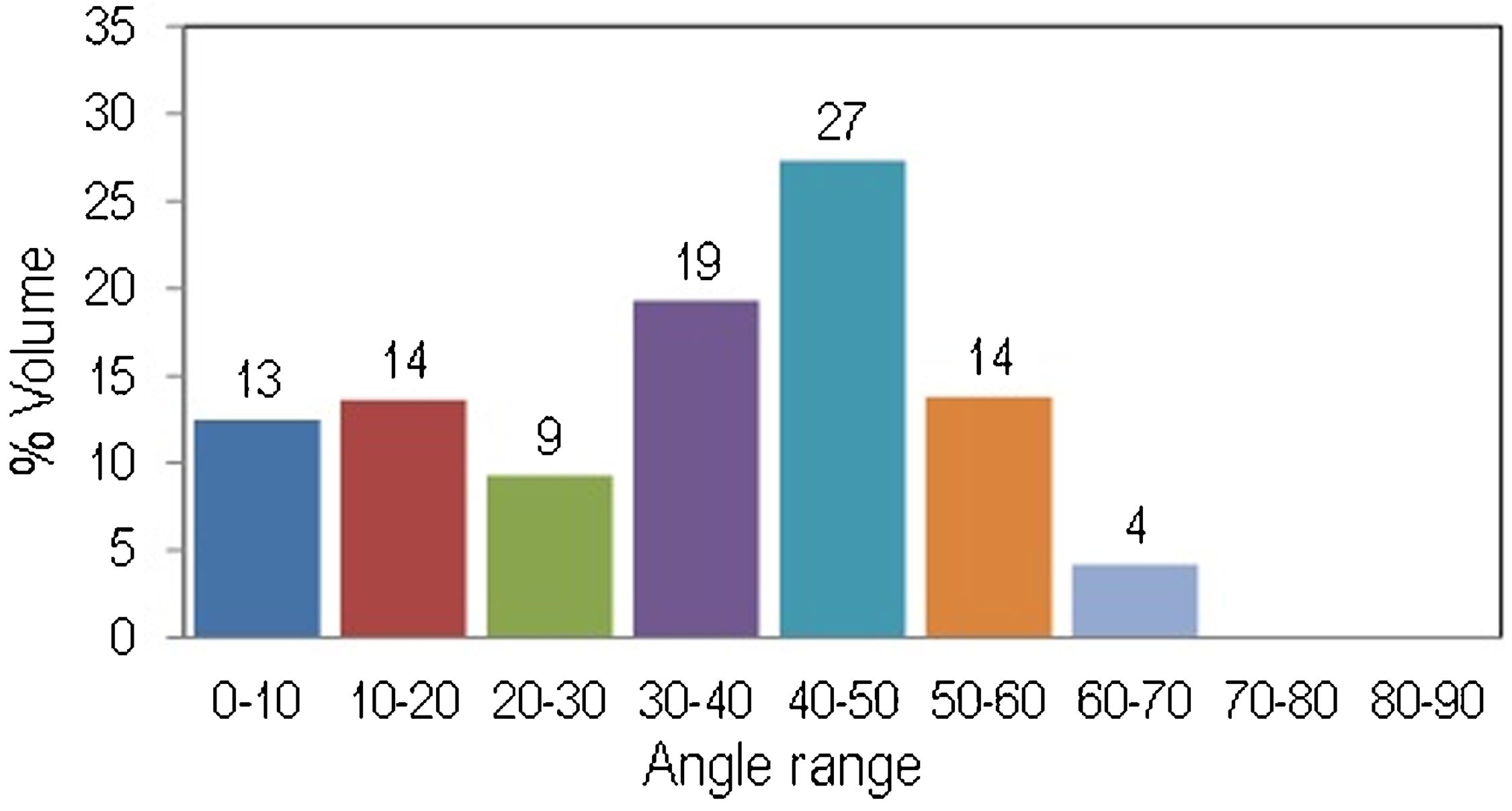
Distribution of most active slip planes with respect to loading axis
Comparing the microstructure of the stress affected and strain induced bainite with the bainite formed without any external influence, it is clear that the appearance of these three, apart from their alignment differences as described earlier, is very distinct (Fig. 8). The bainite sheaves formed under tensile stress seem to be fatter than the one formed without stress as shown in Fig. 8b. The same has also been reported by Hase et al.. 6 Owing to variant selection, bainite sheaves belonging to one Bain zone tend to grow together and experience less hard impingement effect from other adjacent variants. It has already been described that the sheaves within one Bain zone have lower misorientation between them. As a result, variants formed under tensile stress can experience more side-wise growth and appear to be wider. In the case of ‘SB noload’ and ‘SB tenload’ samples where bainite formed without any load and with tensile stress (micrographs shown in Fig. 8a and b respectively), the amount of bainite has been measured using XRD and the amounts are 65 and 60 respectively.
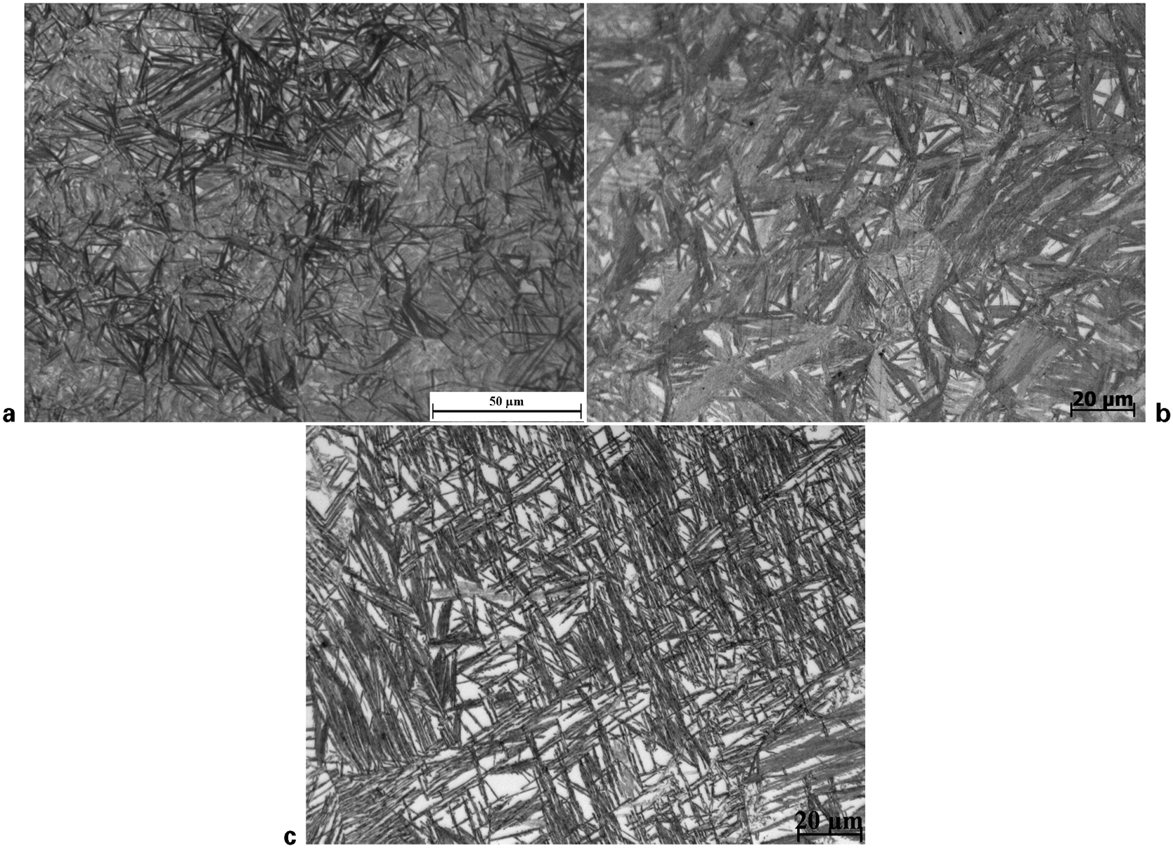
Microstructure of bainite formed under a no external load, b under tensile load for sample ‘SB tenload’ and c under plastic strain ‘SB strain’
The appearance of the sheaves formed under plastic strain is completely different. In this case, the sheaves look slender and sharp, as shown in Fig. 8c. This is because of the fact that due to plastic deformation in austenite, dislocations pile up and hinder the movement of the glissile interface of bainite. The theory behind it is described by Chatterjee et al.. 21 As the movement of the glissile interface is hindered, the sidewise growth of the bainite sheaves also becomes difficult, which makes the bainite appear slender. The other effect of deformation of austenite on transformation is the mechanical stabilisation and the reduced level of phase transformation. As the growth of bainite becomes difficult in this case, the total amount of bainite has been measured (using XRD) to be 45, which is approximately 20 less than what is obtained in samples where bainite transformation took place from undeformed austenite. This is the result of mechanical stabilisatuon of austenite due to plastic deformation. Further, the degree of variant selection was invesigated using detailed EBSD analysis for several prior austanite grains in the sample ‘SB strain’. The same has been presented in Fig. 9 for two such grains. A strong variant selection can be observed from this figure where prominently only three variants have been selected.
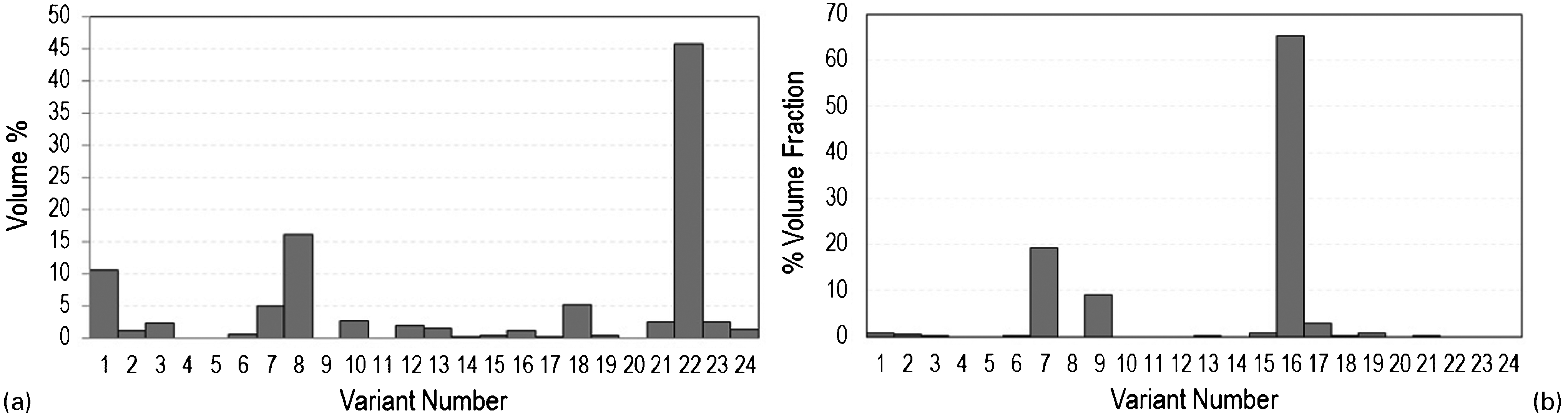
Volume fractions of 24 bainite variants under plastic strain in a prior austenite grain 1 and b prior austenite grain 2
Transformation strain under various kinds of stress
Variant selection during bainite transformation also generates transformation strain, the origin of which is in the shear strain associated with any displacive transformation (bainite or marteniste). The transformation strain depends on the amount of phase fraction, alloy content and extent of variant selection. Kundu et al.
8
have already shown using suitable mathematical models that transformation strain can be predicted using the following method. Consider an arbitrary vector 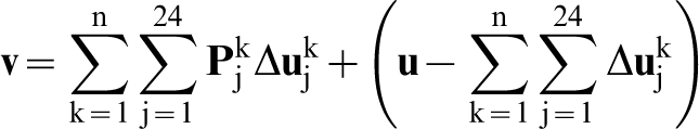
 can be approximated by
  where
where  is the fraction of sample transformed by variant j in austenite grain k. The transformation strain is calculated as ln (|
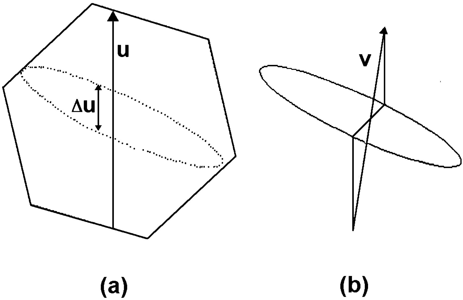
a austenite grain before transformation, with ultimate location of plate of bainite marked; b following bainitic transformation 22
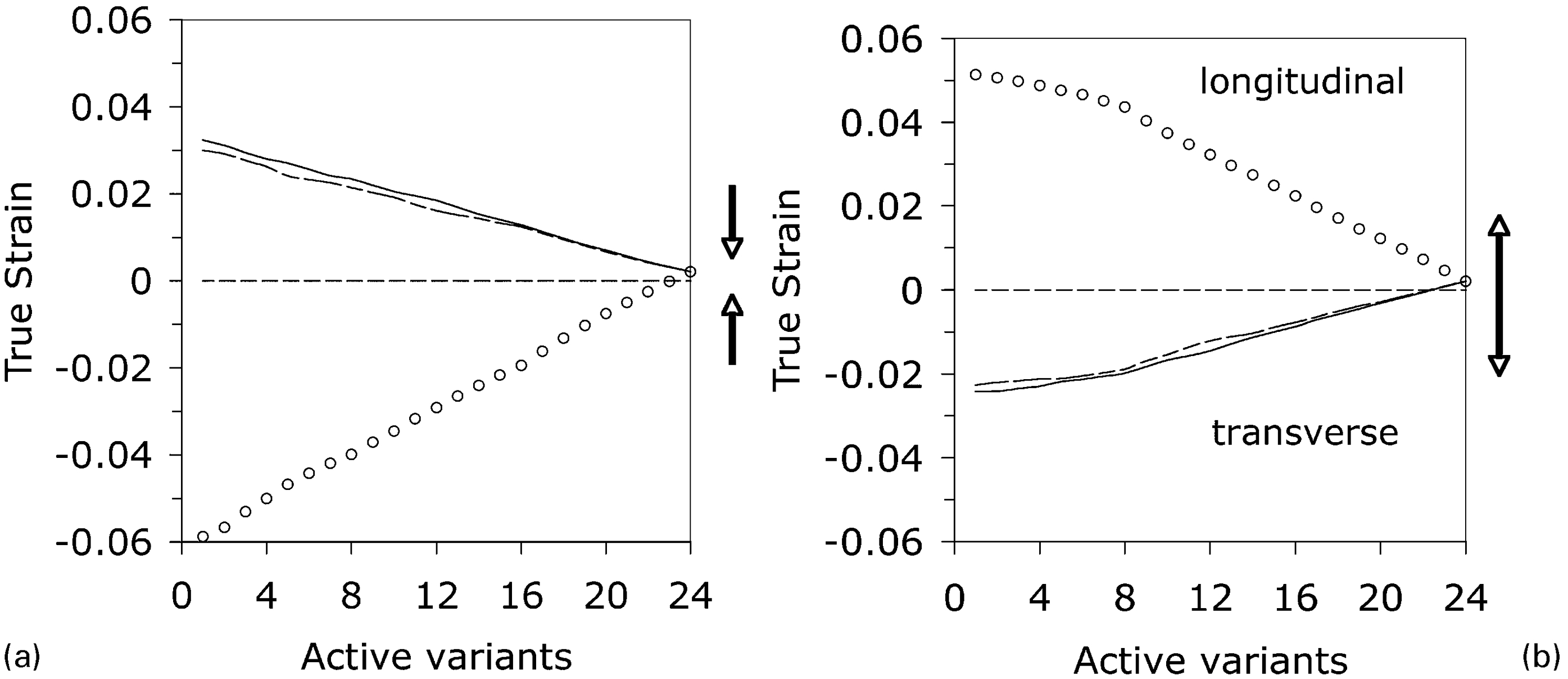
Model predicted transformation strain in bainitic steel a under compressive load for sample ‘SB comload’ and b under tensile load for sample ‘SB tenload’ 22
It is known that each bainite or martensite plate has two kinds of strains associated with it. The first one is a volume strain and the second is a shear strain. When many variants of bainite or martensite form randomly in a prior austenite grain, the shear strain gets canceled, but the volume strain remains.8,22 Under that situation, transformation strain becomes equal to the volume strain. However, with strong variant selection, shear strains associated with variants do not get canceled completely, resulting in an increase in transformation strain. Calculations done following equation (5) reveals (Fig. 11) that the maximum transformation strain in the transverse direction in a polycrystalline bainitic steel as studied here would be around 0·03, which is much smaller than the shear strain associated with each plate (0·22). There are some more interesting facts about the transformation strain apart from their sign (compressive or tensile). It can be seen from Fig. 11 that the strain in the longitudinal direction is always higher than in the transverse direction. Another interesting fact is that the transformation strain is higher under compressive stress than tensile stress. Although the reason for this is not very obvious, it might have its origin in the Bain strain, which is an integral part of the strain associated with martensite. However, as the Bain strain has never been determined experimentally, it is difficult to prove that the transformation strain is actually affected by the Bian strain.
Experimentally determined transformation strain under tensile and compressive load are shown in Fig. 12. Figure 12a shows the transformation strain for ‘SB noload’. As in the ‘SB noload’ sample, the bainite transformation takes place without the influence of any external stress, variants form randomly and only the volume strain remains as the total transformation strain. It is to be mentioned here that the total volume strain associated with each bainite plate for this material as calculated using the PTMC is 0·009. However, as the strain is measured in the transverse direction, the expected strain would be only one-third of the theoretical strain. In addition to that, if we consider the amount of bainite in the microstructure, which is approximately 60, the transformation would be about 0·002. It is shown in Fig. 12a that the experimental strain obtained under no stress conditon matches with this theoretical value. Under compressive stress, the transformation strain is 0·014, which indicates on an average 12–13 variants have formed in this sample (Fig. 12b). The transformation strain for tensile stress is about 0·017. Comparing with the theoretical prediction, it can be said that in this sample, on an average 9–10 variants have formed in each prior austenite grain (Fig. 12c) under tensile stress.
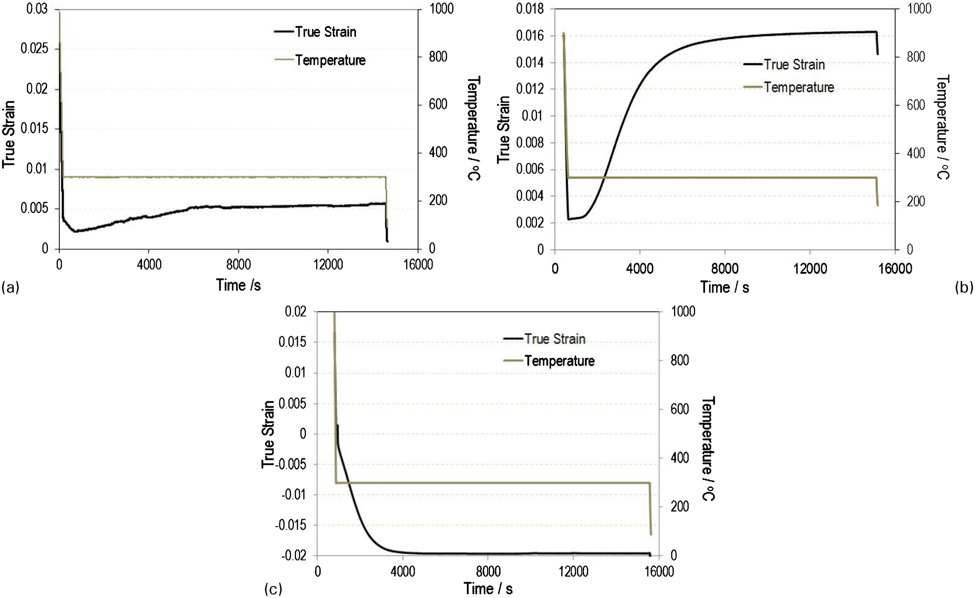
Experimental transformation strain in bainitic steel a under no external load for sample ‘SB noload’, b under compressive load for sample ‘SB comload’ and c under tensile load for sample ‘SB tenload’
Conclusion
Effect of variant selection under external stress and strain has been discussed with the help of mathematical model and experiments.
It has been shown that variant selection affects the distribution of sheaves in the microstructure; however, alignment of sheaves is not prominent. It has been shown with the help of mathematical model that the bainite sheaves can be aligned to an angle of 45° with the applied stress axis only if very high level of variant selection takes place.
It has been shown that with the weaker variant selection, the angle of alignment of variants with the stress axis becomes random, also the angle at which most of the variants lie, changes to higher values.
Transformation strain is affected due to variant selection the most. At lower level of variant, selection transformation strain is less and vise versa.
Nature of transformation strain changes with the nature of externally applied stress. Bainite transformed under compressive stress generates positive transformation strain in the transverse direction; however, bainite formed under tensile stress develops negative transformation strain.
It has been found that the transformation strain is low in the transverse direction when comparing the same in the longitudinal direction. It has also been found that the absolute value of transformation strain is higher when bainite transforms under compressive stress than tensile stress. The reason behind this could be the influence of Bain strain; however, this cannot be proved with the present state of understanding of the PTMC.
Footnotes
Acknowledgements
The authors of this paper gratefully acknowledge the encouragement and funding provided by the management of Research and Development Division of Tata Steel, India, for this work. The authors would also like to acknowledge Ms I. Mohanty of R&D division of Tata Steel for her help with the computer program used in this work.