
Abstract
Use of transvaginal ultrasonography for cervical length measurement at the 20-week anatomic examination has been suggested as a screening method to predict the risk of preterm birth. This article describes a three-dimensional ultrasonographic multiplanar imaging method of cervical length measurement by manipulating the center reference point and volume axes. This methodology should yield a more consistent, accurate measurement of the cervical length compared to conventional two-dimensional ultrasonographic methods. Also described are additional software image manipulation techniques to enhance visualization of the relational anatomy of the cervix. Precise utilization of the center reference point and available image reconstruction software augment current two-dimensional morphologic information of the lower genital tract.
Keywords
Introduction
The initial nomograms utilizing two-dimensional (2D) transvaginal ultrasonography of the pregnant cervical length were established in 1990.1,2 These served as a baseline for our ability to compare the normalcy of the singleton pregnant cervix and those shortened or abnormal. The transvaginal ultrasonographic (TVU) approach has become the standard in the evaluation of the cervix during gestation and is recommended instead of a transabdominal approach. 3 Additionally, applying routine cervical length measurement at the 20-week anatomic examination has been suggested as a screening method to predict the risk of preterm birth, followed by offering medical progesterone treatment when shortened. 4
The aim of this article is to provide a step-by-step description of the methodology to precisely reconstruct and assess cervical length using three-dimensional (3D) ultrasonography. A literature search and evaluation showed that articles and imaging legends describing 3D cervical length imaging did not include use of the center reference point (CRP) on the volume set. Inclusion of this central step is paramount in qualitative and quantitative 3D assessment. The article describes a method of cervical length measurement using 3D ultrasonographic multiplanar imaging by manipulating the CRP and volume axes. This methodology should yield a more consistent, accurate measurement of the cervical length. Additionally, the use of commercially available image reconstruction software (e.g., OMNI View, GE Healthcare, Zipf, Austria) can enhance visualization of the relational anatomy of the cervix, whether normal or sharply curved.
Methodology
Normal Cervix
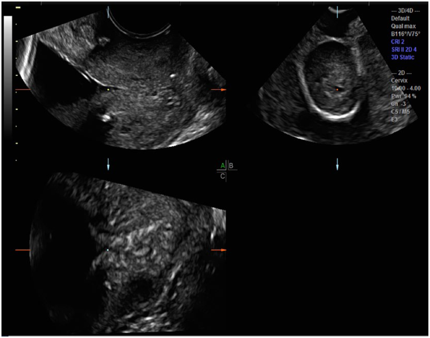
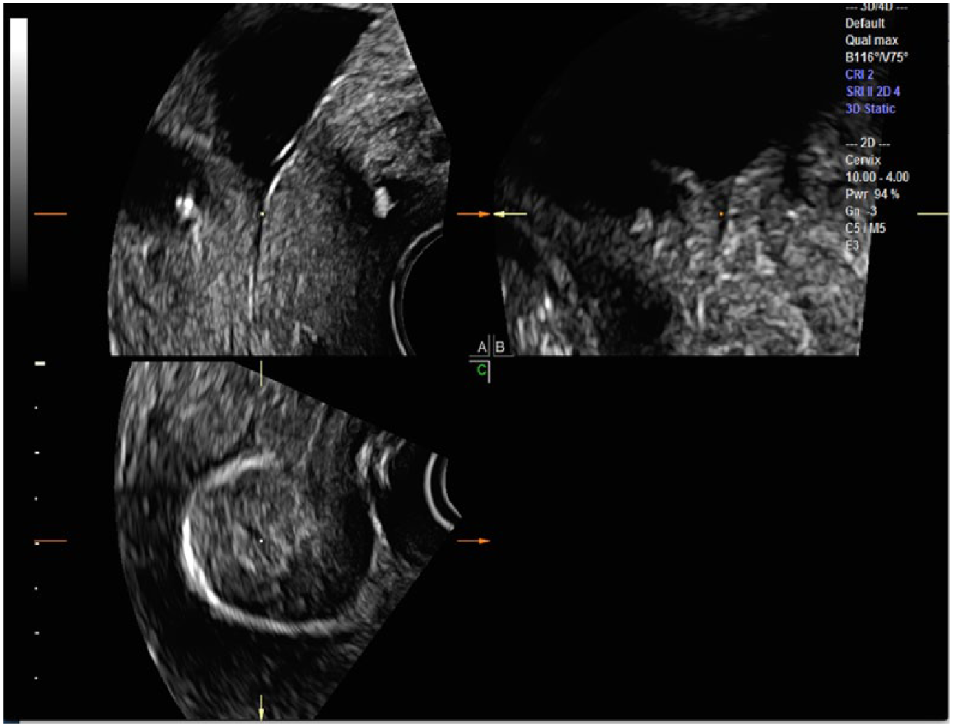
All cases were examined using an E8 ultrasound system (GE Ultrasound, Waukesha, Wisconsin, USA) with the 5 to 9 MHz endovaginal transducer. The acquisition plane for creating a 3D cervical length volume set is universally obtained in the midline sagittal plane (A plane), and the 3D volume set of all three orthogonal planes of the cervix before any manipulation of the image is shown in Figure 1. Thus, the A plane will be midline sagittal, the B plane will be transverse, and the C plane will be a coronal cut through the area of interest (AOI). The 3D volume sweep will automatically place a CRP in the middle of the anatomy around which the sweep is made. This will be seen in the center of all three orthogonal plane images either as a point or cross bars on the screen. 5 Note that the centrally located CRP in the middle of all three images is not at the AOI. If the CRP is moved directly anteriorly to the middle of the cervix on the A plane, it will move to that same location on all three planes. This will help fine-tune the appearance of any specific location. Additionally, moving the CRP to the center of the cervix on the B and C planes will align the midline more precisely on the A plane. The CRP should then be moved to the most proximal (superior) midpoint of the internal os on the C plane (Figure 2). Additionally crucial to precise manipulation of the volume set is the necessity to alter the X, Y, and Z axes to further refine the volume set morphology. This refinement is dependent on what the examiner wants to emphasize simultaneously on all three planes.5,6 For example, shifting the C plane on the Z axis will result in a correction of the cervical length (CL) on the A plane, and rotating the Y axis on the A plane will elongate the cervical length.
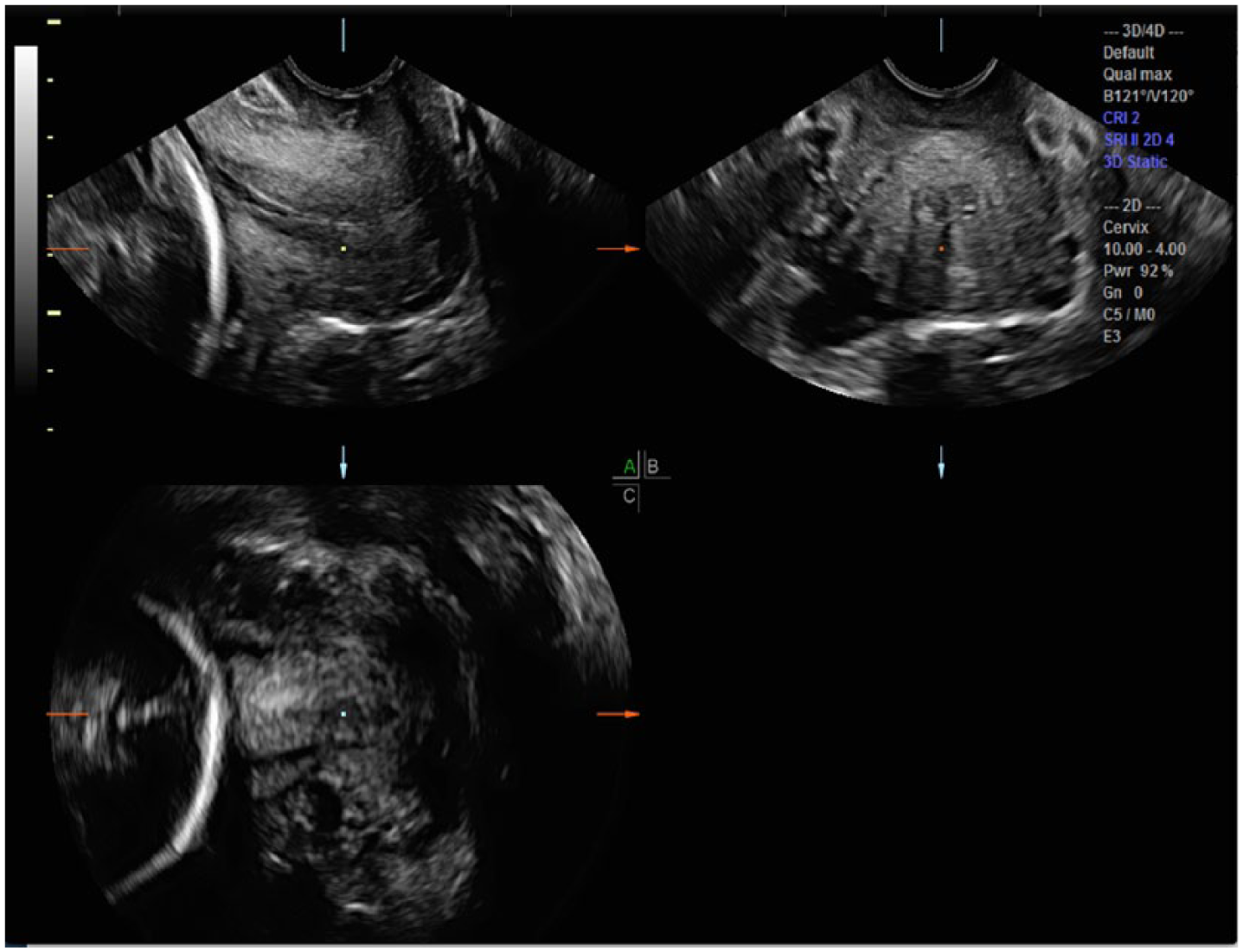
Initial three-dimensional volume sweep places the center reference point (CRP; square dot) in the middle of all images, prior to being moved to the area of interest (AOI) on all three planes.
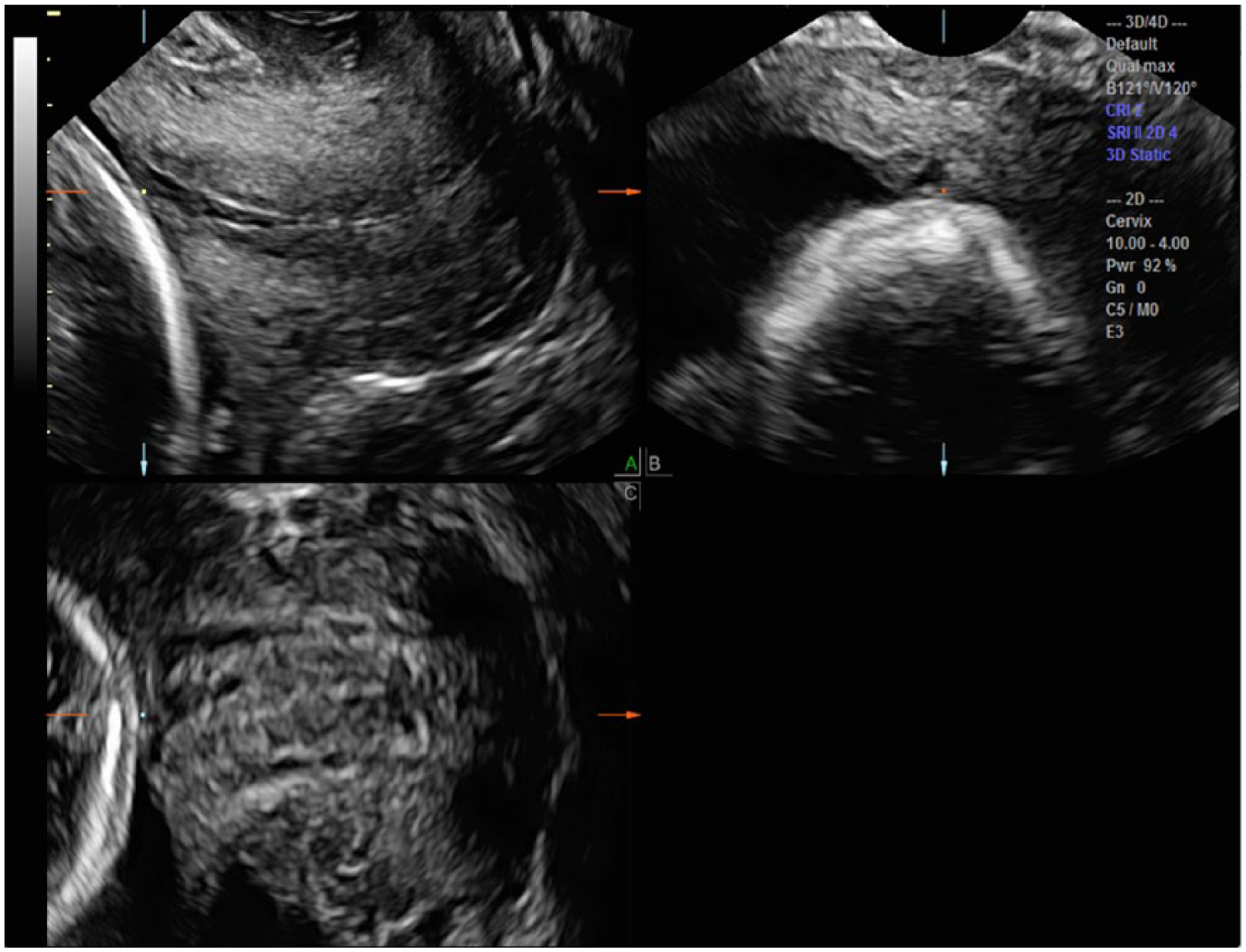
To best measure the cervical length (cl), the center reference point (CRP; square dot) is placed at the most superior aspect of the apposing aspects of the cervix in the A plane. Further adjustment of the CRP to the center of the internal os on the C plane and the B plane allow the appropriate location for measuring the CL on the A plane.
Cervical Funneling
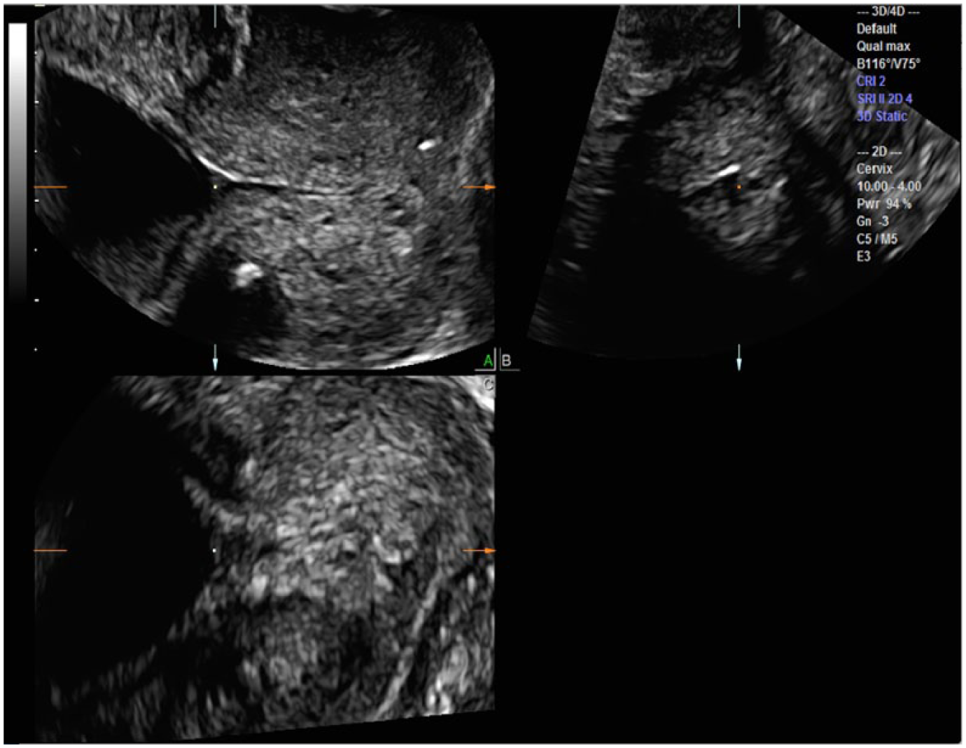
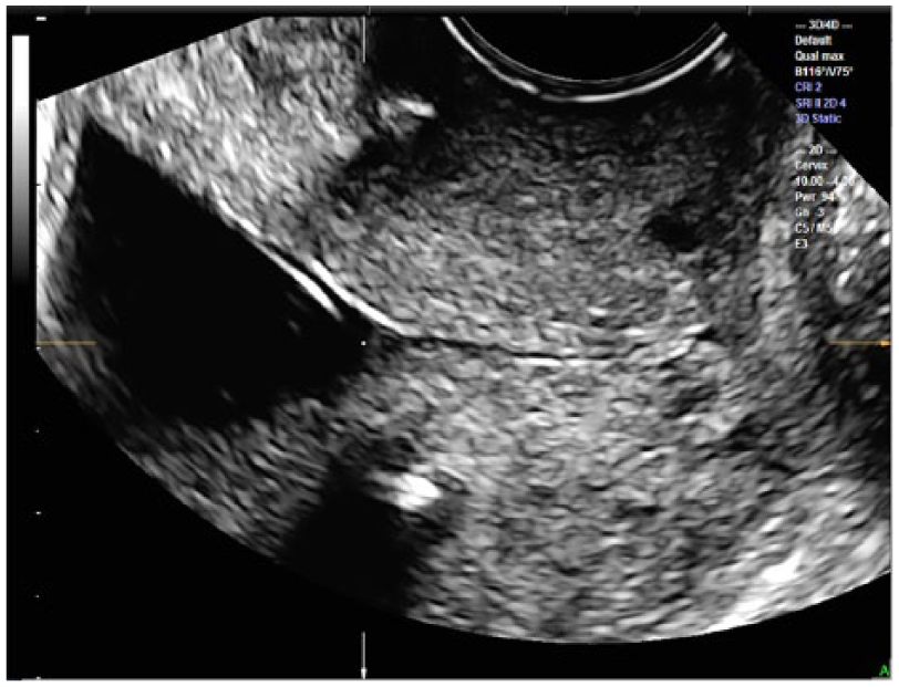
Manipulation of the CRP once again becomes integral to obtain an accurate measurement of cervical length within a 3D volume of the funneled cervix. Without movement of the CRP, the calipers will not be located at the correct AOI (Figure 3). In the presence of funneling, the CRP should first be moved to the edge of the funnel at the superior aspect of the internal os (proximal interface) on the midline sagittal A plane. Subtle X, Y, and Z axis manipulations can then be made on the transverse B plane and the coronal C planes to allow optimal visualization of the funnel on all three orthogonal planes (Figure 4). The most distal portion of the funnel, the point at which the cervical tissue is apposed, can now be clearly seen on the A and C planes, and the functional cervical length can now be accurately measured on the sagittal plane (Figure 5). This stepwise manipulation of the CRP in three dimensions prior to the final cervical length measurement in the sagittal plane ensures a consistent, accurate CL measurement.
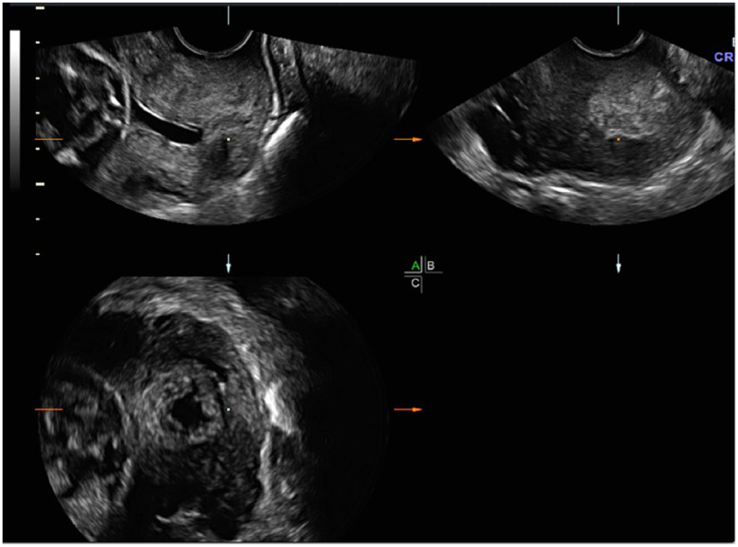
Initial three-dimensional sweep through a funneled cervical canal demonstrates the center reference point (CRP; square dot) at the center of all three orthogonal planes but not at the area of interest (AOI).
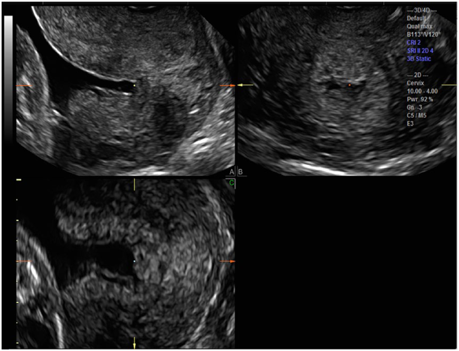
The center reference point (CRP; square dot) is moved to the internal os of the A plane for cervical length (CL) measurement. By rotating the A plane on the X, Y, and Z axes, the truly funneled internal opening is now confirmed.
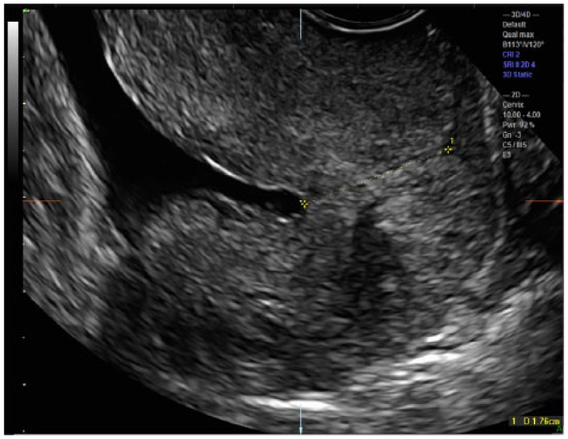
The A plane cervical length (CL) measurement (1.76 cm) can now be correctly obtained.
Cervical Cerclage
Visualization of the cerclage placement on a 3D volume set demonstrates its proximal to distal position and the adequacy of its closure at the jeopardized cervical opening. Following the initial sweep, the CRP is moved to the center between the two cerclage hyperechoic foci (Figure 6). Note that the C plane demonstrates that this point is not at the most proximal (anterosuperior) point of the internal os. By moving the CRP superiorly to the internal os on the C plane, the most proximal portion of the internal os can be confidently identified (Figure 7). Now, with the CRP located at the true internal os, X, Y, and Z axis manipulations will further refine the internal and external os visualization (Figure 8). Current 2D imaging may not have confidently identified the internal os location, and thus, the 2D cervical length may have yielded an inaccurate, shorter measurement.
By placing the center reference point (CRP; square dot) in the middle of the two foci of the cerclage on the A plane, the cerclage is also seen on the axial plane surrounding the proximal closed cervix. Note that the C plane demonstrates that this point is not at the most proximal (anterosuperior) point of the internal os.
The center reference point (CRP; square dot) is adjusted at the internal os on the C plane; however, the internal os on the A plane may be perceived as too cephalad.
X, Y, and Z axis refinements allow optimal visualization of the true internal and external os locations on the A plane.
A novel manipulation of the 3D volume set has been added to our protocol to improve visualization of the cerclage in relation to the cervix and to confirm a closed cervix. From the acquired midline sagittal volume set, the A plane is rotated on the Z axis to allow an anterior approach to the internal cervical os. The CRP is then moved to the point between the two cerclage hyperechoic foci on the A plane, which allows the cerclage to be viewed in its entirety on the C plane (Figure 9). Tomographic ultrasonographic imaging (TUI) cuts may be obtained, allowing multiple levels of the cervix to be assessed from anterior to posterior, though the initial cut can be changed to any of the original orthogonal planes (Figure 10). Further information can be garnered with a rendered view by altering the line of reference (LOR) in the volume set. In Figure 11, the green LOR is lowered toward the cervix in order to simultaneously demonstrate, in multiple planes, the closed cervix, the relationship of the cerclage to the cervix, and even visualization of the cerclaged knot.
Rotation of the A plane around the Z axis and placement of the center reference point (CRP; square dot) at the internal os on all three planes demonstrates the amniotic fluid at the top of the A plane image. The CRP is moved between the two hyperechoic cerclage loci, allowing the cerclage to be visualized in the C plane around a centrally located cervix.
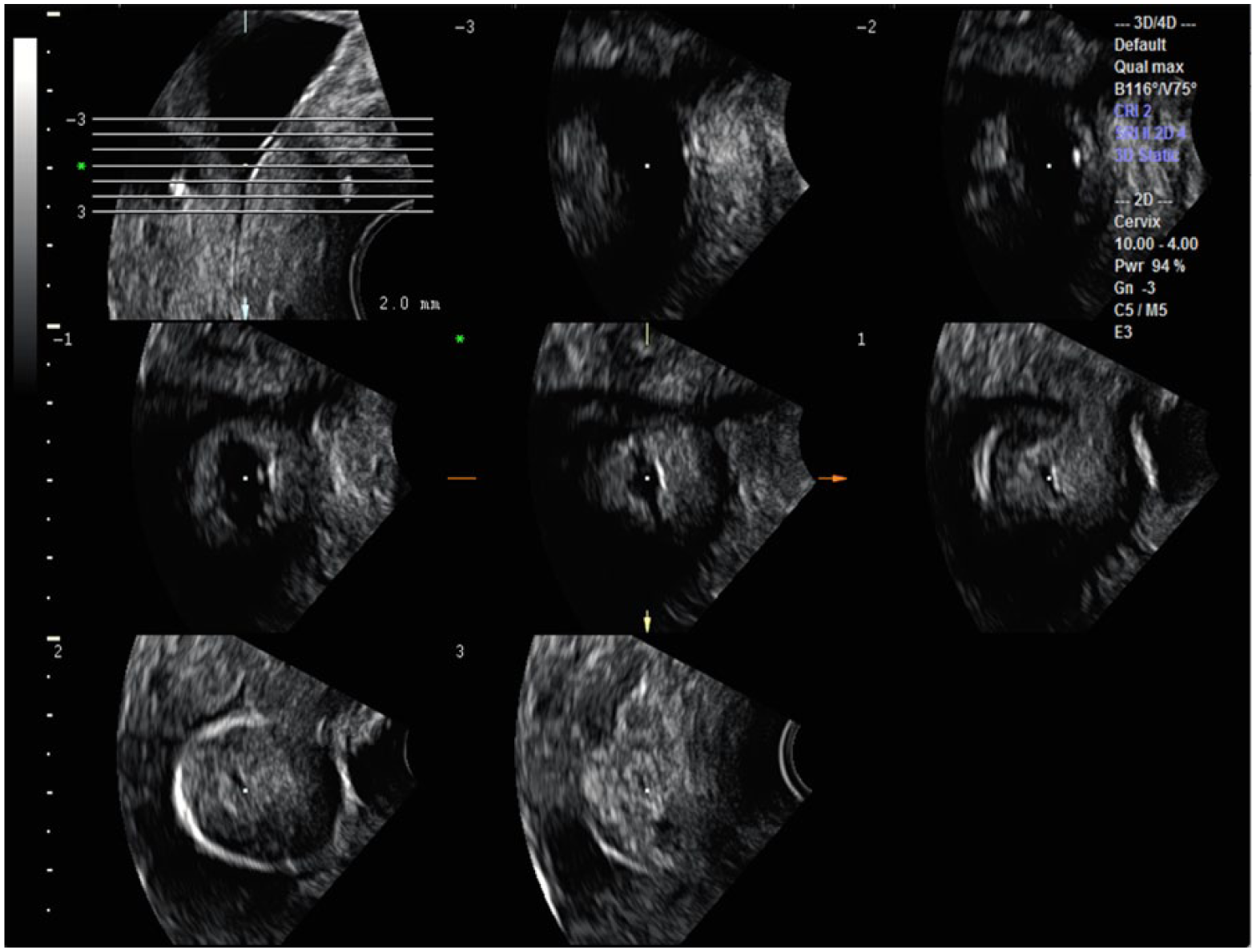
Tomographic ultrasonographic image (TUI) axial slices through the rotated A plane can demonstrate anterior to posterior cuts toward and past the cerclage, demonstrating the closed cervix.
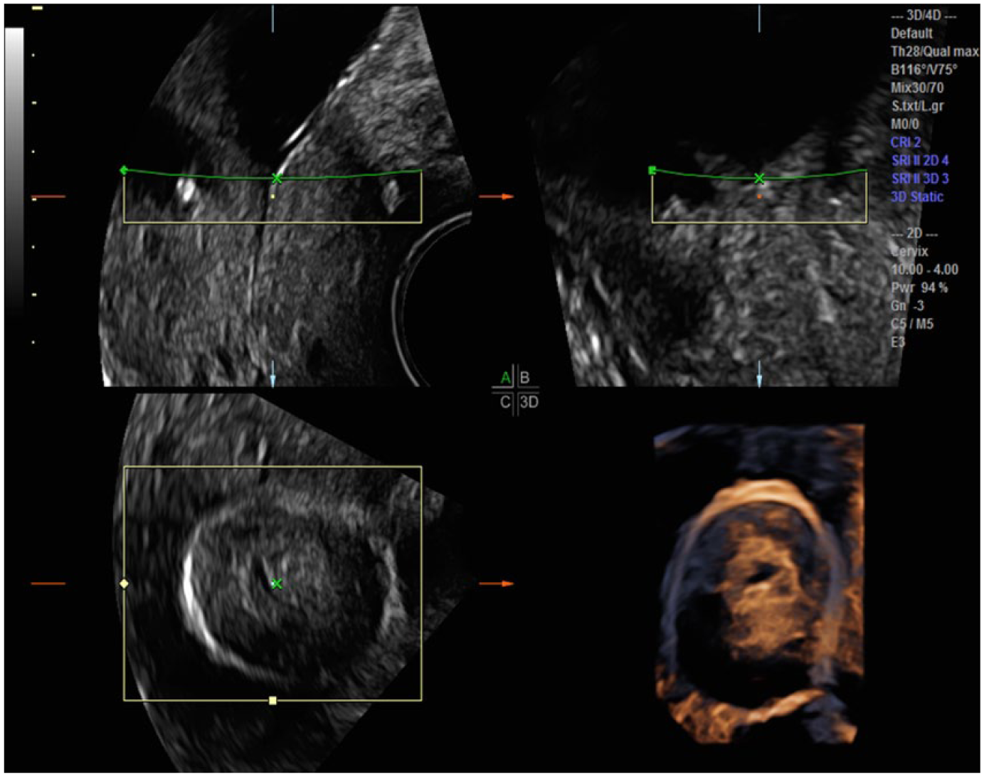
By placing the line of reference (green line) over the cerclage, it can be seen appropriately surrounding the cervix in the C plane as well as in the three-dimensional rendered image.
Visualization in Arbitrary Planes
An additional tool that can be utilized to improve 3D volume assessment is the use of commercially available software such as OMNI View (GE Healthcare) or other similar programs. This allows for visualization of any desired specific plane to be made through a volume set. A line, curve, or trace function is utilized to isolate any structure from a volume set and display it in a new single image plane (Figure 12). In particular, curved structures can be stretched out to improve visualization of actual morphology and can also be measured rather than subjectively assessed. Without this manipulation, a 2D curved structure may appear distorted or be difficult to measure.
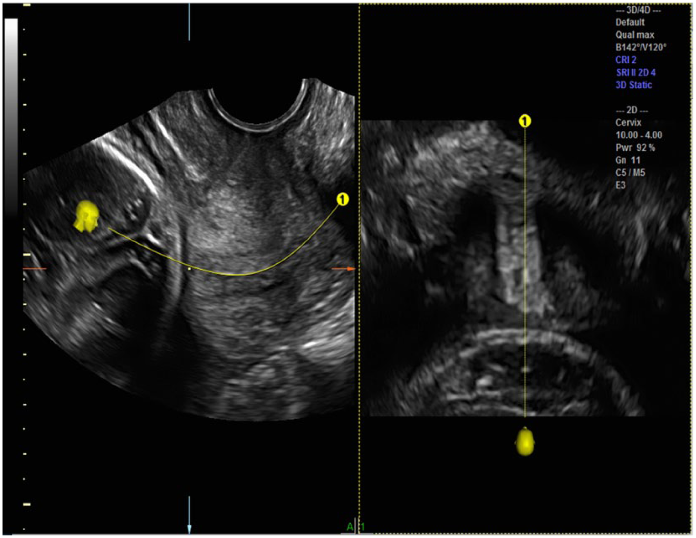
Software reconstruction programs such as OMNI View (GE Healthcare, Zipf, Austria) additionally allow visualization along any arbitrary plane within the volume set. By starting the OMNI cut anterior to the internal os (the fetal head) and extending the cut beyond the external os on the A plane, OMNI can lay out the anatomy of the cervix and further describe surrounding structures (fetal head, integrity of the cervical canal, and beyond the external os).
The OMNI View chosen plane through the cervix can be started at the specific area of the volume, such as the internal os or the external os. Alternatively, a trace can extend beyond the AOI on both ends (in this case, the fetal head, amniotic fluid, and beyond the external os) to demonstrate anatomy relative to the specific stretched out structure (in this case, the cervix) (Figure 12).
Discussion
As programs for the prevention of preterm birth have been instituted at the recommendation of the American College of Obstetricians and Gynecologists, 2D imaging of the cervix has become widely accepted as a screening tool for identifying patients at risk for preterm birth. 7 The Cervical Length Education and Review (CLEAR) program has provided national standards for 2D measurement of cervical length. This includes cervical measurement using an endovaginal transducer, demonstrating a midline sagittal image of the cervix that occupies 75% of the image screen (Figure 13). Both the anterior and posterior cervical component diameters should be equal, and both the internal and external os should be visualized. The cervical canal should be visible throughout, and the measurement caliper placement should be correct, starting at the two apposing sides of the closed cervical interfaces. Cervical mobility should be considered, and the examination should last at least three minutes to allow transient dynamic changes of the cervix.6,8
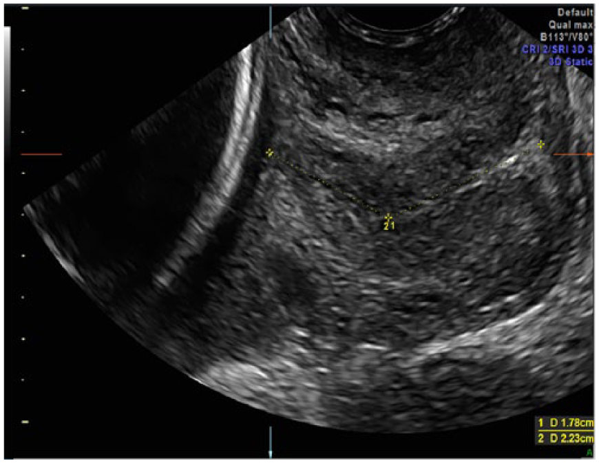
Conventional two-dimensional cervical length (CL) measurement is measured in the A plane starting from the internal os to the external os.
Reference values for CL comparison between 2D and 3D measurements have been published. 9 There was excellent agreement between 2D and 3D measurements (interclass correlation coefficient values, 0.80-0.98), but CL measurements taken with 3D were greater than measurements with 2D (mean difference 0.04 ± 0.36 cm). 9 Cervical length measurement by 3D ultrasonography is thought to yield more accurate measurements than 2D, and CL measurements with 3D are greater than with 2D ultrasonography.9–11 Three-dimensional ultrasonographic characterization of cervical measurement in the presence of funneling has been described previously. 12 These prior publications, however, did not provide a detailed description as to how the 3D volume was manipulated in order to optimally evaluate cervical funneling. Although the presence of funneling has been previously shown to have little prognostic significance with regard to preterm delivery, the presence of funneling does further complicate accurate measurement of cervical length. 13
Few authors have described a step-by-step approach to using 3D ultrasonographic imaging to garner information regarding cerclaged cervical assessment. Bega et al. 10 describe 3D imaging in order to visualize the cerclage in its entirety and ascertain symmetry of cerclage placement. One case report depicts 3D render imaging from a transperineal approach. 13 Others have constructed models from 3D imaging to gain additional anatomical information of cerclage placement. They emphasize that information regarding cervical morphology is lost with performance of 2D cervical length measurement only. 14 Three-dimensional volume imaging has created a plausible methodology to verify and enhance these 2D measurements. To our knowledge, discussion of step-by-step 3D volume manipulation with utilization of the CRP has not been reported related to CL assessment of the normal, shortened, funneled, and cerclaged cervix. As more imaging centers become acquainted with software reconstruction programs such as OMNI View, the individually created planes through the cervix and surrounding relational anatomy will be more reliably assessed and reproduced.
Summary
The 3D reconstruction and manipulation of the cervix, enhanced by the utilization and manipulation of the CRP within the cervix, endocervix, and internal os, has enhanced our knowledge of this complex anatomy. It appears to be the key to obtaining more precise imaging parameters used for prognosis. This methodology provides the clinicians, sonologists, and sonographers with an important tool to assess the positioning and dilatation of the cervix on any 3D volume set. Three-dimensional reconstruction of the cervix, especially precise utilization of the CRP and available image reconstruction software, augments current 2D morphologic information of the lower genital tract.
Footnotes
Declaration of Conflicting Interests
The authors declared no potential conflicts of interest with respect to the research, authorship, and/or publication of this article.
Funding
The authors received no financial support for the research, authorship, and/or publication of this article.