
Abstract
Different viscous materials were chosen to simulate the behavior of degraded materials in the thermoforming process and to demonstrate the potential of using multilayer sheets for thermoforming non thermoformable materials without losing final part performance. The mechanical properties of thermoformed multilayer sheets with 3, 22, and 50 melt flow index (MFI) polypropylenes (PP) were investigated. Therefore, a thermoformable material (MFI-3) and difficult/non thermoformable (MFI-22 and MFI-50) material was combined in the bilayer sheet. The extruded bilayer sheets had equal layer thicknesses (A/B 50%/50%) and unequal layer thicknesses (A/B 70%/30%), whereby B is always the material difficult to thermoform. As the non thermoformable material can lead to inhomogenity in the wall thickness and therefore can cause different part performance, the investigation focused on how the non thermoformable material influenced the mechanical performance of the final part. This labortory scale thermoformability investigation of the extruded PP sheets with different viscosities showed that the low viscous layer position has only a marginal influence on the general mechanical properties of the thermoformed parts. The mechanical properties can be predicted more precisely by the mechanical properties of the thermoformable material used than by the rule of mixtures. Whereas the Young’s modulus and yield stress change only negligibly, the elongation at break after thermoforming significantly increases with the stable component.
Introduction and state of the art
The thermoforming process is mainly used for thin-walled, and in some cases also large-area components. 1 The whole process can be divided into five steps. 2 More precisley, clamping the sheet in the thermoforming machine, heating, forming, cooling and demolding. 2 The forming is mostly done by vacuum or pressure. 3 The stretching process is mainly known from fiber spinning, blow molding or thermoforming.4,5 Also mainly due to the product spectrum that thermoforming serves, standard polymers as for example semicrystalline polymers like polyethylene and PP or amorphous polymers like acrylonitrile-butadiene-styrene (ABS) are often being used.2,3 In contrast to amorphous polymers, thermoforming semi-crystalline polymers presents a major challenge, as semicrystalline polymers exhibit low melt stiffness. 6 The main problem with low melt stiffness is their high sagging tendency during the heating phase. In order to overcome sagging, materials with broad molecular weight distribution should be processed as viscosity increases due to the entangled melts. 7 Rheological properties as the ratio between storage modulus and loss modulus can give indications about suitability for thermoforming as their ratio (tanδ) should be close to 1. 8 Grades with a low melt flow index should be chosen especially for processing PP as longer molecular chains hinder sagging during heating. 9 To increase melt stiffness it is also possible to use chain extenders like peroxides. An increased long-chain branching is linked with improved thermoformability. 10 It can not be ignored that the peroxide content has an influence on crosslinking. 11 Strain hardening during extensional stress can also be caused by the long chain branching.12,13
As it can be seen, the demands on rheological parameters are high and in particular makes thermoforming of use-induced or processing-induced degraded polymers difficult. 14 As PP degrades during multiple processing viscosity decreases. Degradation is dealt with in many publications, as it is a well-known problem in polymer processing. A decrease in viscosity for degraded PP can be found because of decreasing and narrowing molecular weight. 15 Chain scission is the dominant PP degradation mechanism which leads to a lower viscosity. 16 The relative chain scission depends on the molecular weight. 17 This molecular weight decrease can be identified by the cross-over point.18,19 The cross-over point shifts upward for a narrow molecular weight distribution, while a wider molecular weight distribution causes a downward shift. However, the cross-over point is located left for long or branched polymer chains and right for shorter or less branched ones. 20 Not only the rheological but also the mechanical properties are greatly influenced by degradation. The degradation has a particular effect on the mechanical properties such as elongation at break. Due to the increasing chain scission, the elongation at break decreases.14,21
Since the material used in thermoforming significantly influences the process due to its deformation behavior, there are many studies dealing with the material behavior under strain.22,23,24 In general, polyolefins with a sufficiently high molecular weight are very ductile at room temperature. 25 In the case of semi-crystalline polymers, introducing strain onto a specimen initially leads to viscoelastic stretching of the molecular chains. When yield point is reached, the molecular chains begin to slip, flow begins. 26 For analyzing deformation behavior, mainly uniaxial force-displacement curves are used. Here, Young’s modulus, yield stress and strain limit can be named as essential material parameters. 23
Although the mechanical properties of thermoformed parts play a significant role in determining part performance, there are few approaches that correlate part behavior, with processing and material behavior. Liebing 27 investigated for example the mechanical properties of amorphous polyethylene terephthalate (PET) and found a correlation between forming temperature, forming rate and Young’s modulus. While at higher draw ratios a higher forming temperature leads to a lower Young’s modulus, since this increases the degree of crystallinity and decreases the orientation, at low draw ratios the Young’s modulus is almost independent of the forming temperature. 27 There are no studies dealing with the influence of low viscous not thermoformable materials in multilayer sheets on the mechanical properties of thermoformed parts.
Multilayer sheets are used in thermoforming for optical or functional reasons. 28 In food packaging, a reduction in the oxygen barrier and a brightness decrease resulting from the stretching process. 29 The ethylene vinyl alcohol (EVOH) used in food packaging has special requirements for the thermoforming process due to necking. 30 Multilayer sheets are also used with one layer containing recycle material. The investigation of Badeka et al. 31 on migration, barrier and mechanical properties of 40–50 weight-% low density PE in multilayer sheets showed no influence of recycled material on these properties. 31 The question arises whether, using a multilayer sheet, is it possible to process low-viscosity materials, as are known from the field of recycling, in thermoforming and at the same time not to suffer any loss in mechanical part properties.
A multilayer sheet creates a stabilizing layer that prevents the sheet from sagging during thermoforming and ensuring that the mechanical part properties are not affected by the forming process. Therefore, different PPs (MFI-3, MFI-22, MFI-50) are used for extrusion and thermoforming in this investigation. This investigation is an extension of Wittmann and Drummer 32 and, in contrast to the previous study, focuses on the mechanical properties of multilayer sheets with low viscous materials. The wall thickness homogeneity of the whole part as well as the mechanical properties of the two-layered sheets with different layer ratios were examined versus the layer position during the forming process. The structural properties of the sheets and parts were also taken into account.
Materials and methods
Used materials
Materials and used abbreviations.
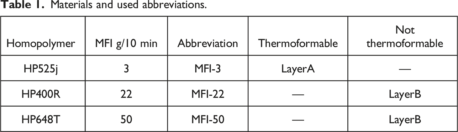
The material HP525j (MFI-3) was always used as a thermoformable material (Layer A) in the multilayer sheet. It was always combined with a non thermoformable or hardly thermoformable material HP400 R (MFI-22) or HP648 T (MFI-50) (Layer B). The reason why these materials were chosen is explained in detail in Wittmann and Drummer. 32 The individual layers were separated by coloring one layer. Therefore, the two materials MFI-22 and MFI-50 were colored with yellow masterbatch pigment REMAFIN-PE-GELB TIRN from Avient Corporation (formerly Clariant Masterbatch), Performance Masterbatches Germany GmbH, Lahnstein, Germany. The yellow masterbatch pigment of 1 weight-% was added by dry blending to the granulate.
Experimental set-up
Sheet extrusion
Melt pump setting for extrusion of different layer configurations.
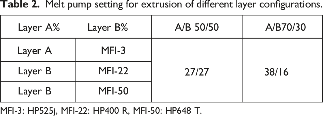
MFI-3: HP525j, MFI-22: HP400 R, MFI-50: HP648 T.
Thermoforming
Thermoforming experiments were conducted on a single-station vacuum forming machine Berg Mini M3 (Berg Engineering GmbH, Berlin, Germany). An aluminum cuboid truncated pyramid male thermoforming tool was used for testing. Figure 1 shows the tool and the dimensions as well as the used sheet orientation during thermoforming.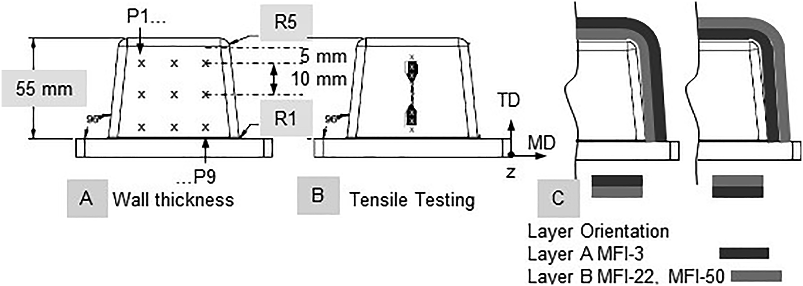
Figure 1 also depicts the wall thickness measurement locations on the thermoformed part as well as the tensile bar location.
The wall thickness change in the flank was calculated according to equation (1)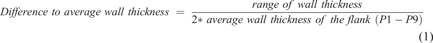
The tool has an average surface roughness Rz of 14 μm that was measured with the roughness tester Surtronic 10 (Taylor-Hobson, AMETEK, Inc, Weiterstadt, Germany). The tool speed was approximately 140 mm/s and the tool temperature was 80°C for all investigations which is a standard tool temperature for processing PP. 1 The sheet was heated with upper and lower quartz radiant heaters (type SQE 80x60, 150 W; Friedr. Freek GmbH, Menden, Germany) to its 180°C forming temperature. The heating process was controlled by a pyrometer (type 22MID10LTCB3; Schlender Messtechnik e.K, Berlin, Germany). The cooling time was 20 s. In order to evaluate the wall thickness distribution and the mechanical properties of the thermoformed part, a 2.0 areal draw ratio was used.
As the orientation of the sheet during thermoforming is varied, the following nomenclature is used. The material facing away from the forming tool is placed first (top layer) and the material close to the forming tool (forming tool layer) is second. For example, MFI-3/MFI-22 means that HP525j is away from the tool and HP400 R contacts the tool.
Characterization
Analysis of the thermal properties
To determine how the yellow masterbatch pigment influences the thermal behavior of the polymers, differential scanning calorimetry (DSC) measurements were performed using a Discovery-2500 TA instrument (Waters Corporation, Milford, USA) according to DIN EN ISO 11,357-1. The sample weight taken in the present study was approximately 2 - 5 mg. The sample is heated together with a reference specimen from 20°C to 200°C at a heating rate of 10 K/min under a nitrogen atmosphere. This is followed by an isothermal holding time of 30 s. The subsequent cooling to 20°C was carried out at a cooling rate of 10 K/min. The heat flow between the sample and the reference is measured as a function of temperature. The second heating is identical to the first.
Analysis of the rheological behavior
For rheological studies, a Discovery HR-2 (TA-Instruments, Inc., Waters Corporation, Hüllhorst, Germany) plate-plate rheometer was used to determine different material characteristics. Therefore, a pellet is positioned between two axially symmetrical rotation plates. While one plate is fixed, the opposite plate can move in a rotating or oscillating manner,
33
so that a drag flow is induced in the polymer.
34
The stress response corresponds to the viscoelastic properties of the polymer melt. In the following investigation, the measurements are carried out in the molten state in a temperature range of 170°C to 192°C. The measurements were performed in steps of 2°C. The measurements were made from 0.1 rad/s to 100 rad/s. The cross-over time, which determines the change of the viscous and elastic behavior
29
, was calculated according to equation (2)
Optical analysis of the extruded sheets and thermoformed parts
The layer thickness distribution over the cross section was analyzed with a linearly polarized light microscopy (0°). For thickness distribution analysis, 10 μm cross sections were made perpendicular to the extrusion direction. The cross section was first embedded in epoxy, then ground and polished. Afterwards, the cross sections were analyzed with a Axio Imager.M2 (Carl Zeiss AG, Oberkochen, Germany) microscope at ×100 magnification. The images were made using the objective EC Plan-Neofluar ×10/0.25. The thermoformed part specimens were located at P5 as this is in the middle of the tensile bar. The sampling direction was oriented in the stretch and perpendicular to the extrusion direction
Structural analysis of extruded sheets and thermoformed parts
The degree of crystallization is determined by infrared spectroscopy (type Nicolet 6700 FT-IR, Thermo Fisher Scientific, Cooperation Waltham, Massachusetts, United States) on 10 μm thin sections over the entire cross section of the sheet respective thermoformed part. The thin cuts are taken at the same positions as described in 2.3.3. The measurements are performed in 10 μm steps. To determine the degree of crystallization, the 840 cm−1 to 973 cm−1 absorption band ratio is calculated. 35 The 973 cm−1 band corresponds to the amorphous phase, the 840 cm−1 band is the crystalline phase.
Measurment of the wall thickness of the thermoformed parts
The wall thickness distribution was evaluated before and after thermoforming at the whole part flank with a Dualscope FMP100 thickness gauge measurement system (HELMUT FISCHER GMBH, Institut für Elektronik und Messtechnik, Sindelfingen, Germany). Figure 1 left shows the wall thickness position of the entire thermoformed part and the tensile bar thickness was determined in the middle of the part flank. Here, the distance between the measuring points was reduced to provide a better indication of the specimen wall thickness. Figure 1 middle shows the measurement points of the tensile bar specimen.
Mechanical behaviour of extruded sheets and thermoformed parts
In order to evaluate the part performance, tensile tests according to DIN EN ISO 527-1 are performed. Due to the geometric dimensions of the thermoformed parts used in this work, from which the tensile bars are prepared, as well as their low wall thickness, a tensile bar geometry according to DIN 53,504 (form S2) is selected. According to DIN EN ISO 527-1, it is recommended to determine the Young’s modulus as a secant between the strain values of 0.05% and 0.25%. If it is necessary due to the shape of the curve, other evaluation limits are also permissible. In accordance with the DIN EN ISO 527-1, a test speed of 10 mm/min must be applied as the clamping length of the specimens is only 20 mm. In each case 5 replicate tests were carried out.
Results and discussion
Results of the material characterization
How the yellow pigment influences the melting and recrystallization behavior is investigated by DSC. Figure 2 shows the first melting and cooling behavior of the monolayer sheet at a heating rate and cooling rate of 10°C/min.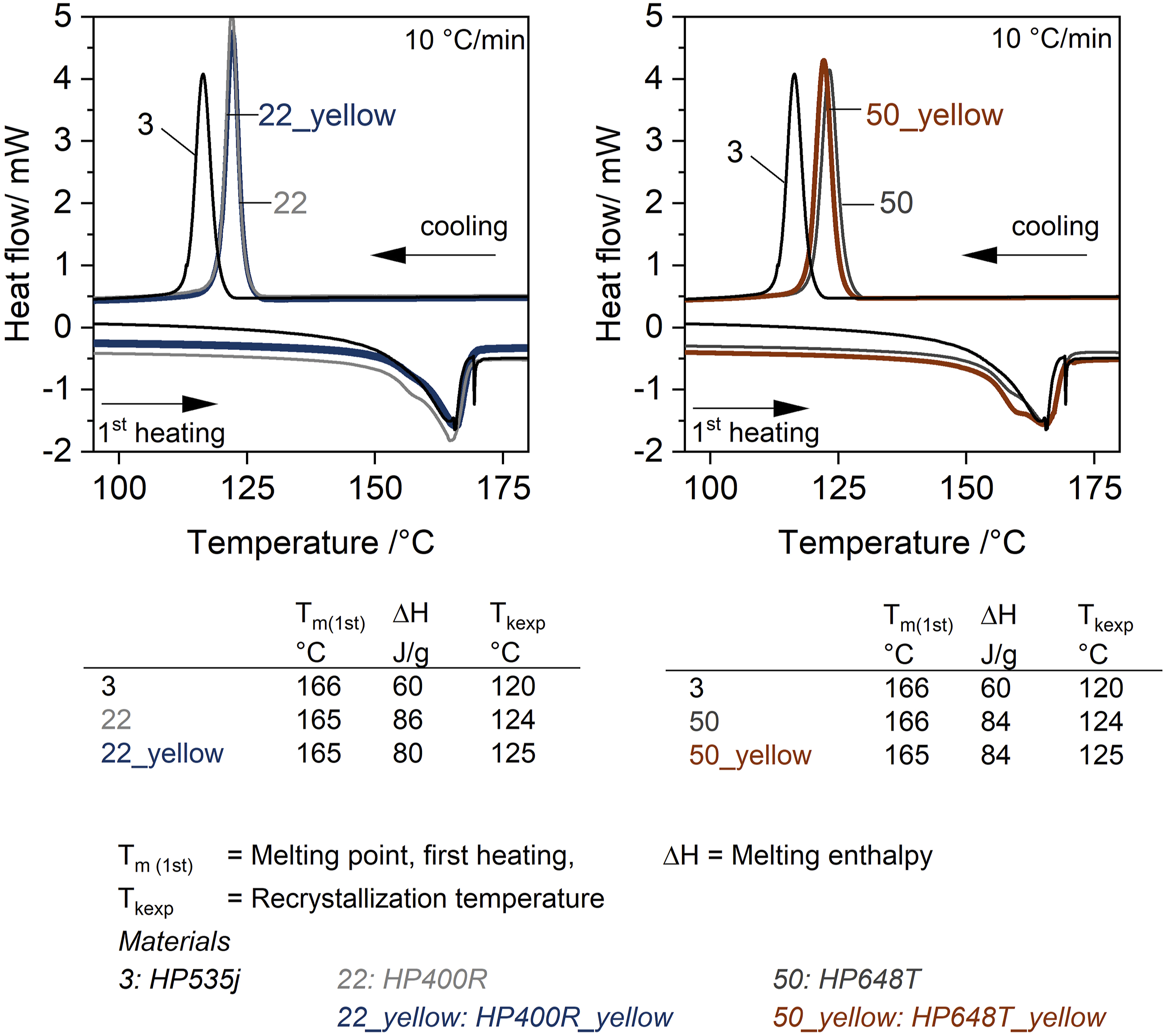
Figure 2 gives the melting peak and recrystallization temperatures for both unpigmented and pigmented sheets. Both the melting peak and recrystallization temperatures are at similar values for the materials used. Contrary to the behavior known from the literature, 36 the pigment used does not accelerate crystallization and recrystallization does not start at elevated temperatures. For pigmented material 50r the recrystallization temperature even appears to be at lower temperature.
Figure 3 shows the comples viscosity that has a significant influence on processability in thermoforming. Complex viscosity versus Angular frequency for the materials used.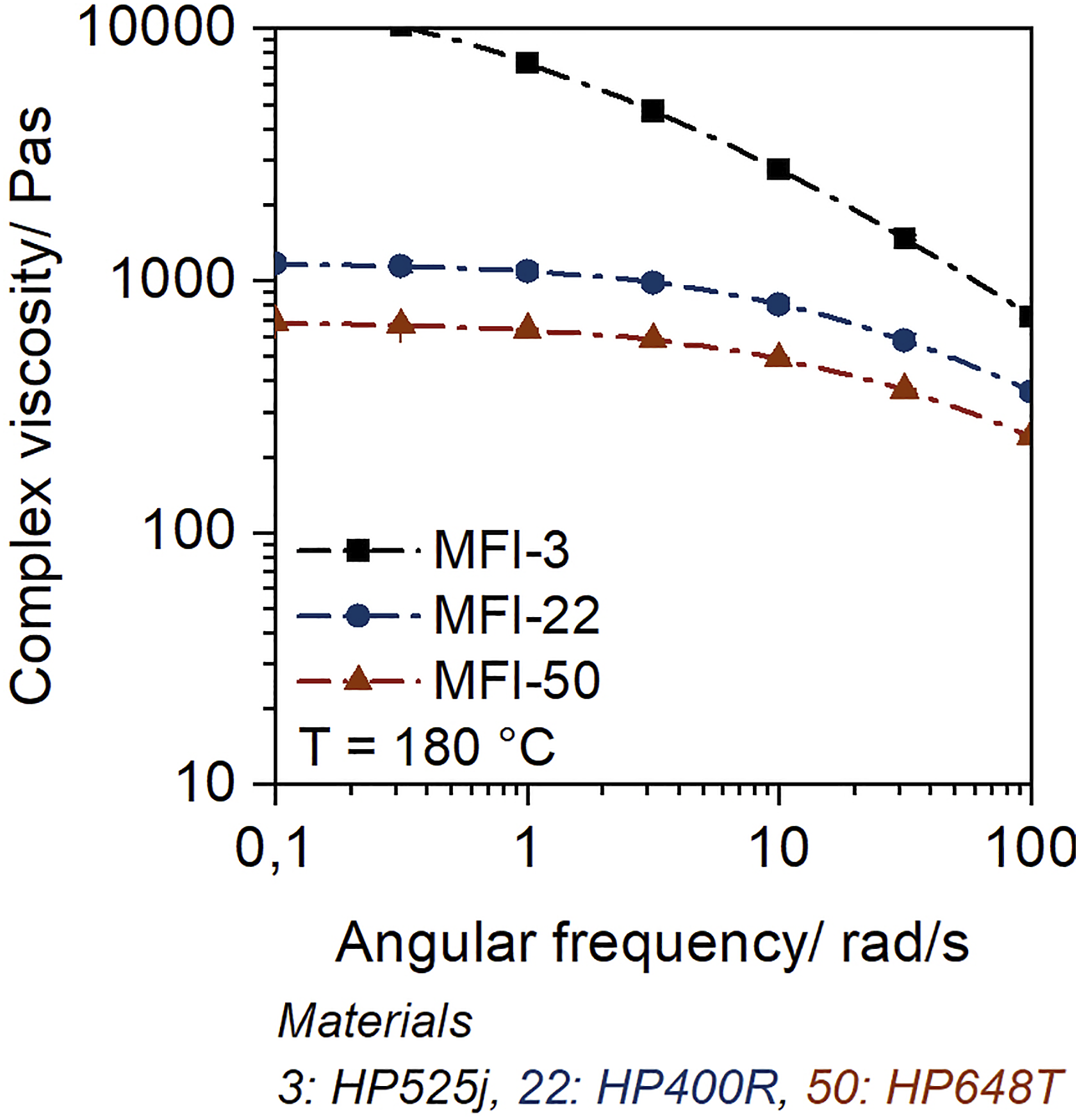
While the complex viscosity of MFI-22 and MFI-50 is in the linear viscoelastic range (0.1 −1 rad/s) just around 1000 Pas, the viscosity of MFI-3 is more than 10 times higher. The complex viscosity of the materials clearly indicates that the MFI-3 material is well suited for thermoforming and the MFI-22 and MFI-50 materials are less useful for this processing method due to their low zero shear viscosity.37,38
Results of the rheological analysis
Figure 4 shows the rheological analysis, the temperature and frequency-dependent storage modulus (Figure 4 left), the cross-over frequency (Figure 4 right) and the calculated cross-over time (Figure 5). Calculated cross-over time versus Temperature for the granulate MFI-3, MFI-22 and MFI-50 between 170°C to 190°C.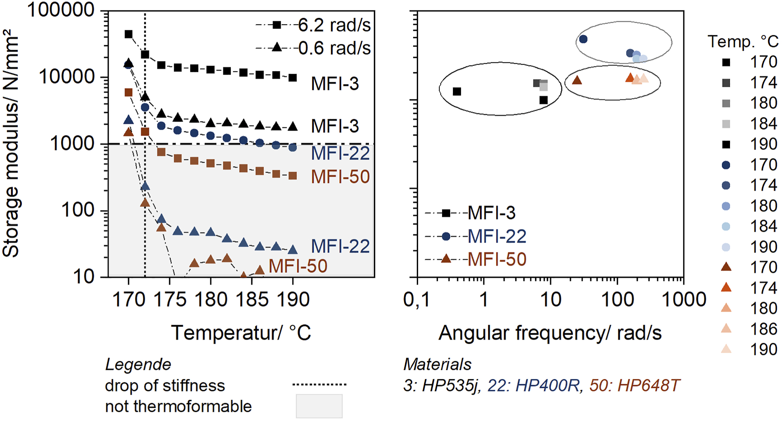

The storage modulus (Figure 4 left) is evaluated both at a low frequency (0.6 rad/s) and at the standard measurement frequency (6.2 rad/s). For all homopolymers, the drop in stiffness after 170°C is evident. After that, the storage modulus curve converges towards a plateau. While the storage modulus for MFI-3 remains above 1000 N/mm2 over a wide temperature range for a low frequency used for evaluating material parameters for thermoforming, the curves for MFI-22 and MFI-50 even run well above 100 N/mm2. The small storage modulus indicates the arising thermoforming problems37,38 for the materials MFI-22 and MFI-50.
Figure 4 right shows the temperature-dependent cross-over point. One sees that the cross-over points are in a very narrow range for each material at temperatures greater than 174°C, which can be explained by the molecular chains have higher mobility evidenced by the decreased storage modulus. For the material MFI-3, with the higher average molar mass, the cross-over point is at lower frequencies because the molecular chains are less mobile and cannot follow the higher frequencies. 34
Figure 5 shows the inverse of the cross-over time frequency versus temperature. The time can be calculated for the change of viscous and elastic behavior. 39
The time required for the elastic into viscous behavior change is, for example, 20 times longer for MFI-3 at 180°C than for MFI-22, even 30 times for MFI-50. This means that the time to an undefined beginning of flow is significantly higher for the thermoformable material than for the non-thermoformable material.
Optical and structural analysis of the thermoformed parts
Figure 6 shows how the inner structure of the parts before and after thermoforming using thin cuts. Optical analysis of the sheets and the thermoformed parts.
The optical analysis of the sheets shows that there is uniform stretching of both layers at the position considered regardless of the material combination. The original layer configurations are not affected by thermoforming. Due to the very fine spherulitic structure, caused by the pigment, before forming, no difference can be seen after forming. Less attention should be paid to the overall thickness of the thin cuts, as this depends on the sampling position and may contain minor variations. Figure 7 shows that the degree of crystallinity indicates that the sheets already have a high degree of crystallinity before thermoforming.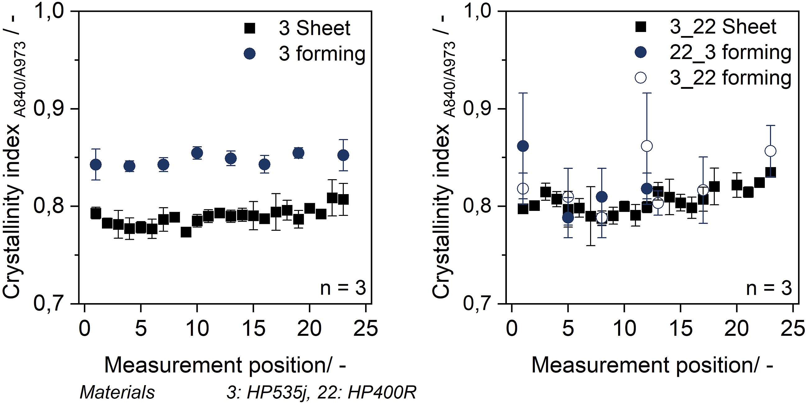
For monolayers, there is a slight increase in crystallinity. 40 For multilayer sheets, in accordance to the high standard deviations, no differences can be detected.
Wall thickness of the thermoformed parts
A wall thickness distribution was evaluated along the flank (see Figure 1 right) to ensure that homogeneous specimens could be prepared for the tensile testing. For all configurations, a homogeneous wall thickness at the preparation position and no extreme thinning could be determined. The measuring points P3 - P6 are not dependent on the position of the non thermoformable material. Overall, the deviations of minimum and maximum wall thickness in the multilayer sheets are between ±50–70 μm and slightly higher than in the monolayer MFI-3 (±25 μm). This deviation can be explained by the low viscosity material. For all configurations, the maximum mean wall thickness reduction was approximately 60%. This close examination of the wall thickness reduction showed that no weak points in the specimen could influence the mechanical behavior of the thermoformed part.
In order to evaluate to what extent the product quality is still valid as a function of the process-related wall thickness reduction, the average flank wall thickness of the whole part was calculated. The range (minimum and maximum wall thickness) was related to the average flank wall thickness (P1 – P9) in each case, according to equation (1). A change in wall thickness of ±30% is accepted.
1
Figure 8 depicts the wall thickness variability for the whole part flank.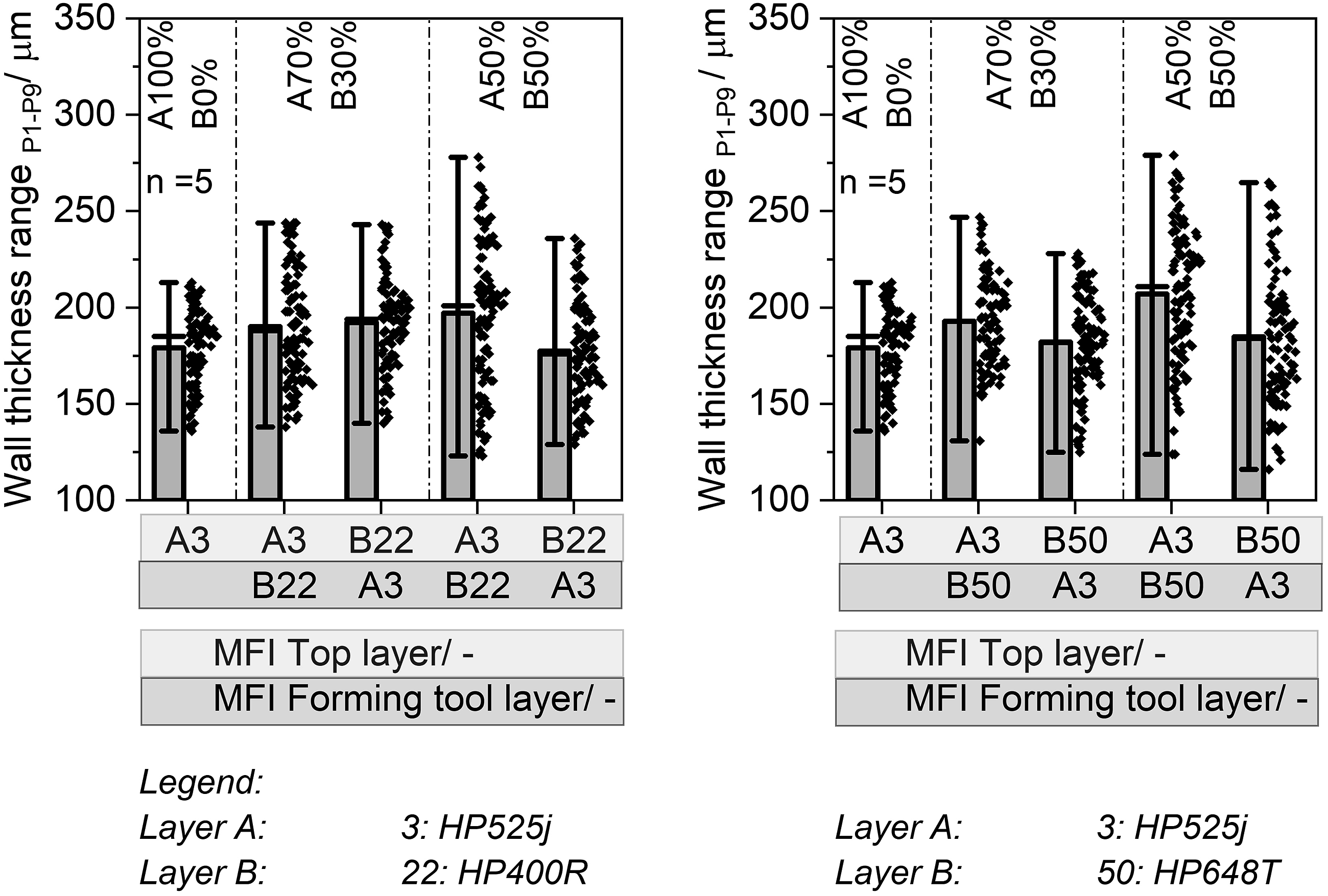
The Figure 8 left results show that for the thermoformable material MFI-3, the wall thickness change is within the tolerable range. A correlation between the layer ratio and the position of the stabilizing thermoformable material can be seen. In case where the stabilizing material is in contact with the tool, the deviation is still in the tolerable range. The material behavior of the unstable material seems to have only a minor influence here as for MFI-3/MFI-22 and MFI-3/MFI-50 (Figure 8 right) similar results are observed. An explanation for this can possibly be found when considering the cross-over time frequency and the change of viscous and elastic behavior. While the cross-over time for MFI-3 remains constant over a wide temperature range even after the stiffness drop, for MFI-22 and MFI-50 the cross-over time decreases continuously after the stiffness drop and the material starts to flow. This flow can be balanced by using the thermoformable stable sheet as layer at the forming tool. That no influence of the layer position could be found for the rotation-symmetrical parts used in Wittmann and Drummer 32 can be explained on the one hand by the geometrical reasons and on the other hand by the measurement position. While in Wittmann and Drummer 32 the maximum wall thickness reduction at the maximum stretched location in the part flank was analyzed, in the present study the complete part flank was considered. Furthermore, the rectangular contact surface induces a different elongation behavior than a rotationally symmetrical one, since heat is dissipated much faster when the tool contacts the sheet surface due to the larger contact surface.
Figure 9 shows that the wall thickness are within the tolerances (30%
1
) for the layer configuration containing 70% thermoformable material, regardless of the non-thermoformable material (MFI-22 or MFI-50) and the stabilizing layer position. Deviation to average flank thickness.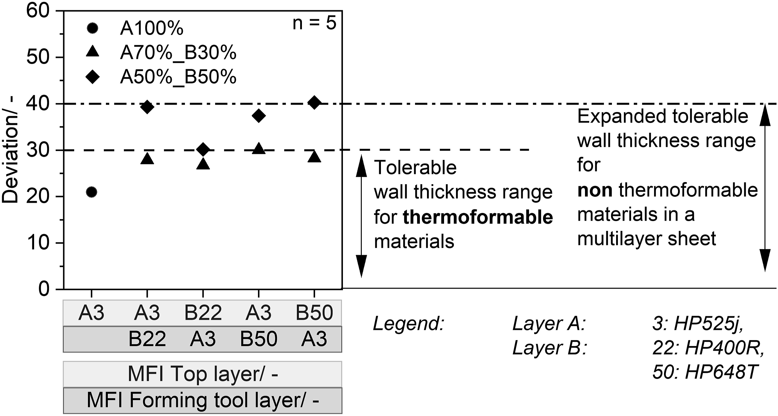
For the same layer ratio (A/B 50/50), the range only expands to 40. The rank evaluation shows that a stabilizing effect of the non-thermoformable material during forming is achieved by the thermoformable material. While the stabilizing effect as a function of the layer position is more pronounced for MFI-3/MFI-22, it is slightly reduced for MFI-3/MFI-50. However, the presence of the thermoformable material makes it possible both to process low viscous fractions and to obtain only slight reduction in wall thickness homogeneity. For the processing of previously unprocessable materials, the tolerance limit might have to be increased only to a small extent. This could be justified in view of the obtained mechanical properties discussed below.
Mechanical behavior of the extruded sheets and thermoformed part
Mechanical properties of extruded and thermoformed mono- and multilayer sheets.
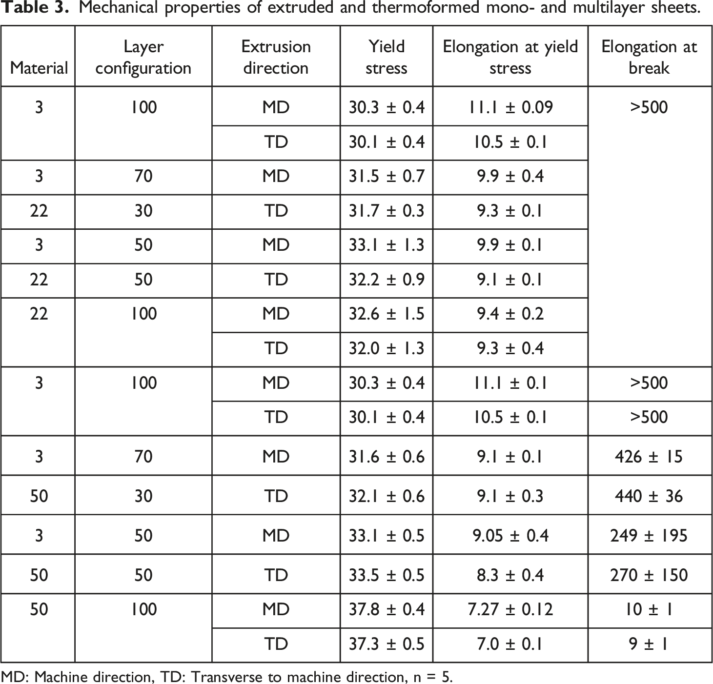
MD: Machine direction, TD: Transverse to machine direction, n = 5.
The results show that, due to the selected low haul-off speed of 1.2 mm/min. During extrusion, no preorientation and thus no change in the mechanical properties as a function of the extrusion direction occurred. These balanced mechanical properties both in (MD) and transverse to the extrusion direction (TD) are of great advantage for subsequent thermoforming, since no direction-dependent properties and thus no anisotropies are generated in the thermoformed part. Since the MFI-3 and MFI-22 monolayer mechanical properties are rather similar, the multilayer sheets exhibit similar mechanical properties, such as yield stress. The elongation at break for MFI-3 and MFI-22 is higher than 500% for all configurations. The fact that no elongation at break could be measured was due to the limited traverse distance with the test machine. The 500% elongation corresponds to the end of the traverse travel. It is noticeable that the MFI-50 material has a very low elongation at break (about 10%) in the monolayer. The low elongation at break of MFI-50 affects the elongation at break of the multilayer sheets, so that the elongation at break of the multilayer sheets only reaches about 250% for equal layer thicknesses. The yield stress behaves according to the individual components and follow the rule of mixtures.
Figure 10 shows the mechanical properties of the thermoformed parts. The Young’s modulus can indicate the relationship between microstructure and mechanical properties.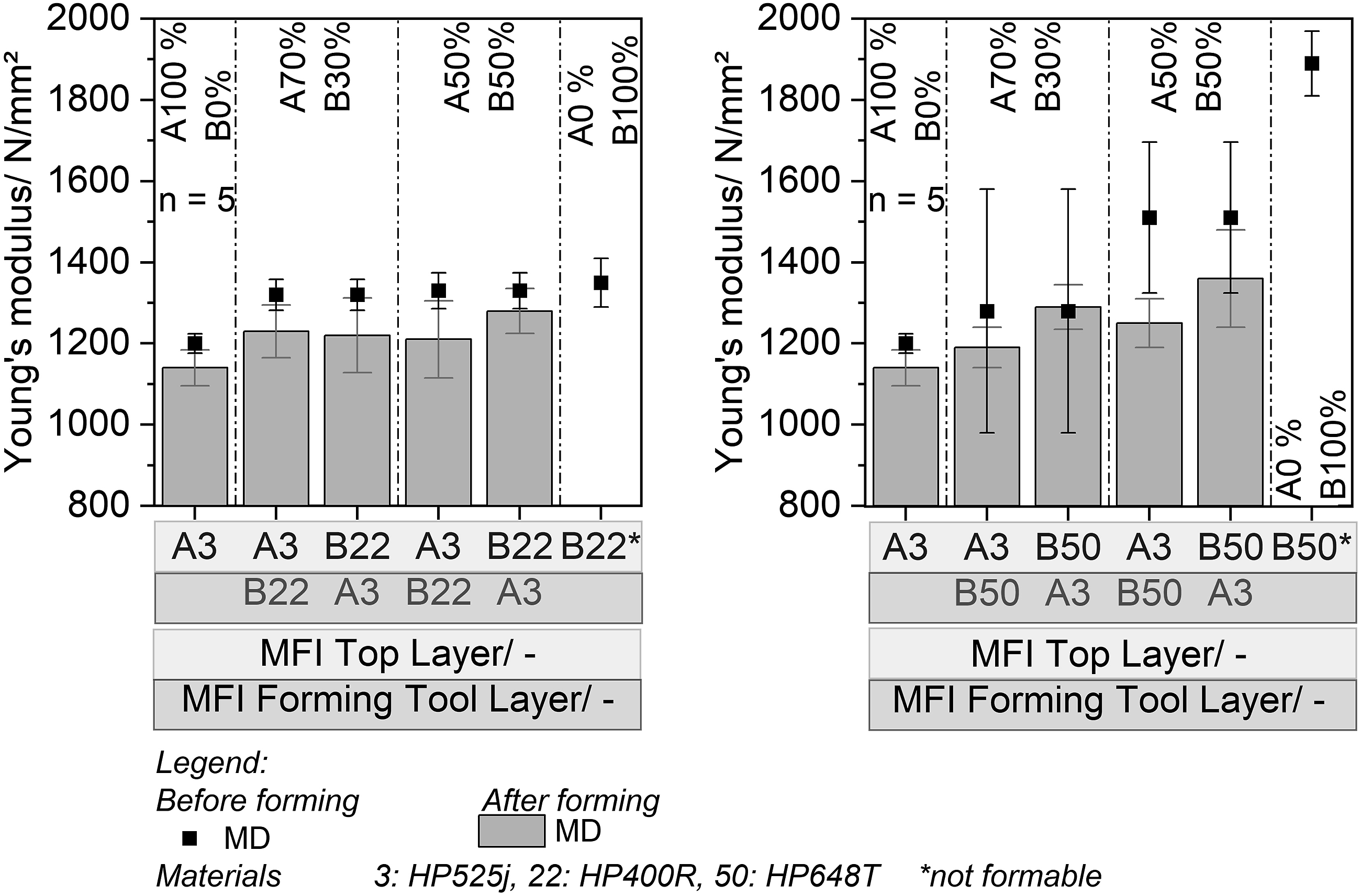
The results show that the mechanical properties such as the Young’s modulus of the parts are not affected by materials that are difficult to thermoform. The properties of the parts are tolerably at the same level as the extruded sheets. The small decrease in mechanical properties in both the monolayer (MFI-3) and the multilayer sheet (MFI-3/MFI-22 and MFI-3/MFI-50) can possibly be explained by the very thin specimens (<200 μm). Furthermore, the slight decrease of the Young’s Modulus can be caused by the chosen forming temperature that increases the degree of crystallinity, even if it is not significant as it could be seen in Figure 7, and decreases orientations. 27 Edge effects that could occur due to the punching out of the test specimens can be eliminated, since the elongation at break was over 500% for all configurations. The fact that there is no evident increase in Young’s modulus can possibly be explained by the 2.0 areal draw ratio and fast sheet cooling, which prevents crystalline structure growth.
Now, the stress-strain curve of the sheets will be considered and the tensile stress at selected strains will be evaluated. Figure 11 left shows an example of the stress-strain curve for the monolayer MFI-3, MFI-50 and the multilayer sheets of the mentioned materials with different layer ratios. In order to better identify the behavior after reaching the yield stress, only the curve up to 50% elongation was plotted. Figure 11 right plots the tensile strengths after 100%, 300%, 400%, 450% and 500% elongation. The values are shown for both sheets and formed parts. It should be noted that the values for the sheets are shown as examples in the extrusion direction, and the test specimens of the parts were taken out in the elongational direction and in the extrusion direction. Furthermore, the results in Figure 11 right are obtained for stable thermoformable material used as the forming tool layer.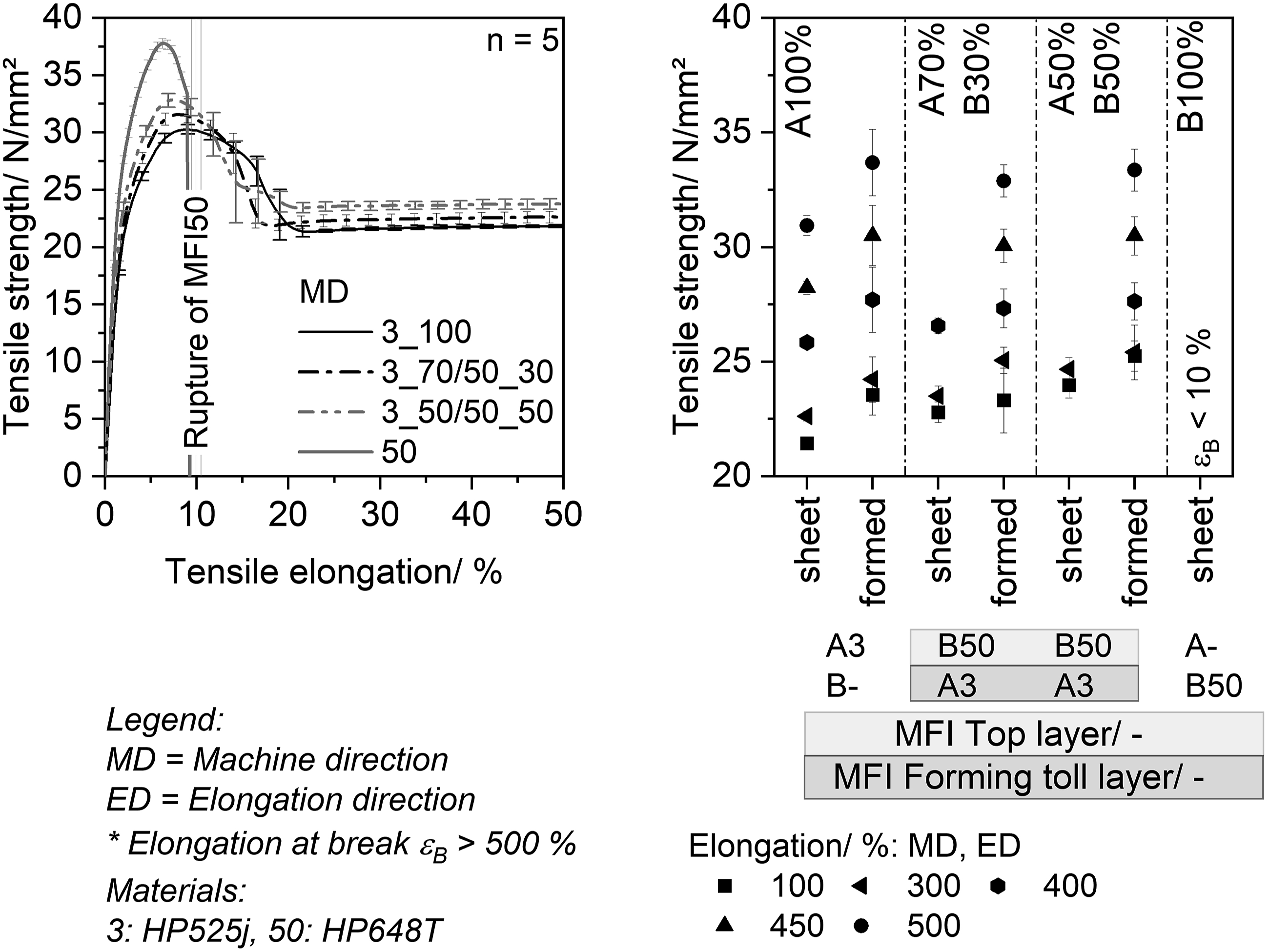
The stress-strain curve for the monolayer MFI-3, as well as for the 2-layer sheets, shows a similar and typical behavior for PP. In contrast the monolayer MFI-50 already fails in a brittle mode directly after reaching the yield stress due to the shorter molecular chains and thus exhibits a behavior similar to highly degraded material. After reaching the yield stress, the tensile strength decreases to (approx. 23 N/mm2 - 25 N/mm2) and remains constant until the strain hardening is reached (beginning at approx. 300% elongation). The results of the mechanical test show that the thermoformable material (MFI-3) is also the determining factor for the tensile strength, (see Figure 11 right). The results from the thermoformed parts show slightly higher tensile strengths than those from the non-thermoformed sheets which can be explained by the molecular orientation caused due to the stretching process during thermoforming. The thermoformed samples of MFI-3/MFI-50 behave similarly to the thermoformed monolayer MFI-3 regardless of the layer ratio. Further investigations should be carried out with respect to the tensile strength at break as well as the direction perpendicular to extrusion and perpendicular to elongation direction. However, it seems that using a non-thermoformable material does not affect the mechanical properties as the elongation at break remains greater than 500%.
Conclusion and outlook
This investigation examined how unprocessable materials as a monolayer when used in multilayer sheets impact wall thickness distribution and mechanical part performance in thermoformed sheets. In general, while non thermoformable material influences the wall thickness distribution, the mechanical properties of PP multilayer sheets were not greatly influenced by thermoforming process.
The complete wall thickness distribution shows a layer position and the percentage of the stable thermoformable material influences the part quality for cuboid truncated thermoforming tools. If a high percentage of a stable material is used (MFI-3, 70%), the wall thickness change is independent of both, the stable position and the used non thermoformable material (MFI-22/MFI-50). The wall thickness variability remains the same for both layer configurations. With equal thermoformable and non thermoformable layers, there is a small dependence on the layer position of the thermoformable layer and on the non thermoformable component (MFI-22 or MFI-50). If the thermoformable material (MFI-3) is close to the tool, the influence of the unstable material (MFI-22) can be compensated. If the non thermoformable material (MFI-22) is close to the tool, the thermoformable material (MFI-3) can not compensate the unstable material (MFI-22). However, if MFI-50 is used as an unstable layer in an equal layer distribution, the instability of this material can no longer be corrected by the stable layer position.
The mechanical properties of the thermoformed parts obtained in this investigation shows that thermoforming materials that are not thermoformable in a monolayer by using a multilayer sheet does not influence the part performance in a negative manner, even if some wall thickness deviations are higher than 30%. Considering that mechanical part performance can compensate certain wall thickness inhomogeneity, it is worth considering whether the wall thickness deviation limit can be extended for such materials in particular, so that more materials can be used in the thermoforming process, thus expanding the range of materials used for thermoforming significantly. The results obtained in this study indicate an enormous potential to use multilayer sheets in thermoforming for processing degraded materials and thus contribute significantly to expanding the material range in thermoforming as well as an increase in resource efficiency. Extending the limit offers the possibility to increase recycled materials in vacuum forming without performance loss. Further investigations that use recycled material should consider if these materials contain impurities such as particles or other polymers influencing the elongational properties.
Footnotes
Acknowledgement
The authors would like to thank the AiF-ZIM for their financial support. The authors would also like to thank the project partners COLLIN Lab & Pilot Solutions GmbH, Maitenbeth Germany, REKU Thermoforming Reckermann GmbH, Vlotho, Germany and Sysplast GmbH, Nuremberg Germany for their support. Furthermore, the authors are grateful to LyondellBasell, Industries N.V, Rotterdam, The Netherlands, and Avient Corporation formerly Clariant Masterbatch, Performance Masterbatches Germany GmbH, Lahnstein, Germany for providing the material.
Declaration of Conflicting Interests
The author(s) declared no potential conflicts of interest with respect to the research, authorship, and/or publication of this article.
Funding
The author(s) disclosed receipt of the following financial support for the research, authorship, and/or publication of this article: This work was supported by the cooperation project, Mehrschichtfolien zur vermehrten Post-Consumer Recyclatverarbeitung im Thermoformen – ReCoTherm“ (funding code KK5059901EB0) is funded by Zentrales Innovationsprogramm Mittelstand (AiF-ZIM) supported by Federal Ministry for Economic Affairs and Energy.
Biographies
Lisa-Maria Wittmann, M. Sc. Studied mechanical engineering at Friedrich-Alexander University, Erlangen-Nuremberg and has been working as a research assistant at the Institute of Polymer Technology since 2017. Her main research area is processing modified materials in thermoforming.
Since 2009 Prof. Dr.-Ing. Dietmar Drummer is the head of the Institute of Polymer Technology at University of Erlangen-Nuermberg. The Institute of Polymer Technology covers a broad field of polymer engineering with its main research areas as for example Additive Manufacturing, Processing, Joining Technology and Tribology and New Materials. In addition, Professor Drummer is KeyLab coordinator for the Bavarian Polymer Institute (BPI), Fürth, Germany