
Abstract
Multilayer sheets were used for thermoforming non thermoformable polymers in order to face the challenge of semi-crystalline polymers like low melt-stiffness. Mono- and 2-layer sheets consisting of different polypropylene (PP) homopolymers were extruded on a twin screw extruder. The PP viscosity as was measured by melt flow rate (MFR) 3 g/10 min., 12 g/10 min., 22 g/10 min. and 50 g/10 min. The layer ratio was varied between the equal layer ratio (A50/B50) of the individual layers and the low (A30/B70) or high viscosity ratio (A70/B30). The extrusion results show that for extreme viscosity differences (MFR3 and MFR50), the critical layer ratios known from the literature are only valid to a limited extent. The critical viscosity ratio < 4, which is known from the literature, is much lower here and should be less than 3.
The investigation of thermoformability on laboratory scale of the extruded PP sheets with different viscosities showed that the low viscous layer position has only a marginal influence on the general thermoformability. Thermoforming of materials that are not thermoformable, with a storage modulus of less than 10³ Pa and a ratio between storage and loss modulus (tan δ) greater than 1, becomes possible using a multilayer sheet independant of the layer ratio. If the layer with higher viscosity acts as a stabilizing layer, thermoforming is possible.
Introduction and state of the art
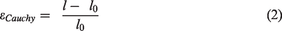
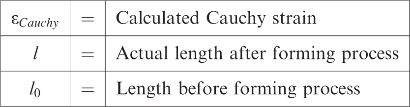
Thermoforming along with extrusion and injection molding belongs to the oldest polymer processing technologies. 1 In the thermoforming process, a flat sheet is formed into a three-dimensional part via temperature and pressure or vacuum. The process is generally divided into a heating phase, a forming phase using compressed air or vacuum, a subsequent cooling phase and demolding. 2 Typical thermoformed parts are known from the packaging industry and the field of technical transport packaging. 3 Polyolefins like polyethylene (PE) or PP that are the main polymers used and that are available in many grades 4 frequently used in thermoformed applications. The strains resulting from thermoforming can be described by using Cauchy or Hencky strain. 5 Since thermoforming has been an established process to produce three-dimensional parts from sheets for many years, there are material parameters which are used to estimate the thermoformability. So, for example, the extensional viscosity should be between 104 and 108 Pas. 6 , 7 Based on dynamic shear experiments, good thermoforming materials are those with storage modulus and loss modulus equilibrium occurring at a frequency whose inverse is approximately equal to the forming time. 8 The storage modulus should not be less than 103 Pa.
The main challenge in thermoforming semi-crystalline polymers is their low melt stiffness. 9 Low melt stiffness can cause excessive sagging. This tendency to sag has been investigated by many authors. It is known that for entangled melts, a viscosity increase occurs due to broad average molecular weight. 10 The greater the ratio between storage and loss modulus (tan δ) in the molten state, the more sagging will occur. 11 To increase the melt stiffness and to prevent extensive sagging, an increase in the zero-viscosity is necessary. Thus, to reduce the tendency to sag in thermoforming, PP with low melt flow indices should be used as the longer molecular chains can cause more entanglements during the heating phase. 12 Another possibility to increase the melt stiffness is to use chain extenders like peroxides. 13 Here, the enhancement achieved in the thermoforming process is directly related to the degree of long-chain branching. The investigation further indicates that the peroxide content has a significant influence on crosslinking. 14 Long chain branching is a possibile way to increase the strain hardening during extensional stress.15,16
While there are several studies dealing with ideal material parameters for thermoforming, there are only a few studies focusing on the thermoforming multilayer sheets. Multilayer sheets are predominantly used, for example, to create barrier properties against oxygen or water and to improve the sheet mechanical or optical properties. 17 Investigations in the field of thermoforming of multilayer sheets mainly focus on the packaging sector. For example, Crippa et al. 18 examined the properties of thermoformed multilayer sausage packaging consisting of different materials like PP, polyamide 6 (PA 6) and low-density PE (LDPE). The results show that the oxygen barrier is reduced and the brightness decreases due to the stretching process. 18 High strain rate studies on the strain behavior of Ethylene vinyl alcohol (EVOH) and Ethylene vinyl acetate (EVA) show that overall more homogeneous deformation can be achieved for EVA over a wider strain rate range, as the EVOH tends to neck. 19 Buntinx et al. 20 confirmed that the reduction of the volume-related mass transfer coefficient is proportional to the wall thickness reduction. 21 Badeka et al. 22 is dealing with the influence of LDPE waste in multilayer sheets. This investigation shows that 40–50 weight-% LDPE scrap has no influence in migrational, barrier or mechanical properties. 22
To produce a sheet for thermoforming, extrusion is used as continuous manufacturing process. 17 In general, materials with a viscosity greater than 100 Pas can be extruded. 23 In multilayer extrusion the viscosity significantly influences the layer distribution. Flow instabilities can occur at the interfaces between different viscous materials. These instabilities take either a wave-like pattern or encapsulation and are affected by the die geometry. 24 The less viscous material flows around the high viscous material. Han et al.20,25 did some initial investigations on how viscosity influences the flow process in multilayer sheet extrusion. The investigations showed, among other things, that the velocity distribution, the shear rate profile and the shear stresses can be predicted by rheological properties of the individual materials. 25 In order to prevent waviness instabilites the major-minor stream layer viscosity ratio should be smaller than 2:1. 26 It should be noted that the melt streams used in this investigation were based on the same LDPE. The extent to which flow instabilities affect the layer quality due to excessive viscosity differences in multilayer sheets was examined. For LDPE and polystyrene (PS), Han et al. 20 showed stable and unstable flow ranges in multilayer sheet extrusion depending on thickness distribution and skin to corelayer viscosity ratios. For low thickness ratios as well as for high viscosity differences, unstable ranges form. 20 Dooley 27 focused on flow instability development in multilayer sheet extrusion. Thereby, the difference in individual component’s viscosity should be as small as possible (<4) to prevent encapsulation phenomena. 27 To evaluate flow processes in multilayer systems is, in general, a challenge. 28 In extrusion processing polymers with a broader molecular weight distribution develop instabilities more quickly whereby the development also depends on the layer ratio. In materials with narrow molecular weight distribution, instabilities arise from the existing interfacial stresses. Wave-shaped instabilities orginate from extensional deformation of the minor layer at the merge point, whereby the viscoelastic properties of the adjacent layer influence instability development. 29 The elongational rheological properties thus significantly influence the development of strain instabilities. While strain-hardening behavior in thermoforming is positive for part quality, strain-hardening melt is more likely to lead to interfacial instabilities. 30
As PP is processed and gets degraded, less viscous materials arise, which thus lead to greater differences in viscosity when processing multilayer sheets in extrusion. As degradation is an important process in polymer processing many publications deal with how polymers age focusing the rheological parameters. Incarnato et al. 31 for example found a relation between viscosity decrease and molecular weight for recycled PP. The viscosity decreased because the molecular weight decreased and the molecular weigth distribution narrowed. 31 The cross-over point location is an indicator for chain length and molecular weight.4,32 For a narrow molecular weight distribution, the cross-over point shifts upward, while a wider molecular weight distribution causes a downward shift. However, the cross-over point shifts to the left for long or branched polymer chains. With shorter or less branched polymer chains, the cross-over point shifts to the right. 33 The dominant PP degradation mechanism is chain scission which leads to a lower viscosity, 34 in PE chain branching and crosslinking reactions occur. 35 The chain scission is dependent on the molecular weight, especially at higher molecular weights. 36 A classification is made between use-induced and processing-induced degradation mechanisms as for example high shear rates and processing temperatures. 37
Extruding materials with different viscosities and thermoforming materials with low melt stability are a major challenge. This investigation aims to enable non thermoformable materials, such as recycled items, to be suitable for the thermoforming process by using a multilayer sheet structure. A multilayer sheet may create a stabilizing layer that prevents the sheet from sagging, so that thermoforming should be possible without modifing the material. PPs with different viscosities, which are used for extrusion and thermoforming as PP is commonly used in thermoforming processing, were investigated in this study. For this investigation, two-layered sheets with different layer thicknesses were thermoformed.
Material
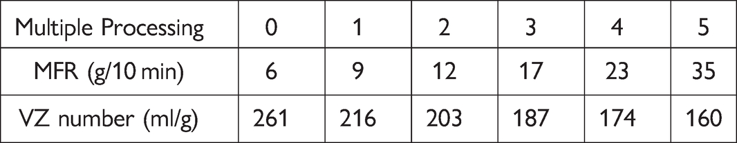
In order to simulate the influence of polymer degradation, thermal degradation was generated using multiple compounding. The PP homopolymer [HP501L, provided by LyondellBasell (Industries N.V., Rotterdam, The Netherlands)] was compounded multiple times in a twin screw extruder (Leistritz Extrusionstechnik GmbH, Nuremberg, Germany). The material was reprocessed with a 240°C nozzle temperature and at 7 kg/h volumetric flow rate. The selected temperature profile was based on typical PP processing parameters.36,37 Table 1 shows the MFR and viscosity (VZ) obtained for multiple compounding from 0 to 5 times. The VZ number provides information about the rheological behavior of a material. A low viscosity number can be considered equal to a high flowability. A decrease in the average molecular weight due to multiple processing can be also be indicated by a decreased VZ number.
PP degradation after multiple processing as measured by MFR and VZ number.
Multiple processing is used to evaluate the influence of multiple processing and to select virgin grades based on MFR and VZ number. For the following investigations of extrusion and thermoforming, different virgin homopolymer PPs supplied by LyondellBasell (Industries N.V., Rotterdam, The Netherlands) are selected. Table 2 lists the PP homopolymer grades, MFR, density, peak melting temperature, the abbreviations chosen for the following investigation and the corresponding number of multiple processing.
Used materials, corresponding MFR values and abbreviations.
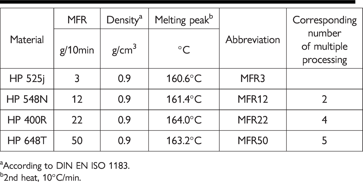
According to DIN EN ISO 1183.
2nd heat, 10°C/min.
Providing an initial material categorization, melt flow was measured. The data sheet MFR was confirmed by measurements at 230°C and 2.16 kg. The HP525j with the lowest MFR value is designated as MFR3, and HP648T with the highest MFR value is designated as MFR50. All homopolymers have the same density. The melting peak temperature is between 160°C and 164°C.
To identify the separate layers from each other, one layer was colored with a yellow masterbatch pigment [REMAFIN-PE-GELB TIRN from Avient Corporation formerly Clariant Masterbatch (Performance Masterbatches Germany GmbH, Lahnstein, Germany)]. The yellow colour used does not affect either the heating or the elongation behavior.
Experimental set-up
Sheet extrusion
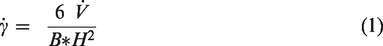
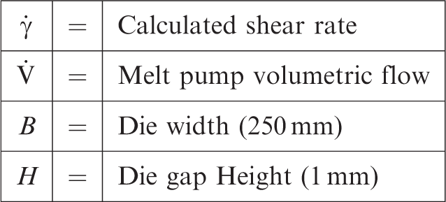
Melt pump settings and corresponding shear rate values extruded at 180°C die temperature.
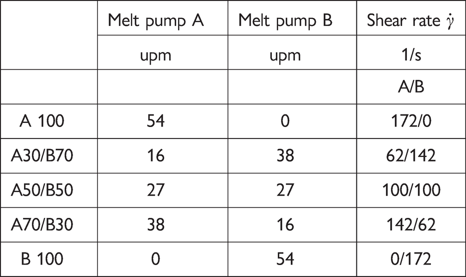
Table 4 summerizes the produced sheet configurations with the layer ratio A50/B50, A30/B70, A70/B30. Here, A30/B70 means that the layer thickness of layer A is 150 µm and layer B is 350 µm. A50/B50 is equal to 250 µm for each layer.
Overview of the layer configurations extruded at 180°C die temperature.
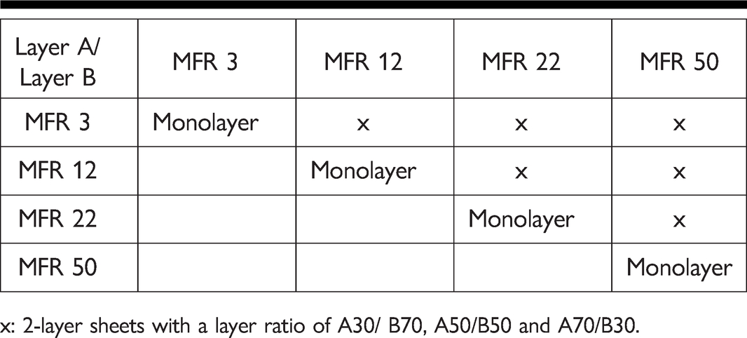
x: 2-layer sheets with a layer ratio of A30/ B70, A50/B50 and A70/B30.
To evaluate how a stable single layer’s position influences the thermoforming process, layer A and layer B were made from resins with different viscosities. In case the materials of type HP525j and HP548N are coextruded, for example, the nomenclature MFR 3/MFR 12 is used in the following.
Thermoforming
Thermoforming was performed on a single-station vacuum forming machine Berg Mini M3 (Berg Engineering GmbH, Berlin, Germany). Cylindrical, rotationally symmetric, aluminium male thermoforming tools were used for testing. The tool has an average surface roughness Rz of 14 μm that was measured with the roughness tester Surtronic 10 (Taylor-Hobson, AMETEK, Inc., Weiterstadt, Germany). The tool speed was approximately 140 mm/s and the tool temperature was 80°C for all investigations which is a standard tool temperature for processing PP. 1
Upper and lower quartz radiant heaters (type SQE 80x60, 150 W; Friedr. Freek GmbH, Menden, Germany) heated the PP sheet to its 180°C forming temperature. The heating process was controlled by a pyrometer (type 22MID10LTCB3; Schlender Messtechnik e.K., Berlin, Germany). After forming, a 10 second cooling time followed. In order to evaluate the wall thickness and strain distribution, an areal draw ratio of 2.5 (which corresponds to an 80 mm tool height) was applied. The average theoretical wall thickness reduction can be calculated by the quotient of the area of the sheet without clamping area and the surface of the thermoforming tool multiplied by the sheet thickness. The theoretical wall thickness reduction is 70% for this tool.
Figure 1 shows the sheet preparation with the raster, the clamping direction in the thermoforming machine, the selected part characterization as well as the geometric dimensions of the thermoforming tool and the layer orientation during the thermforming process.
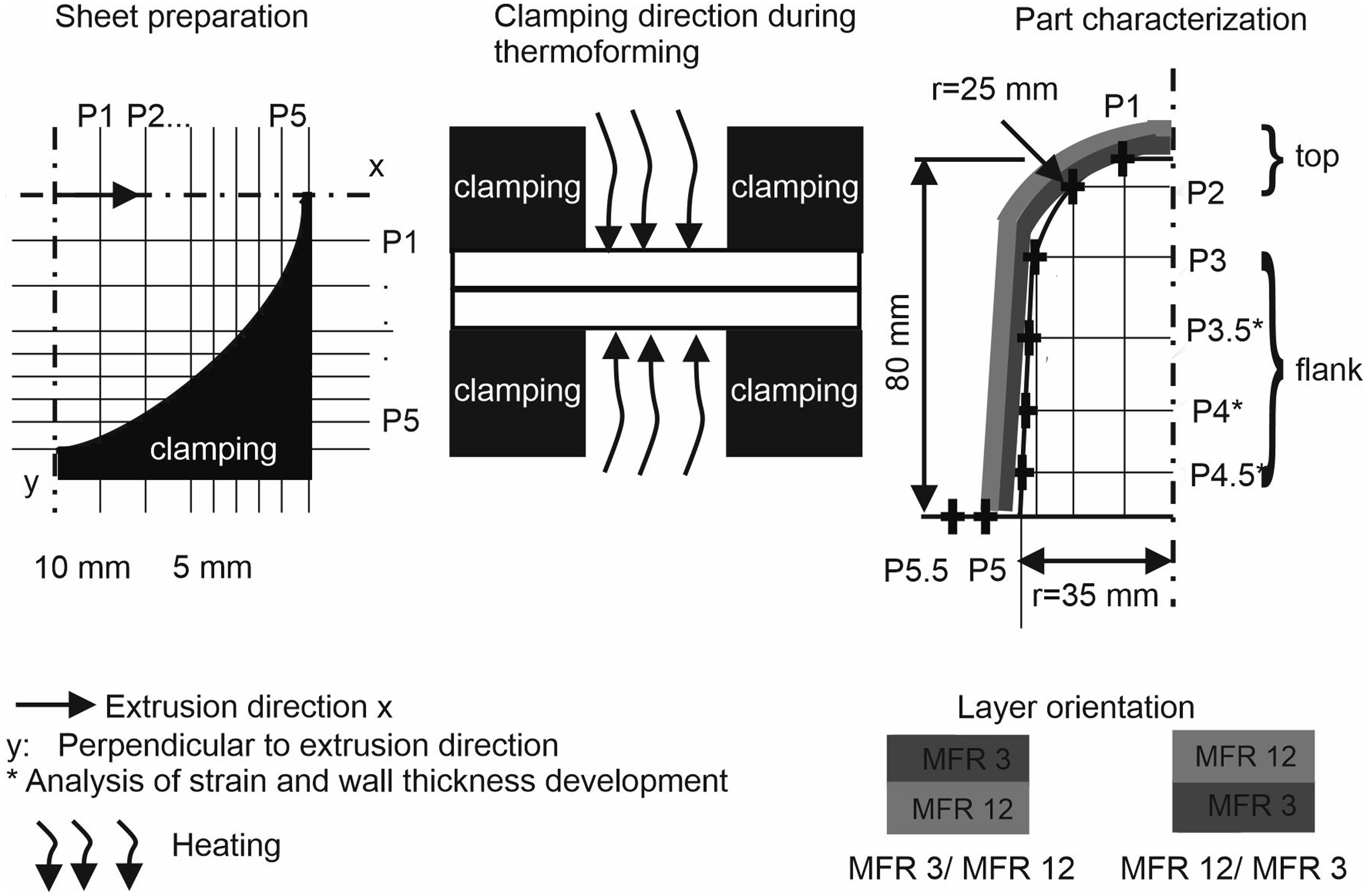
Schematic illustration of the sheet preparation with raster segments, the thermoforming process and the analysed thermoformed part with tool specification.
The geometrically defined elongation distance (P0 – P5.5) given by the forming tool is 120 mm. In thermoforming, the same nomenclature as in extrusion is used. Here, the material facing away from the forming tool is placed first and the material close to the forming tool is second. So for example MFR 3/ MFR 12 means that HP 525j is far from the tool and HP 548N contacts the tool.
Characterization
General PP homopolymer characterization
Rheological analysis to compare the different PP homopolymers
A Discovery HR-2 plate-plate rheometer (TA-Instruments, Inc., Waters Corporation, Hüllhorst, Germany) was used to rheologically characterize the polymers. A pellet is clamped between two axially symmetrical rotation plates with a defined preload. One plate is fixed, while the opposite plate can rotate. The rotating plate is subjected to a rotational or oscillatory movement, which induces a corresponding drag flow in the polymer. Detection the stress response enables interpretating the viscoelastic properties of the polymer melt. With the rheological measurements, different material characteristics can be determined or mapped depending on the operating mode. In the following investigation, the measurements are carried out in the molten state at 170°C, 180°C and 200°C. The temperature selection is based on the parameters used during extrusion and thermofoming. The measurements were made from 0.1 rad/s to 500 rad/s.
Determination of the VZ number
VZ number or the reduced viscosity was measured to characterize the molecular structure. The VZ number was determined according to DIN EN ISO 1628–3:2010 with an AVS 350 Ubbelohde viscometer (Schott Instruments GmbH, Germany). A Decalin-Irganox solution was the solvent. The PP was disolved for 60 minutes at 150°C in a heated oven.
Characterization – Extrusion processing
Rheological analysis – Shear rate dependent viscosity
Since, among others, the viscosity ratio between the individual layers is important in multilayer extrusion, high-pressure capillary rheometer measurements were first performed to determine rheological parameters related to the extrusion processing. The analysis of the shear rate dependent viscosity was carried out with a counterpressure Rheograph 75 (Goettfert, Werkstoff Prüfmaschinen GmbH, Buchen, Germany) with a 10 mm piston diameter. Since at 180°C the MFR 3 was still too viscous for the capillary rheometer tests, a die temperature of 190°C was selected in order to be able to compare all materials. This temperature corresponds more or less to the die temperature during extrusion. After the measuring chamber was heated to the test temperatures for 600 s, the polymer pellet was filled in several steps. Manual compression and degassing ensured a completely filled chamber without air inclusions. The ram speed was adjusted to obtain the desired shear rate.
Optical analysis – Extruded sheets
The sheets were photographed with a Canon EOS 5DS R (Canon Kabushiki-gais; Krefeld, Germany). In order to analyse the layer thickness distribution over the cross section linearly polarized light microscopy (0°) was used. For thickness distribution analysis 10 µm cross sections were made perpendiular to the extrusion direction. The cross section was first embedded in epoxy, then ground and polished. Afterwards, the cross sections were analyzed with an Axio Imager.M2 microscope (Carl Zeiss AG, Oberkochen, Germany) at 100x magnification. The images were made using the objective EC Plan-Neofluar 10x/0.25.
Characterization – Thermoforming processing
Rheological analysis – Thermoforming processing
The rheological characterization for thermoforming suitability is carried out that same as for different PP homopolymers. Shear modulus and tan δ were evaluated at 1.5 rad/s, that corresponds to the forming step time.
Chauchy strain analysis
Wall thickness developement
The wall thickness distribution was evaluated at the same points as the strain development and was measured before and after thermoforming with a Magna-Mike 8500 thickness gauge measurement system (Olympus Deutschland GmbH, Hamburg, Germany), which uses the Hall effect to determine the thickness of non-magnetic materials. Cross sections to evaluate the thickness distribution were taken at P4.5.
Optical analysis – Thermoformed parts
The thermoformed parts were also photographed. The cross sections were taken in the most elongated area of the thermoformed part (P4.5). These images were used to measure the layer thickness after the thermoforming process. The advantage of the cross sections is the possibility to measure the total thickness reduction, as well as the thickness reduction of the individual layers. All devices used are described above.
Results and discussion
PP resin analysis
Cross-over point – Rheological analysis
Since a polymer’s molecular structure is a major factor for processability and a shift in the cross-over point indicates a molecular change in the polymer,4,32 the fundamental material characteristics are discussed first. Figure 2 shows the basic characterization of the materials applied for investigation, whereby Figure 2 (left) depicts the storage and loss modulus curve of the selected materials at 180°C. Figure 2 (right) summarizes the cross-over point shift at the cross-over point frequency ωc.
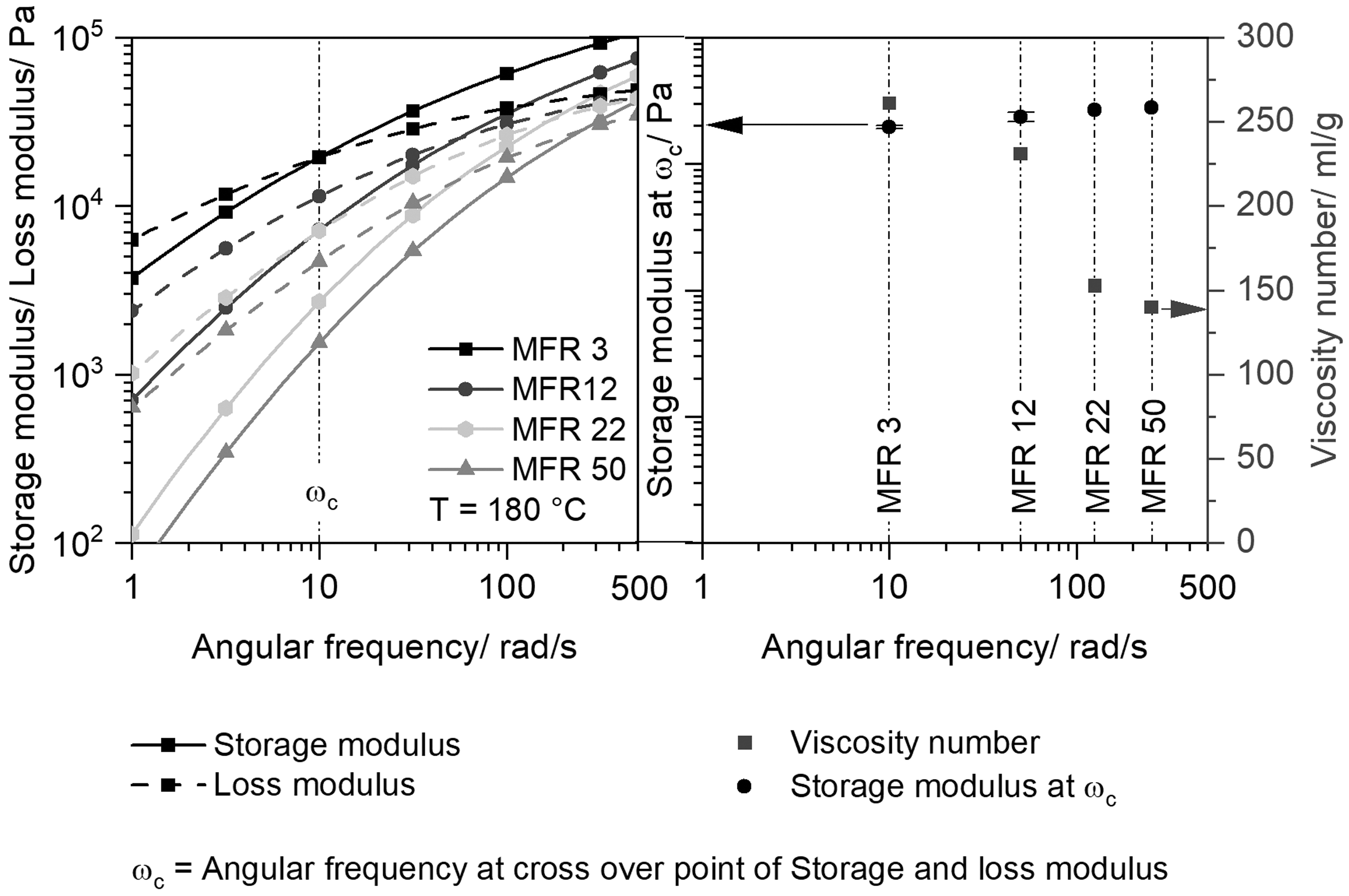
Storage and loss modulus for (MFR 3, MFR 12, MFR 22, MFR 50) at 180°C (left), storage modulus at cross-over point and VZ number (right).
As MFR 3 is, according to data sheet information, a typical thermoforming material, it is used as a reference. The MFR 3 cross-over point is further to the left (ωc = 10 rad/s) when compared to MFR 12, MFR 22 and MFR 50. It could be concluded that MFR 3 has longer molecules than MFR 12 (ωc = 50 rad/s), MFR 22 (ωc = 125 rad/s), and MFR 50 (ωc = 250 rad/s). However, this is only a qualitative statement. Since longer chains are more suitable for thermoforming,12,17 as for example sagging during the heating phase is reduced and strain-hardening behavior is induced, MFR 22 and MFR 50 are probably rather less suitable for thermoforming in a single layer as the rheological analysis suggest.
VZ number
Besides the cross-over point, the VZ number is a parameter for the polymer’s average molecular weight. Figure 2 (right) shows the VZ numbers. One sees that there is a continuous decrease in the VZ number for the PPs used. While the MFR 3 VZ number is 260 ml/g, the MFR 50 VZ number is only 140 ml/g. A decrease in the VZ number indicates the decrease in the average molecular weight. However, as the results from the cross-over point of storage and loss modulus and the VZ number are only indicators, it is important to perform gel permeation chromatography in further investigations to determine the molecular weight and the molecular weight distribution.
Results – Extrusion process
Shearflow behavior
Since, especially in multilayer extrusion, the flow behavior of the individual polymers significantly contributes to the layer thickness distribution and thus determines the sheet quality, the shear rheological measurements are discussed first. Figure 3 presents the high-pressure capillary rheometer measurements, on the PP granulates. They show a decrease in viscosity with increasing MFR and shear rate.
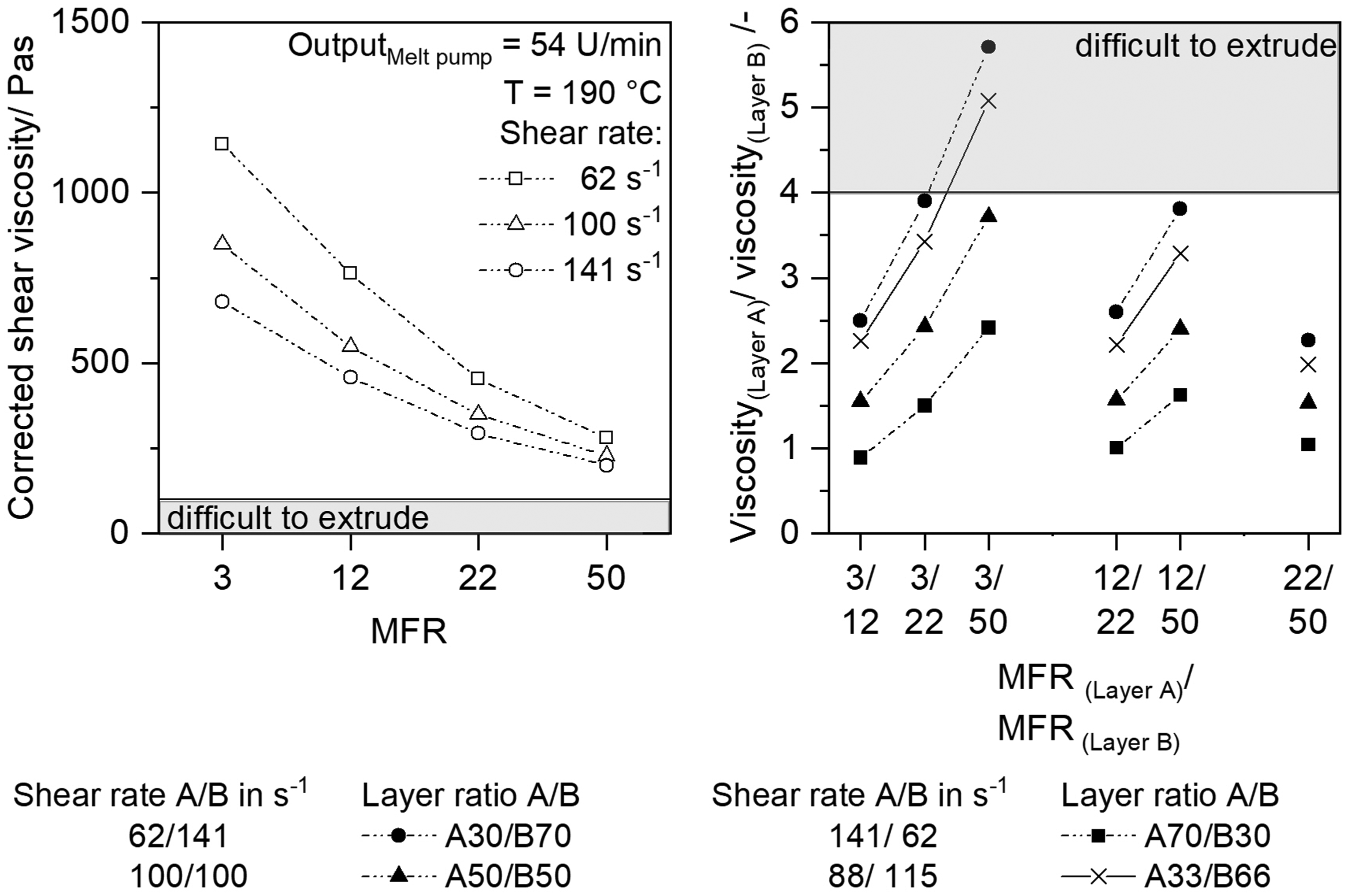
Shear viscosity for (MFR 3, MFR 12, MFR 22, MFR 50) at 190°C (left), viscosity ratio of layer A and layer B (right).
All resins were extrudable at 190°C, as the viscosity is still above 100 Pas. For the A50/ B50 layer ratio, which is at a shear rate equal to 100 s−1, the viscosities are listed in the following as examples: 850 Pas for MFR 3 550 Pas for MFR 12 350 Pas for MFR 22 230 Pas for MFR 50
At a lower shear rate ( 1142 Pas for MFR 3 281 Pas for MFR 50
At a higher shear rate ( 680 Pas for MFR 3 200 Pas for MFR 50
To evaluate the extrusion process stability the viscosity ratio is determined. The layer A viscosity is divided by the layer B viscosity, and layer B is always the less viscous material. Figure 3 (right) shows the viscosity ratio for the layer configurations. One recognizes that with increasing viscosity difference, the layer configurations that can be extruded decreases. For example, extruding MFR 3/MFR 22, MFR 3/MFR 50 and MFR 12/MFR 50 is not possible with a layer distribution of A30/B70 as the viscosity ratio is greater than 3. Also, extruding the MFR3/MFR 50 combination is only possible to a limited extent with a A50/B50 ratio as the MFR 3/MFR 50 viscosity ratio is 3.7, which is close to unstable extrusion .26,30 One concludes that as the stable layer proportion decreases the extrusion becomes more unstable.
Figure 3 (right) also shows that the viscosity ratios equalize further when materials with similar viscosities are used, so that even when combining less viscous materials, no restrictions are expected in extrusion. For example, the MFR 3/MFR 12, MFR 12/MFR 22 and MFR 22/MFR 50 viscosity ratios and the A70/B30, A50/B50 and A30/B70 layer distributions are similar, being between 1 and 2.6. As these viscosity ratios are well below 4,20,27 stable extrusion can be expected independent of the layer ratio. This ratio can be taken as a guideline, which gives some insight to the general processability. The 2:1 layer ratio guideline (A33/B66) for stable extrusion originates from a publication by Martyn et al., 26 who processed a two-layer LDPE sheet with the same LDPE at 200°C 26 and can not be confirmed according to this investigation.
A general comparison of the extrusion studies is quite difficult as the mass flow, the die geometry or the angle at which the two flows merge significantly influence instabilities. The material selection has a major influence on the extrusion process. For example, Han et al. 20 processed PE and polystyrene (PS) in 3- and 5 layer sheets, respectively, Martyn et al. 26 used LDPE, and Dooley 27 extruded high impact PS, LDPE, and polycarbonate.
Optical analysis – Extruded sheets
To check whether reproducable layer distributions can be achieved with the adjusted process parameters, cross sections from the middle of the sheet, [See Figure 4 (right)], were made.
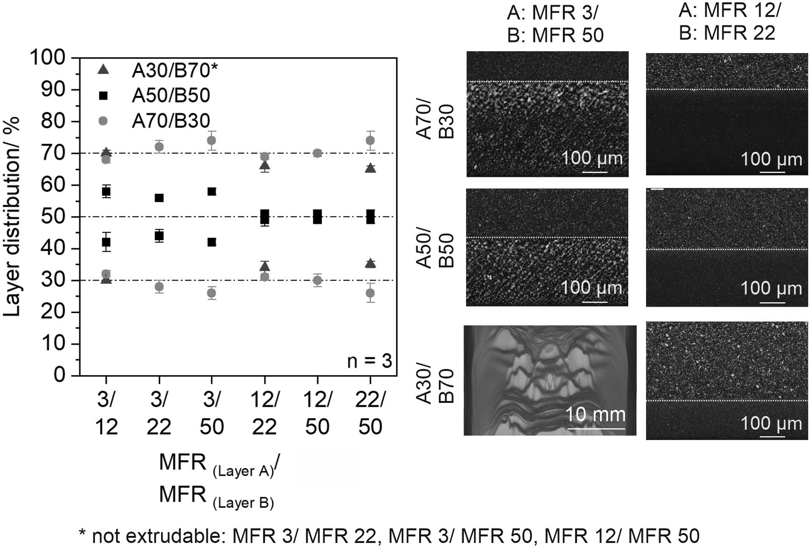
Layer distribution percentage (left) and representative thin slices of the extruded sheets with a layer ratio of A30/B70, A50/B50, A70/B30 as well as waviness instabilities (right).
Layer thicknesses of each single layer of the multilayer sheets were measured on the cross sections and the layer distribution percentage was calculated. The desired layer distribution could be achieved for all configurations. Figure 4 (left) shows that with decreasing viscosity differences the single layer distribution becomes more homogenous. Especially for ratios above 3, it is noticeable that the encapsulation phenomenon – the more viscous material flowing to the edge – by the more viscous material already starts to a small extent (see MFR 3/MFR 50, A50/B50). The layer distribution in the middle of the sheet for MFR 3/MFR 50 is closer to A60/B40 than A50/B50.
Figure 4 also shows possible occuring surface defect patterns such as wave-like instabilities (MFR 3/MFR 50, A70/B30), which are probably caused by flow instabilities in the die land 24 and which can arise from extensional deformation of the minor layer at the merge point, with the viscoelastic properties of the adjacent layer influencing the instability development. 29 No cross sections on the edges are shown as no significat influence on the layer distribution homogenity could be found in this investigation. Considering the morphology, a finely spherulitic structure is noticeable in the pigmented layer. Since it is known from the literature that a fine spherulitic morphology has a rather positive effect on the thermoformability and overall, more homogeneous deformations due to less necking occur, 38 the nucleating effect resulting to the pigmentation will not be investigated in more detail in this study.
Results – Thermoforming process
Qualification of the thermoforming behavior by rheological measurements
To estimate how suitable the materials are for thermoforming, the stiffness in the heating phase was evaluated with a plate-plate rheometer. Figure 5 depicts the storage modulus and tan δ at 170°C, 180°C and 200°C.
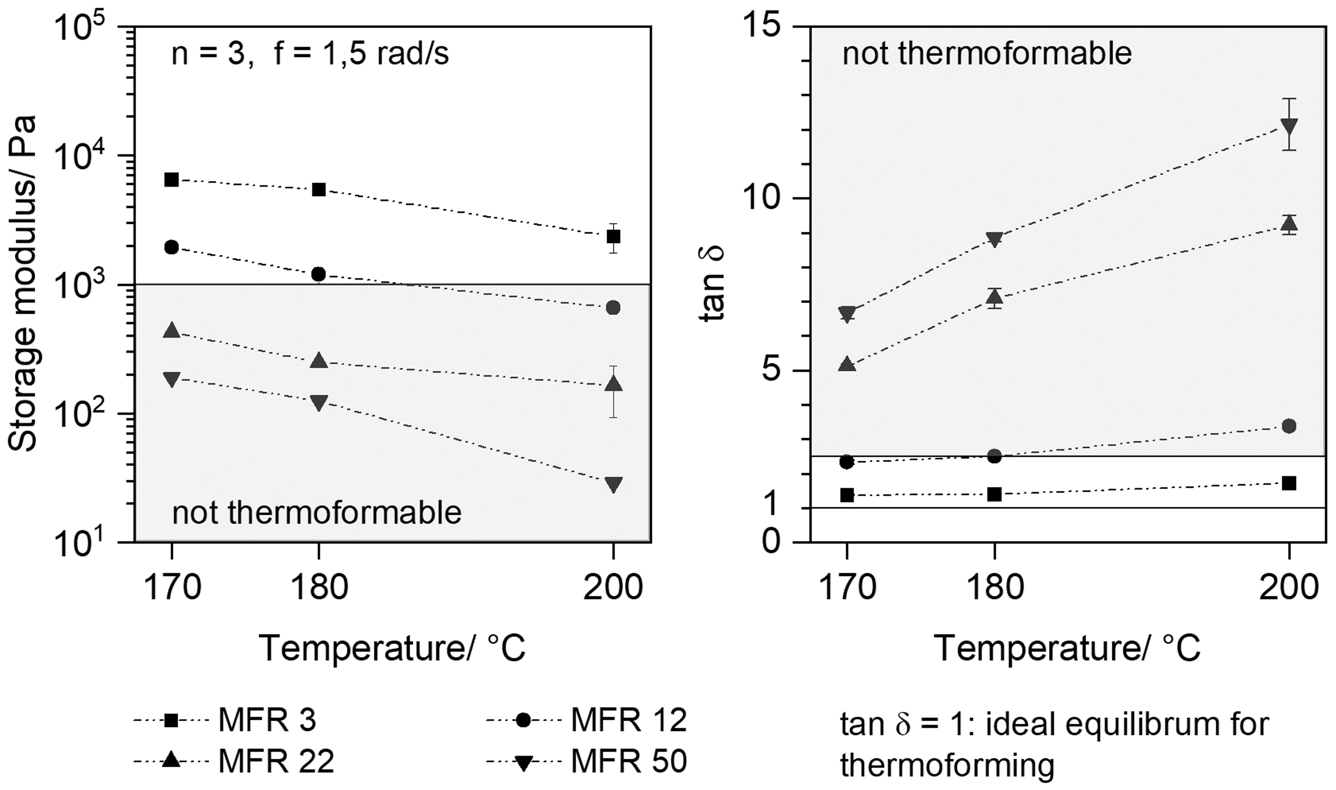
Storage modulus (left) and tan δ (right) for (MFR 3, MFR 12, MFR 22, MFR 50) at 170°C, 180°C and 200°C.
MFR 3 is characterized by a storage modulus greater than 10³ Pas and a tan δ that remains constant over a wide temperature range and can thus be qualified as a thermoformable material. For example, its storage modulus at 170°C is 6500 ± 200 Pa and at 200°C it is 2355 ± 600 Pa. Looking at the MFR 12 storage modulus behavior, one sees that it is thermoformable over a smaller temperature range than MFR 3. The storage modulus in this case is also greater than 103 Pa between 170°C and 180°C. MFR 22 and MFR 50 are difficult to thermoform as their storage modulus is less than 10³ Pa and the tan δ is greater than 1.
11
At 170°C, the MFR 22 storage modulus is 15 times lower than MFR 3, and the MFR 50 storage modulus is up to 34 times lower. Comparing the literature data available, one sees that the materials used in the investigation of Lau et al.
11
showed a much more balanced ratio between storage and loss modulus compared to the materials used in this study. Evaluating the tan δ at the same frequency as Lau et. al.
11
gives a tan δ: 61 ± 3 for MFI 50 57 ± 0.9 for MFR 22 9 ± 0.7 for MFR 12. 3 ± 0.04 for MFR 3
This data confirms that MFR 22 and MFR 50 in particular are not suitable for the thermoforming process as single sheets.
Optical analysis of the thermoforming process
Since the forming accuracy of the thermoforming part is an important evaluation factor for quality, first of all photographs of the thermoformed parts are shown in Figure 6. Since no significant differences could be seen in the formed part, only the images of the parts consisting of monolayers and a layer ratio A50/ B50 are displayed.
While thermoforming was possible for the monolayers MFR 3 and MFR 12 at an areal draw ratio of 2.5, thermoforming of the monolayer MFR 22 and MFR 50 was not possible. Enormous sagging occured during the heating phase of MFR 22 and MFR 50 which in some cases led to tearing of the sheets, or wrinkles appeared on the cup of the parts during forming. This extreme sag causes the material to accumulate at the top of the cup. No improvement of the forming could be achieved for material MFR 22 and MFR 50 by shortening the heating time to minimize the sagging. An explanation for this can be found in the low melt stiffness, the low storage modulus and high tan δ of the materials (see Figure 5). The entanglement loosens during the heating phase and the sheet becomes unstable. 12
The thin cross sections (Figure 6) indicate uniform elongation of the individual layers for all configurations. Due to the elongation process during thermoforming, the final thermoformed sheet thickness is only 80% of the initial sheet thickness. One conludes that processing the non thermoformable polymers (MFR 22 and MFR 50) in a multilayer sheet such as MFR12/ MFR50 allows thermoforming.
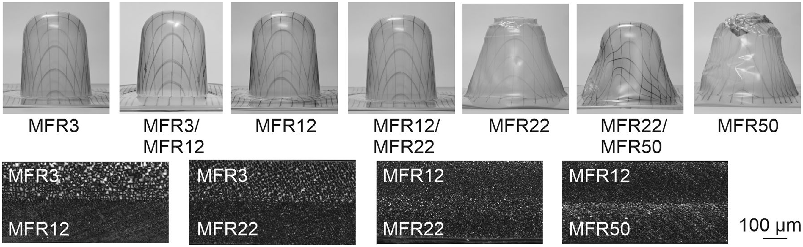
Images of the thermoformed parts (monolayer MFR 3, MFR12, MFR22, MFR50) and exemplary multilayer thin cuts at a layer ratio A50/ B50 of sheet configuration MFR 3/ MFR 12, MFR 3/ MFR 22, MFR 12/ MFR 22, MFR 12/ MFR 50 after the forming process of P 4.5.
Strain and wall thickness analysis of the thermoformed part
In addition to optical analysis, strain and wall thickness changes were also analyzed. Figure 7 shows the relationship between the strain and wall thickness distribution.
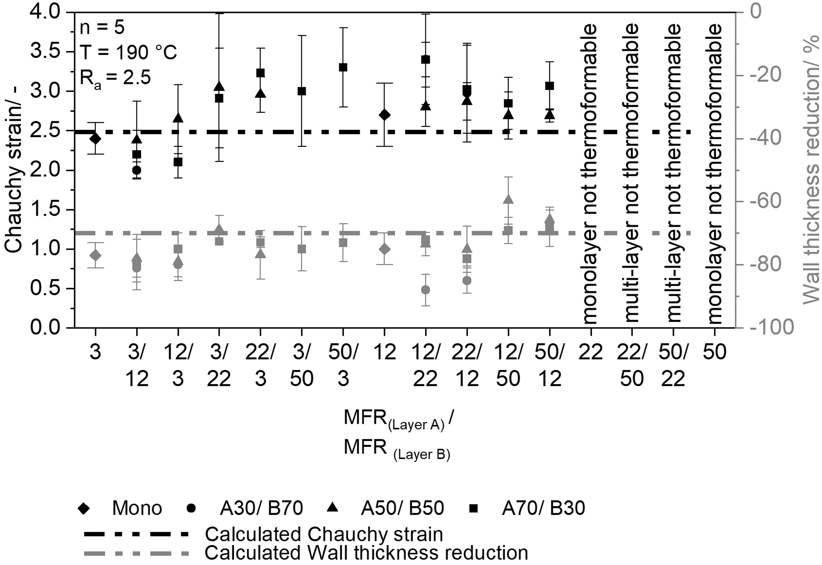
Measured strain and wall thickness after the forming process at P 4.5.
Due to the rotationally symmetric geometry, the strains in all directions are identical, so that for clarity Figure 7 shows only the resulting strains perpendicular to extrusion direction. Regardless of the layer configuration, no stretching takes place in the top of the cup and the initial sheet thickness remains approximately the same, only the area between P3-P4.5 in the flank is evaluated. Comparing the strain given by the tool geometry and the strain actually occurring in the part, it is noticeable that they are approximately the same. Thus, the maximum strains are directly related to the tool geometry. Due to the high standard deviations, it is difficult to indicate definite tendencies. Overall, however, the elongation is less affected for the multilayer sheets.
The geometry-related wall thickness reduction is approximately 70% for all configurations. The individual layer configuration ratios do not seem to have a major influence on the resulting strain distribution in the part. This means that the presence of a thin thermoformable stabilizing layer already makes thermoforming of non-thermoformable materials possible. Whether the stable thermoformable layer is in contact with the tool or facing away from the tool does not have a major influence on the general thermoformability. A direct comparison with existing knowledge in the literature on multilayer sheet thermoforming cannot be made, since the investigations mainly focus on how stretching influences, for example, barrier properties.18,19,35 In this case, the influence of the thermoforming process is not evaluated.
Conclusion and outlook
The investigations indicate that viscosity is a significant parameter for producing different extruded layer configurations. The optical analysis confirms that choosing the right process parameters will provide the desired layer configuration. It might be possible to expand the number of sheet configurations by further adjusting the process parameters, such as output and temperature profiles. The < 4 viscosity ratio for the materials to be extruded postulated in the literature can be used only to a limited extent as a parameter in these investigations. For high viscosity differences the viscosity ratio should be less than 3 to extrude homogenous sheets. Significant differences between the individual layer viscositites require more viscous layer percentage to ensure stable extrusion without flow instabilites like waviness or encapsulating phaenomena. Thus, multilayer extrusion can be used as a suitable method for increased processing of less viscous materials as known from the recycling. To reduce the viscosity differences between the individual layers, a structure with more than three layers would be suitable, for example, through which a viscosity gradient can be specifically set.
The thermoforming results obtained in this investigation show that thermoforming materials that are not thermoformable in a monolayer can be become thermoformable by using multilayer sheets. This laboratory thermoformability investigation shows that the low viscous layer position has less influence on the general thermoformability, since both the wall thickness decreases and the strain changes are similar. The thermoformable layer prevents the extreme sheet sagging during the heating phase and thus the accumulation of material at the top of the tool. The material, which is not thermoformable or is difficult to thermoform (tan δ > 1, storage modulus <10³ Pa), is stabilized and uniformly shaped thanks to the thermoformable layer. Using multilayer sheets to thermoform not thermoformable materials, offers the potential for an increased use of recycled materials in vacuum forming that were previously unsuitable for thermoforming. In further investigations that use recycled material one has to consider if they contain any impurities such as particles or other polymers.
Footnotes
Acknowledgement
The authors would like to thank the project partners Dr. Collin GmbH & Co.KG, Maitenbeth Germany, REKU Thermoforming Reckermann GmbH, Vlotho, Germany and Sysplast GmbH, Nuremberg Germany for their support. Furthermore, the authors are grateful to LyondellBasell, Industries N.V., Rotterdam, The Netherlands, and also Avient Corporation formerly Clariant Masterbatch, Performance Masterbatches Germany GmbH, Lahnstein, Germany for providing the material.
Declaration of Conflicting Interests
The author(s) declared no potential conflicts of interest with respect to the research, authorship, and/or publication of this article.
Funding
The author(s) disclosed receipt of the following financial support for the research, authorship, and/or publication of this article: The cooperation project “Mehrschichtfolien zur vermehrten Post-Consumer Recyclatverarbeitung im Thermoformen – ReCoTherm” (funding code KK5059901EB0) is funded by Zentrales Innovationsprogramm Mittelstand (AiF-ZIM) supported by Federal Ministry for Economic Affairs and Energy. The authors would like to thank the AiF-ZIM for their financial support.