
Abstract
This article assesses the seismic design provisions for floor diaphragms per ASCE/SEI 7-22 Section 12.10.1 and Section 12.10.3, with emphasis on how these provisions account for the higher-mode effects on peak horizontal floor accelerations of earthquake-resistant buildings. A framework is developed for processing and analyzing strong-motion acceleration data from buildings monitored by the California Strong Motion Instrumentation Program (CSMIP), which is used to assess the floor diaphragm design acceleration coefficients in ASCE/SEI 7-22. These coefficients, which estimate peak floor accelerations at the design-level earthquake, are modified in this study to consider the intensity of measured ground motions and the level of earthquake-induced inelastic building response. First, the spectral response factors, defined as the ratio between the spectral response acceleration at a given floor and that at the ground, are evaluated at the second- and third-mode periods and compared with those at the first-mode period to assess the higher-mode effects. Then, two metrics are defined to compare the modified acceleration coefficients with the measured peak floor accelerations. The results confirm the need to consider the characteristic dynamics of the buildings to estimate the design forces for floor diaphragms. This consideration is included in ASCE/SEI 7-22 Section 12.10.3 but not rationally considered in Section 12.10.1. The modified acceleration coefficients based on ASCE/SEI 7-22 Section 12.10.1 can considerably underestimate the peak floor accelerations, whereas those based on Section 12.10.3 can capture the increased peak floor accelerations caused by the higher-mode earthquake-induced inertial forces. Thus, the authors recommend using ASCE/SEI 7-22 Section 12.10.3 over Section 12.10.1 to estimate the design forces for floor diaphragms; however, certain assumptions considered in Section 12.10.3 require further revision.
Keywords
Introduction
Earthquake-resistant buildings
Earthquake-resistant buildings are critical in safeguarding human lives and infrastructure in seismically active regions (Anderson et al., 2010; Belleri et al., 2015; Ghosh and Cleland, 2012; Henry et al., 2017; Iverson and Hawkins, 1994; Saatcioglu et al., 2001). Therefore, the development of seismic design guidelines for earthquake-resistant buildings is of paramount importance to society (ASCE/SEI 7-22, 2021; Kuramoto, 2006; NCh433, 2016; NZS1170.5, 2004). These guidelines have continually evolved to ensure the structural safety and integrity of buildings, aiming to enhance their seismic performance, reliability, and resilience (FEMA P-58, 2018; Panagiotou and Restrepo, 2011; Priestley, 2000; Priestley et al., 2007). The enhancement of the seismic design guidelines has been possible thanks to the continued verification and validation of the assumptions and limitations considered in the design provisions.
The earthquake-resistant buildings typically comprise two systems: (1) the gravity load-resisting system and (2) the seismic force-resisting system (SFRS). The gravity load-resisting system resists the dead, live, and vertical earthquake-induced loads. This system typically consists of horizontal floors and gravity columns. The SFRS resists the horizontal earthquake-induced loads. The vertical elements of this system typically consist of walls, moment frames, braced frames, or a combination of these systems. Some earthquake-resistant buildings consist of only one system simultaneously acting as the gravity load-resisting system and SFRS. Those systems are named bearing systems (ASCE/SEI 7-22, 2021). Figure 1a shows a schematic representation of a reinforced concrete (RC) earthquake-resistant building in which the vertical elements of the SFRS consist of RC moment frames in the global
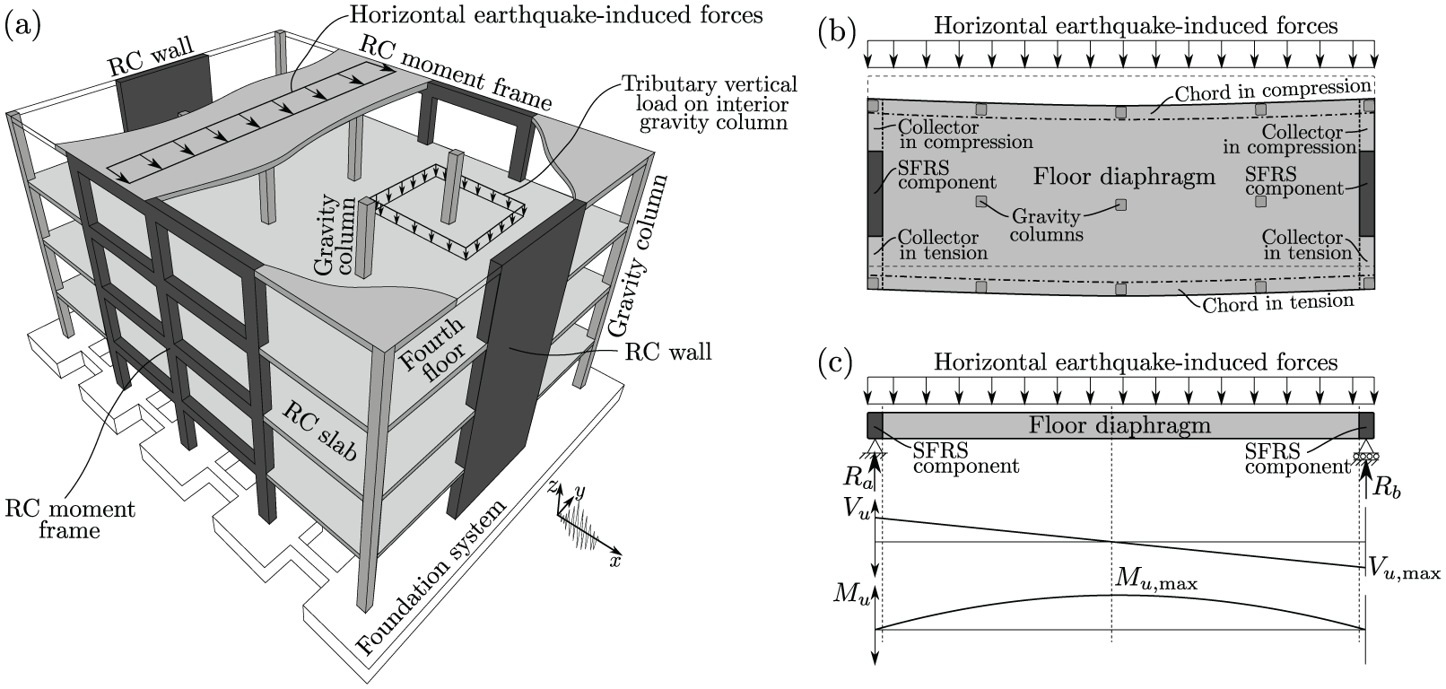
(a) Schematic representation of an earthquake-resistant building. (b) Plan view of the floor diaphragm and its components. (c) Internal shear (
The gravity and vertical earthquake-induced accelerations on the floors produce vertical loads acting out of the plane of the floors. These loads are primarily transferred from the floors to the gravity columns through gravity beams or directly through out-of-plane internal shear forces in the floors. Each gravity column cumulatively takes the vertical loads corresponding to its tributary area at each floor to the foundations, mainly through axial internal forces. Figure 1a shows the fourth-floor tributary vertical load on one of the interior gravity columns.
The horizontal earthquake-induced accelerations on the floors generate horizontal forces proportional to the seismic mass distributed on the floors. These forces are primarily transferred from the floors to the vertical elements of the SFRS through in-plane internal shear, moment, and collector forces in the floors. The vertical elements of the SFRS take these forces to the foundation through a combination of axial, shear, and moment internal forces.
In addition to transferring vertical and horizontal forces, floors provide the in-plane horizontal kinematic compatibility between the vertical structural elements of the gravity load-resisting system and the vertical elements of the SFRS connected to the same floor. Because of this function, they are known as floor diaphragms. Note that the floor diaphragms form part of both the gravity load-resisting system and SFRS.
Floor diaphragms
Floor diaphragms in their plan view can be conceptually represented by deep beams loaded by distributed horizontal earthquake-induced forces and supported by the laterally stiff structural components of the SFRS, as shown in Figure 1b and c. This beam representation is intended solely to illustrate the internal force mechanisms in floor diaphragms, not as a modeling approach. The internal shear forces (
Estimates of the horizontal earthquake-induced forces at each floor level of buildings are required for designing the floor diaphragms, including their chords and collectors. These horizontal earthquake-induced forces are proportional to the horizontal earthquake-induced accelerations at each floor level of buildings (Newton’s second law).
Past seismic performance of floor diaphragms
Underestimating the horizontal earthquake-induced forces on floor diaphragms could be catastrophic. Loss of the ability of floor diaphragms to transfer forces to the vertical elements of the SFRS could lead to local or total collapse of buildings. Floor diaphragm collapses were observed after the Northridge earthquake due to the loss of connections between floor diaphragms and the vertical elements of precast concrete buildings and tilt-up-wall buildings (Earthquake Spectra, 1996; Fleischman and Farrow, 2001; Iverson and Hawkins, 1994). These types of building systems are generally more vulnerable to horizontal earthquake-induced forces because of the use of non-monolithic connections between the floor diaphragms and the vertical elements of the SFRS. After the 2010–2011 Christchurch earthquakes, excessive damage and collapse of floor diaphragms were attributed to inadequate integrity of the load path, underestimation of horizontal earthquake-induced forces, and poorly understood interactions between floor diaphragms and walls, moment frames, and supporting beams (Gonzalez et al., 2017; Kam et al., 2011; Scarry, 2014). The complex interactions between floor diaphragms and other structural elements result in unpredictable seismic responses, which often lead to unexpected structural damage (Bull, 2004; Henry et al., 2017; Kam et al., 2011; Wallace et al., 2012).
Numerical earthquake simulations of buildings have shown that horizontal earthquake-induced forces on floor diaphragms can greatly exceed their design forces (Rodriguez et al., 2002). These excessive forces can lead to inelastic and potentially non-ductile responses of floor diaphragms (Fleischman et al., 2002; Fleischman and Farrow, 2001). The contribution of the second- and higher-mode responses to the total response of buildings (termed higher-mode effects) can cause excessive floor total accelerations and forces (Chopra, 2007; Sewell et al., 1986). For instance, it has been shown that high floor accelerations due to the higher-mode effects can be expected in buildings with an SFRS that concentrates the inelastic response in a flexural inelastic mechanism at the base, such as buildings with flexure-dominant RC structural walls (Chopra, 2007; Fleischman et al., 2002; López and Cruz, 1996; Panagiotou and Restrepo, 2009; Priestley and Amaris, 2002; Tsampras et al., 2016; Wiebe and Christopoulos, 2009).
Design provisions for floor diaphragms
ASCE/SEI 7-22 Section 12.10.1
ASCE/SEI 7-22 Sections 12.10.1 and 12.10.2 (ASCE/SEI 7-22, 2021) describe a method for estimating the in-plane horizontal earthquake-induced forces that can be used to design floor diaphragms, including their chords and collectors. Section 12.10.1 provides estimates of the horizontal earthquake-induced forces based on the forces used to design the vertical elements of the SFRS. Section 12.10.2 indicates that collectors, and their connections, of buildings assigned to the Seismic Design Categories (SDC) C through F shall be designed for load combinations considering the overstrength of the vertical elements of the SFRS.
Design equations. ASCE/SEI 7-22 Section 12.10.1 indicates that a floor diaphragm shall be designed for both shear and bending stresses resulting from the horizontal earthquake-induced forces estimated as:
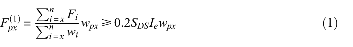
where
Higher-mode response considerations. Although ASCE/SEI 7-22 Commentary C12.8.3 indicates that
The upper limit of
ASCE/SEI 7-22 Section 12.10.3
The alternative design provisions for floor diaphragms per ASCE/SEI 7-22 Section 12.10.3 account for the higher-mode effects and provide estimates of the horizontal earthquake-induced forces, including their chords and collectors. These alternative design provisions are mandatory for precast concrete floor diaphragms in buildings assigned to SDC C through F.
Design equations. The in-plane horizontal earthquake-induced design forces for floor diaphragms, including chords, collectors, and their connections to the vertical elements of the SFRS, are estimated as:
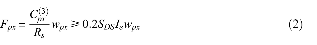
where
where
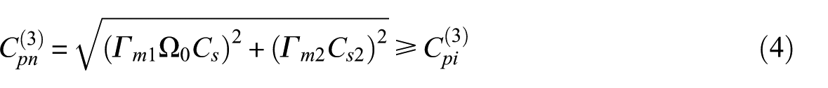
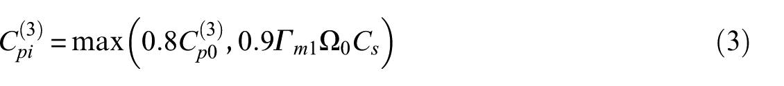
where
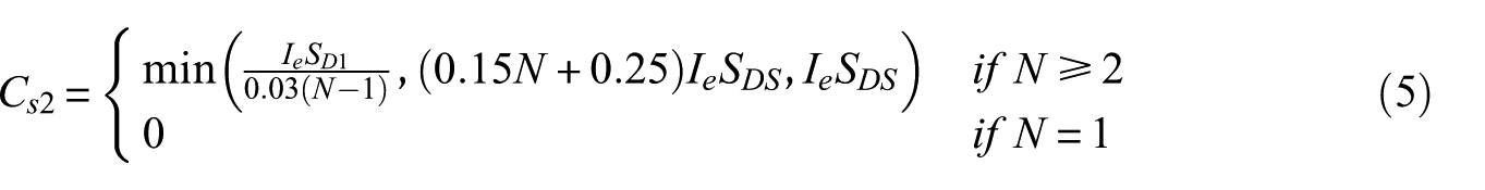
is the higher-mode seismic response coefficient, which depends on the design,
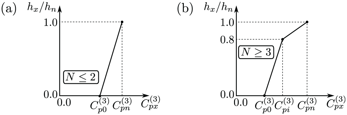
Distribution of
Mayorga and Tsampras (2022) conducted a simple sensitivity analysis to observe the effects of varying
Higher-mode response considerations. ASCE/SEI 7-22 Section 12.10.3.2 neglects the higher-mode effects on
Figure 3 presents
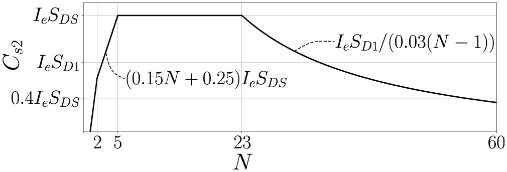
Higher-mode seismic response coefficient in terms of the number of stories.
Remarks
The design equations per ASCE/SEI 7-22 Section 12.10.1 do not consider the higher-mode effects on the magnitude of the floor diaphragm design forces, whereas those per Section 12.10.3 explicitly consider these effects. Thus, the design forces per Section 12.10.3 are expected to provide more accurate estimates of the horizontal earthquake-induced forces than those per Section 12.10.1. However, the alternative design provisions per Section 12.10.3 were developed based on the analysis of limited experimental data from shaking table tests (Chen et al., 2016; Panagiotou et al., 2011) and numerical earthquake simulations (Choi et al., 2008; Fleischman et al., 2013). Therefore, the design provisions for floor diaphragms need to be validated using more extensive data sets, such as the acceleration data and metadata from instrumented buildings subjected to earthquake ground motions.
Scope of study
This article assesses the seismic design provisions for floor diaphragms per ASCE/SEI 7-22 Section 12.10.1 and Section 12.10.3 using strong-motion acceleration data from instrumented buildings (building stations) monitored by the California Strong Motion Instrumentation Program (CSMIP). The building stations comprise multiple stories and SFRS types.
The spectral response factors at the second- and third-mode periods are compared with those at the first-mode period of the building stations to assess the higher-mode effects on the floor acceleration responses. These factors are defined as the ratio between the spectral response acceleration at a given floor and that at the ground, both evaluated at the same modal period. The periods of the first, second, and third translational modes are estimated from the measured strong-motion data using simplified and analytical expressions provided in the literature. The comparison is used to assess how the higher-mode effects are considered in the design provisions.
The design acceleration coefficients are compared with the peak floor accelerations first computed at the center of rigidity of each instrumented floor and then linearly interpolated to the remaining floors. The center of rigidity location is estimated from the measured strong-motion data using a method described in the literature. Additional acceleration coefficients are introduced as a modified version of the design acceleration coefficients to account for (1) the intensity of the measured ground motions and (2) the level of inelastic response of the building stations induced by the measured ground motions. For these reasons, the modified acceleration coefficients are termed design-based intensity-dependent acceleration coefficients. Two metrics are defined to compare the magnitude and floor-to-ground factor of the design-based intensity-dependent acceleration coefficients with those of the peak floor accelerations over the height of the building stations.
The authors acknowledge that Fourier transform-based methods can be used to assess the higher-mode effects. However, this study explores a spectral response-based method that employs concepts widely used in seismic design of buildings. In addition, this article does not cover the assessment of the transfer forces resisted by the portion of the floor diaphragms between vertical elements of the SFRS, nor the horizontal distribution of the horizontal earthquake-induced forces through the floor diaphragms.
Building stations
The Center for Engineering Strong Motion Data (CESMD) provides raw and processed strong-motion data, along with metadata containing information on measurement stations and measured seismic events, for earthquake engineering applications. The strong-motion data available on the CESMD website are collected at stations in seismic monitoring networks across the United States and worldwide, including the network monitored by the CSMIP. The criteria for the selection of the building stations considered in this study are the following: (1) location of site, (2) seismic risk category, (3) type of SFRS, (4) construction date, (5) number of stories, (6) number of measured ground motions, (7) intensity of measured ground motions, (8) number of measurement channels, (9) spatial distribution of channels, and (10) availability of analyzed data in the literature.
Set of selected building stations
A set of 69 instrumented building stations within the California Geological Survey Network (CE) monitored by the CSMIP was selected. The selected building stations have been subjected to ground motions that induced maximum measured peak channel accelerations of at least
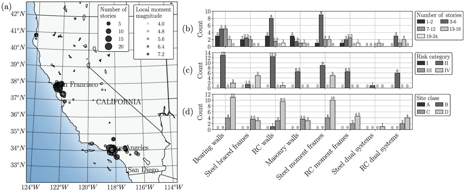
Sixty-nine studied building stations. (a) Geographic location, number of stories, and local moment magnitudes of the ground motions to which the building stations have been subjected. (b) Number of stories, (c) risk category, and (d) site class, each in terms of the SFRS. Half-counting was used for building stations with different SFRS in the two orthogonal directions.
The SFRS for each orthogonal direction of the selected building stations is defined based on the information documented on each building station CESMD website, taking into account the building design date. The SFRS types considered are: bearing walls, steel-braced frames, RC walls, masonry walls, steel moment frames, RC moment frames, steel dual systems, and RC dual systems. The dual systems are SFRS composed of a combination of walls or braced frames and moment frames, where the moment frames can resist at least 25% of the prescribed seismic forces. Figure 4b to d shows the number of stories, risk category, and site class of the building stations by SFRS. The most common SFRS among the selected building stations are bearing walls, RC walls, and steel moment frames, while the least common are steel dual systems, represented by only one building station. The selected building stations have up to 24 stories, fall into the risk categories II or IV, and are located on sites classified as B, C, or D.
Building stations with seismic isolation, stiffness-soft story irregularities, or SFRS not included in ASCE/SEI 7-22 Table 12.2-1 are not considered in the analysis due to their potentially unique distributions of peak floor accelerations over the height (
Framework for analysis of measured strong-motion data and metadata
A workflow for importing, processing, plotting, and utilizing the measured strong-motion data and metadata has been developed using the open-source programming language Python (Mayorga and Tsampras, 2025; Van Rossum and Drake, 2009). The workflow consists of 17 steps. The results from each step are stored in the expanded database as additional metadata. Measured and design-based quantities are introduced and defined progressively within the relevant steps, with design-based quantities explicitly referenced to ASCE/SEI 7-22, where applicable. Each step in the workflow is summarized as follows (see Appendix 2 for a detailed workflow diagram).
Step 1 through Step 5 import, process, and plot the strong-motion data and metadata downloaded from the CESMD website for a selected building station. Additional metadata—such as information from drawings and other sources available for the building station, site, and measured seismic events—are appended to the CESMD metadata.
Step 6 estimates the location of the center of rigidity
Step 8 computes the
Step 11 computes and plots the design spectral response accelerations
Step 14 estimates the seismic performance factors
Step 15 computes the floor diaphragm design-based intensity-dependent acceleration coefficients
Design-based intensity-dependent acceleration coefficients
The design acceleration coefficients
Seismic performance factors at measured ground motion intensity
The seismic performance factors
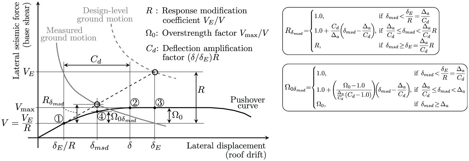
Schematic representation of idealized lateral seismic force versus lateral displacement responses of an earthquake-resistant building. Definition of the seismic performance factors
It is assumed that (1) the deformation of the building is dominated by the first-mode translational response and (2) the roof drift
Modification approaches
The design-based intensity-dependent acceleration coefficients are computed as
Scaling factor
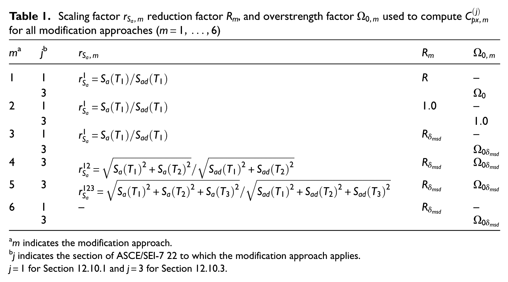
m indicates the modification approach.
j indicates the section of ASCE/SEI-7 22 to which the modification approach applies.
The first two modification approaches represent the extreme cases in terms of the level of inelastic response of the building stations. The third, fourth, and fifth modification approaches include the level of inelastic response estimated based on the peak roof drift response and use the spectral response accelerations of the ground motions at the first three translational mode periods to compute scaling factors. The sixth modification approach directly incorporates the spectral response accelerations at the first three translational mode periods into the design equations. As a result,
Comparison metrics for assessment of design provisions
The metrics used to compare
The ratios
The relative errors
Ratio metrics greater than 1.0 indicate underestimation of the measured responses, while those less than 1.0 indicate overestimation. Error metrics closer to zero indicate a more accurate estimation of the measured responses. Both metrics are selected due to their relative (dimensionless) nature, enabling consistent comparisons across all studied cases.
Assessment of design provisions
This section assesses the floor diaphragm seismic design provisions as per ASCE/SEI 7-22 Section 12.10.1 and Section 12.10.3 using the strong-motion earthquake responses measured by the 69 selected building stations located in California. Emphasis is given to how the design provisions incorporate the higher-mode effects in their formulations. Initially, the floor spectral response accelerations
Note that the quantities presented in this section can be grouped as follows: (1) those computed directly from measured strong-motion data:
Example building station
The example building station is a 17-story residential building located in Los Angeles. Its SFRS consists of bearing walls in the two orthogonal directions, its site class is C/D (sedimentary site geology), and its seismic design category is D. This building station was selected because it has been subjected to two ground motions with distinct
Spectral response accelerations
Figure 6a shows the floor spectral response accelerations
(a) Spectral response accelerations and (b) spectral response factors at
Peak floor accelerations
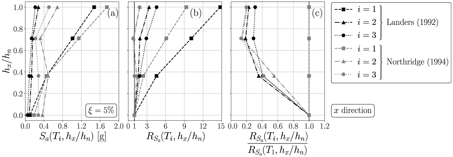
Figure 7a to c presents the design and measured spectral response accelerations at the ground, peak floor accelerations, and peak floor acceleration factors, respectively, in the
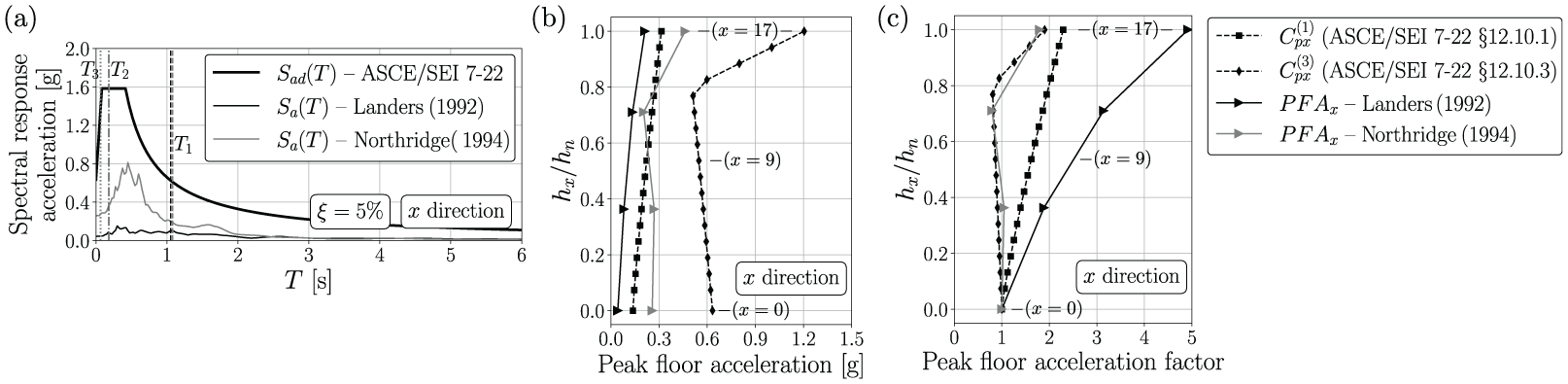
Design and measured (a) spectral response accelerations at the ground, (b) peak floor accelerations, and (c) peak floor acceleration factors of the CE24601 Building Station subjected to the Landers (1992) and Northridge (1994) seismic events.
Figure 7b shows that
Figure 7c shows that
Figure 8a and b shows the design-based intensity-dependent acceleration coefficients (
Figure 8c and d presents the design-based intensity-dependent and measured peak floor acceleration factors (floor-to-ground factors). The factors
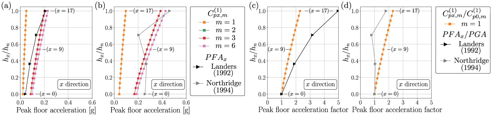
Design-based intensity-dependent and measured peak floor accelerations of the CE24601 Building Station subjected to the (a) Landers (1992) and (b) Northridge (1994) seismic events. Design-based intensity-dependent and measured peak floor acceleration factors for the (c) Landers (1992) and (d) Northridge (1994) seismic events.
Figure 9a and b shows the design-based intensity-dependent acceleration coefficients (
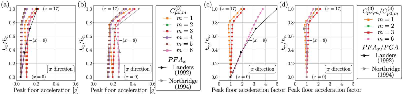
Design-based intensity-dependent and measured peak floor accelerations of the CE24601 Building Station subjected to the (a) Landers (1992) and (b) Northridge (1994) seismic events. Design-based intensity-dependent and measured peak floor acceleration factors for the (c) Landers (1992) and (d) Northridge (1994) seismic events.
Figure 9c and d presents the design-based intensity-dependent and measured peak floor acceleration factors (floor-to-ground factors). For both seismic events,
It is observed that
All selected building stations
The floor spectral accelerations and peak floor accelerations computed from the strong-motion data measured by the selected building stations are analyzed statistically. The same quantities and comparison metrics used in the assessment of the design provisions for the example building station are extended to multiple building stations with different SFRS. Building stations with steel dual systems are excluded from the analysis, as only one data point exists for this SFRS among the selected stations.
Spectral response accelerations
Figure 10 presents the mean values of the ratios
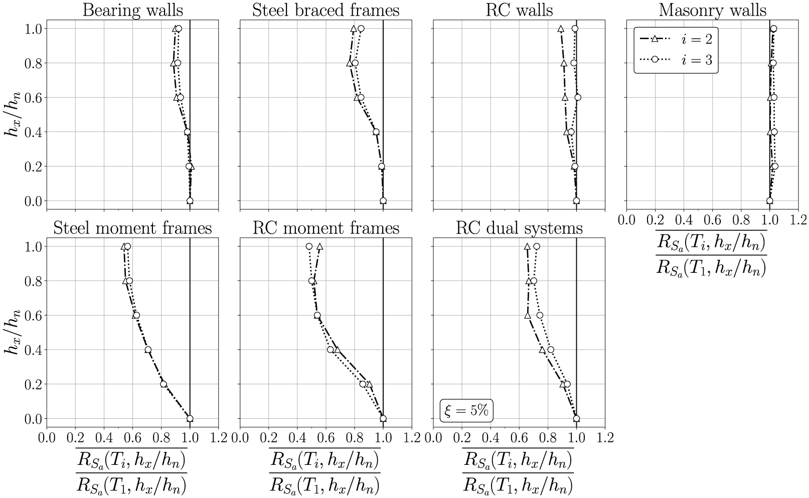
Mean values of the ratio of the spectral response factors at
On average,
Figure 11a presents
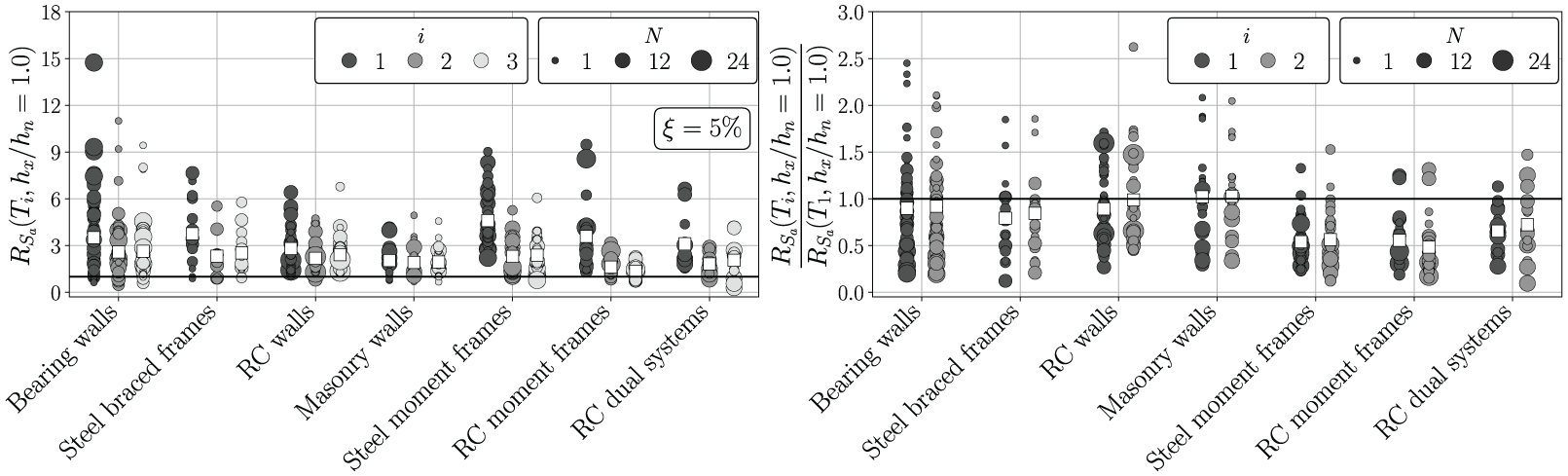
(a) Spectral response factors at
Table 2 presents the mean values and coefficients of variation of the ratios
Mean values and coefficients of variation of the spectral response factors at
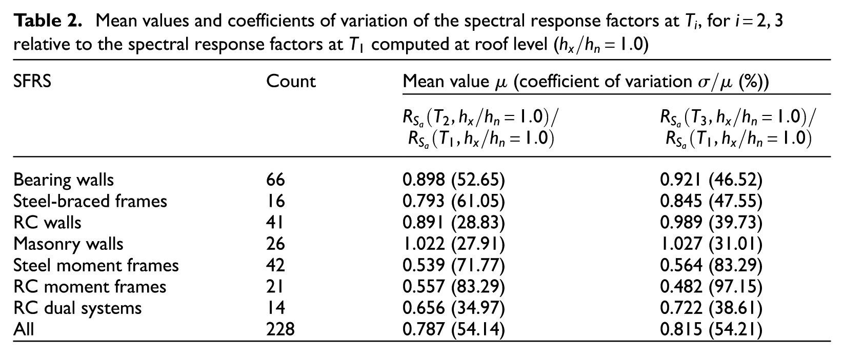
The average of the mean values of the ratios
Peak floor accelerations
Figure 12 shows the values of
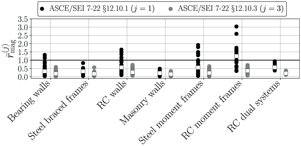
Table 3 presents the mean values and coefficients of variation of
Mean values and coefficients of variation of
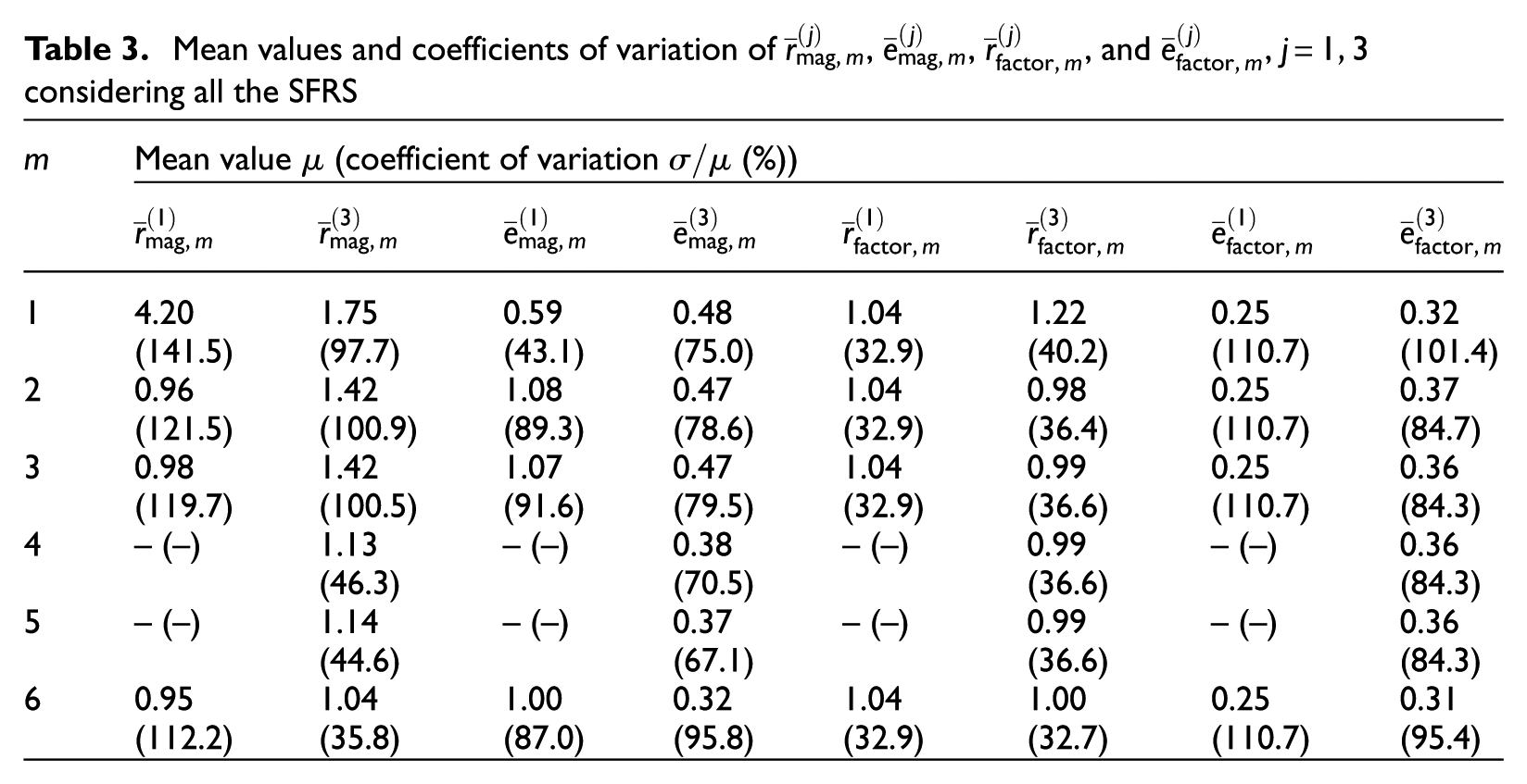
Table 3 shows that, for
Table 3 indicates that the mean values of
Figure 13a and b shows the comparison metrics
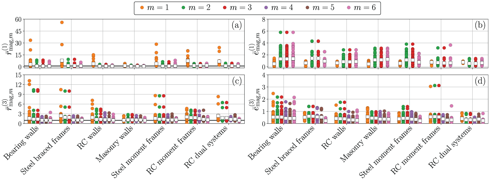
(a)
Table 4 presents the mean values and coefficients of variation of
Mean values and coefficients of variation of the
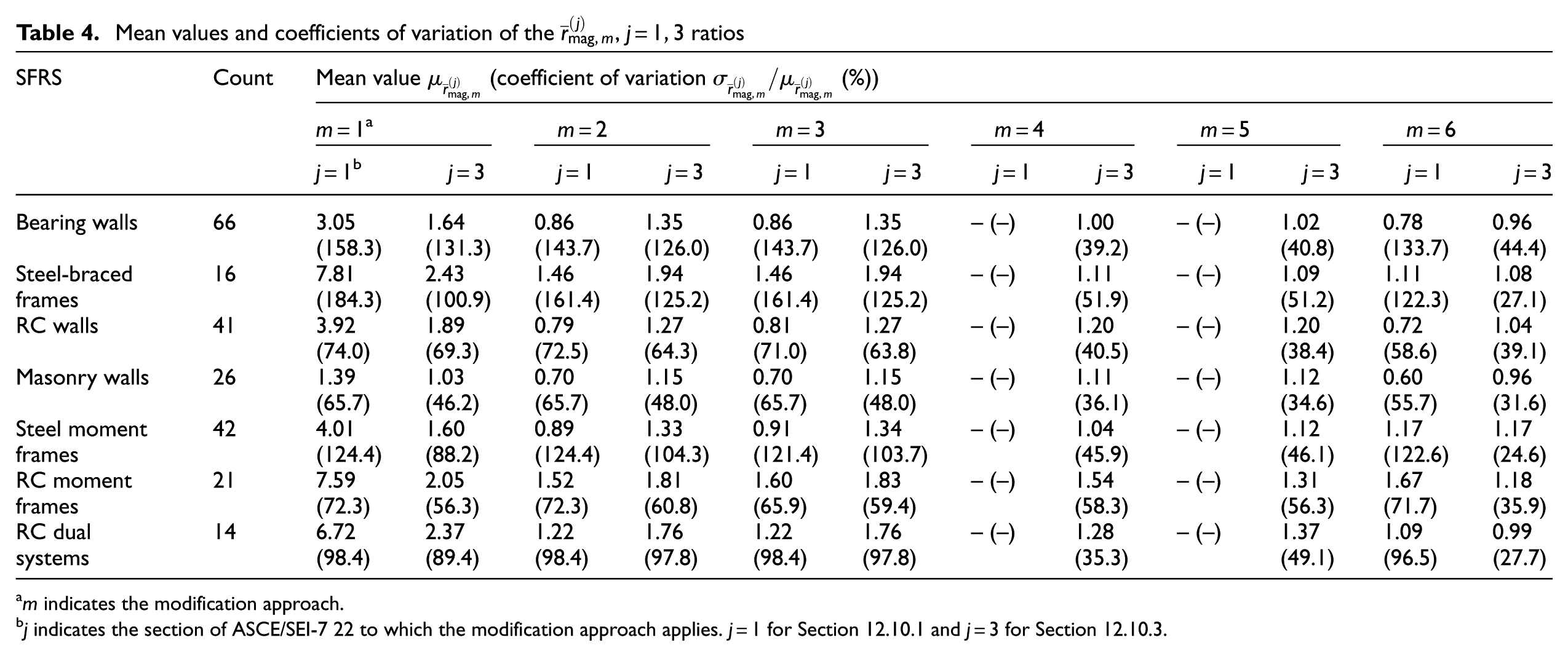
m indicates the modification approach.
Mean values and coefficients of variation of the
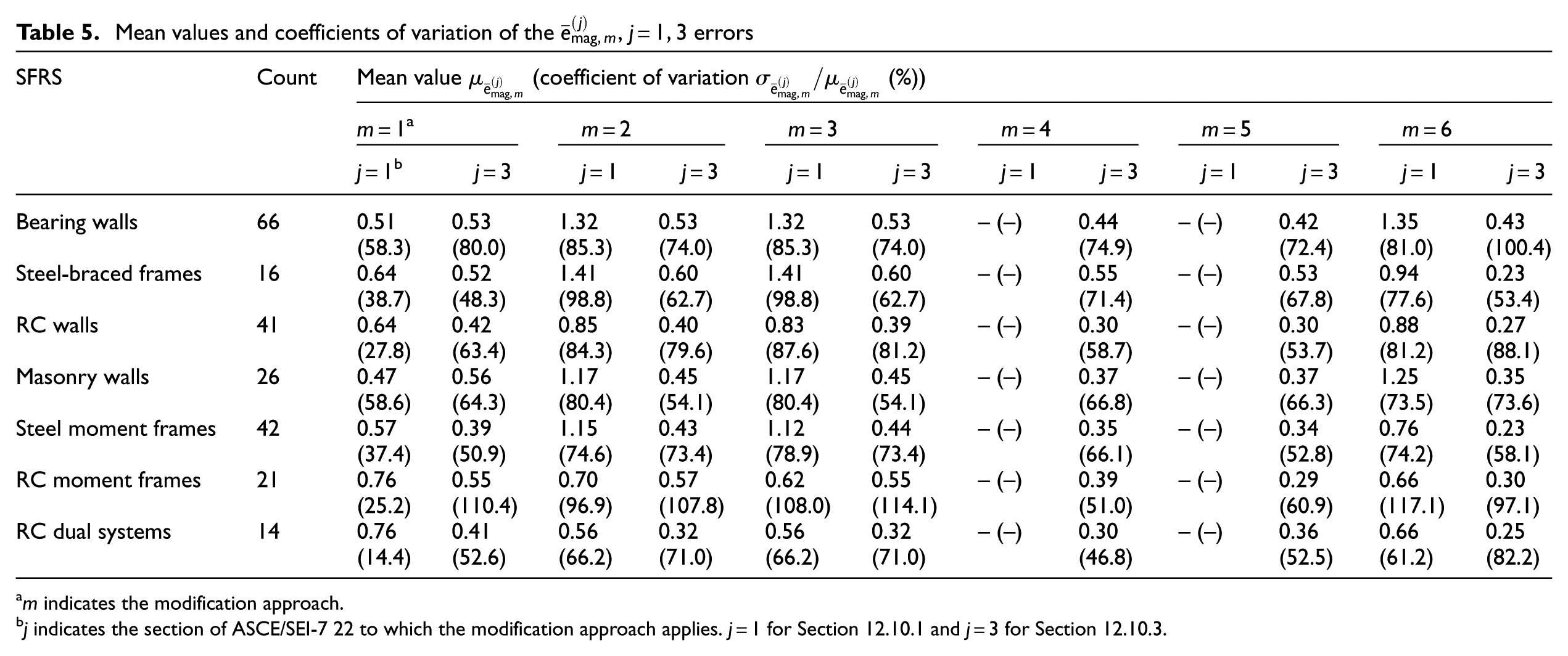
m indicates the modification approach.
Figure 13a and c illustrates considerable dispersion in
Effects of level of nonlinear response. Table 4 shows that, except for masonry walls, the mean values of
Effect of including
Effects of
Effects of SFRS. The seven SFRS are compared for
Conclusion
This article assessed the seismic design provisions for floor diaphragms per ASCE/SEI 7-22 Section 12.10.1 and Section 12.10.3, focusing on how these provisions consider the higher-mode effects on the horizontal floor accelerations of earthquake-resistant buildings. While the design provisions were developed based on limited experimental tests and numerical earthquake simulations, this study assesses these provisions using strong-motion data from a diverse set of instrumented buildings in California. In addition, the framework developed for processing and analyzing the strong-motion data provides a practical tool that can facilitate the use of the CSMIP data set in other research and engineering applications. Based on the results of this study, the following conclusions can be drawn:
The mean values of the ratio of the spectral response factors at the second- and third-mode periods to those at the first-mode period, computed at roof level, are lower for steel moment frames and RC moment frames than for wall systems. This result is consistent with the formulation of the design equations per ASCE/SEI 7-22 Section 12.10.3. However, the dispersion of these results is considerable, especially for steel moment frames and RC moment frames.
The mean values of the ratio of the spectral response factors at the second- and third-mode periods to those at the first-mode period, computed at roof level, are lower for steel braced frames than for wall systems. However, ASCE/SEI 7-22 Section 12.10.3 assigns the same mode shape factor to these SFRS.
The design-based intensity-dependent acceleration coefficients based on ASCE/SEI 7-22 Section 12.10.1 can significantly underestimate the peak floor accelerations if the spectral response accelerations at the ground evaluated at the second- and third-mode periods are considerably larger compared to those evaluated at the first-mode period.
The design-based intensity-dependent acceleration coefficients based on ASCE/SEI 7-22 Section 12.10.3 can capture the increase of peak floor accelerations caused by either the higher-mode spectral response accelerations at the ground or by the higher-mode response contribution characteristic of the dynamic properties of the building stations.
Data from instrumented buildings subjected to design-level ground motions and multi-directional earthquake simulation tests are needed to fully validate floor diaphragm design provisions. Increasing the number of instrumented floors of building stations based on the number of stories will improve the assessment of higher-mode effects, particularly at mid-height levels of buildings.
The authors recommend using the alternative design provisions per ASCE/SEI 7-22 Section 12.10.3 over Section 12.10.1 to estimate the seismic-induced horizontal inertial forces for floor diaphragm design. However, the definition of the mode shape factor given in Section 12.10.3 needs to be revised to clarify the distinction between the effects of linear-elastic dynamics and the distribution of nonlinearity over the height of the building on the peak floor acceleration responses of different SFRS.
Footnotes
Appendix 1
Appendix 2
Acknowledgements
The authors thank Dr. Daniel Swensen for coordinating the project activities, and Dr. Lisa Schleicher, Dr. Mehmet Çelebi, and Dr. Erdal Şafak for their assistance in implementing the method to estimate the location of the center of rigidity of the building stations from measured data. The inputs from the members of the Buildings and Data Utilization Strong Motion Instrumentation Advisory Subcommittees are also gratefully acknowledged.
Authors’ note
Any opinions, findings, and conclusions expressed in this paper are those of the authors and do not necessarily reflect the views of others acknowledged here.
Funding
The authors disclosed receipt of the following financial support for the research, authorship, and/or publication of this article. This research was supported by the California Strong Motion Instrumentation Program through the project “Validation of Seismic Design Provisions for Diaphragms and Assessment of Higher-Mode Responses on Earthquake-Resistant Buildings,” and by the Chilean National Agency for Research and Development (ANID) through the Foreign Doctoral Scholarship 2020.
Declaration of conflicting interests
The authors declared no potential conflicts of interest with respect to the research, authorship, and/or publication of this article.
Data and resources
The framework developed in this study for processing and utilizing data from the CESMD to assess seismic design provisions for floor diaphragms is publicly available on DesignSafe-CI (Mayorga and Tsampras, 2025). This framework enables the reproducibility of the results of this study and facilitates further research on the topic.