
Abstract
On February 6, 2023, two earthquakes (Mw 7.8 and 7.5) occurred in Turkey. Notably, 10 provinces in Turkey and several others in Syria were subjected to severe ground shaking, resulting in a high number of casualties following the total and partial collapse of many reinforced concrete buildings. Although moderate damages in non-structural elements were identified in the very few steel buildings that existed, negligible structural damage was generally identified during field inspections. The notable exception was a 7-story steel building in Antakya that partially collapsed. The behavior of the building is examined in detail from the design project report and a previous study of real-time monitoring. Nonlinear analyses were carried out under the accelerograms recorded by the closest stations. The investigation aims to enrich the present knowledge of the structural performance of steel structures under extreme seismic demands.
Keywords
Introduction
On February 6, 2023 at 04:17 am local time, an earthquake occurred at a depth of 17.9 km (Mw 7.8) in southeastern Turkey. The epicenter was located at 37.174°N and 37.032°E, near the city of Nurdağı in the province of Gaziantep. A second earthquake triggered by the first one occurred on the Sürgü-Çardak fault (Mw 7.5) with an epicenter located at 38.024°N and 37.203°E, near Ekinözü in the province of Kahramanmaraş. As a result of the earthquakes, at least 66,000 buildings were severely damaged or destroyed in Turkey and Syria, and more than 28,500 buildings suffered partial collapse (Dilsiz et al., 2023).
Lessons learned from the performance of steel frames under intense seismic loads are helpful to the advancement of the ductile frames’ state of the art and practice. FEMA 355e (2000) summarizes the recorded performance of steel buildings prior to the 1994 Northridge earthquake. After that event, around 1032 steel buildings were damaged with different degrees by the 1995 Hyogoken-Nanbu Earthquake (Suzuki et al., 1995). Some eccentrically braced frames developed link fractures, and brace fractures of concentrically braced frames were identified during the Christchurch earthquake series of 2010 and 2011 (Clifton et al., 2011). In addition, during the Puebla earthquake of September 19, 2017, a 3-story regular building structured with steel truss moment-resisting frames experienced extensive non-ductile damage in the columns of the first floor (Tapia-Hernández & García-Carrera, 2020).
The main focus of this investigation is based on a field inspection carried out by the authors 7 weeks after the twin earthquakes. This is complemented by previous studies conducted by the second author on existing buildings, carried out a few years before the seismic sequence. The field studies covered cities and towns in the provinces of Gaziantep, Kahramanmaraş, Adıyaman, Osmaniye, and Hatay, and lasted for 12 days. Although it was difficult to determine the exact number of steel structures that were subjected to the earthquakes, it was observed that most of the structures in the impacted region were moment-resisting reinforced concrete frames, and both confined and unconfined masonry structures (Tapia-Hernández et al., 2024a). Steel frame buildings were extremely rare.
The Turkish Building Earthquake Code (TBEC-2018, 2018) was similar in rigor to other specialized seismic codes (Büyüksaraç et al., 2022). The TBEC comprises 17 chapters and was officially published in the Official Gazette in March 2018, coming into legal effect in January 2019. The code was revised in 1975, 1997, and 2007 before the update.e-Government Gateway (AFAD, 2023) determines the current normative design spectra based on coordinates, ground classification, and site dynamic characteristics. In contrast, the design spectra in codes before 2007 were only defined for four zones, each with a constant peak ground acceleration coefficient (0.4, 0.3, 0.2, and 0.1). When applicable, the design spectra will be included in the following discussion.
The study is divided into five sections. After the “Introduction” section, which describes the scope, motivation, and organization of the study, the “Characteristic of the steel buildings” section provides an overview of the structural systems and cross-sections used in the affected region. The causes of the damage in masonry infill walls and other non-structural elements are analyzed in the “Non-structural components” section. The main discussion is held in the “Antakya building” section, where the structural damage in a 7-story building is described. This section includes a description of the building, details of the construction stage, and the seismic demands recorded in the nearest acceleration stations. Real-time monitoring results were used to calibrate nonlinear analysis to better understand the redistribution of forces and the performance that led to the partial collapse. The conclusions are presented in the “Conclusion” section.
The narrative provides timely insights into seismic design practice and helps to improve the state of the art in steel structures. In the discussion, whenever possible, reference is made to the geographical coordinates of the buildings in question, so that interested readers can observe the pre-earthquake conditions of the buildings.
Characteristic of the steel buildings
Based on post-earthquake inspection in the field, moment-resisting steel frames (MRFs) were the most widely used type of framing. The most common shapes used in columns were wide flange (I-shape) and hollow structural sections (HSS), as shown in Figure 1. The beams were either hot-rolled, welded I-shape, or truss girders composted of angle sections or HSS.
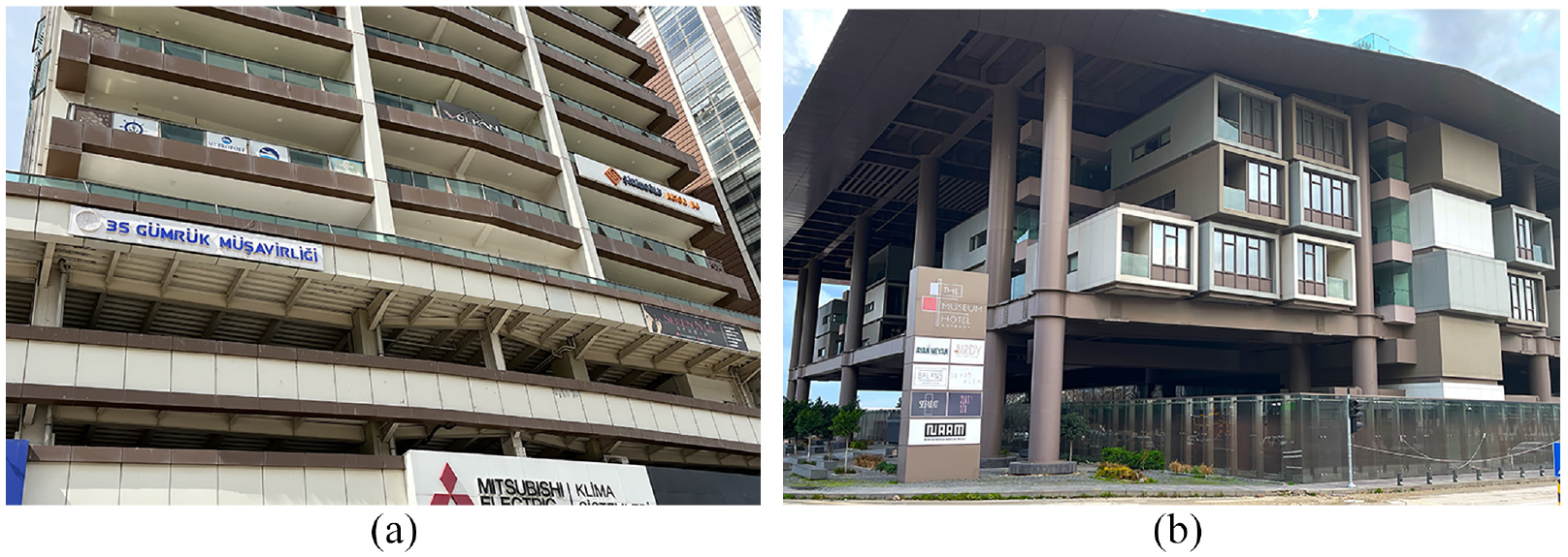
Typical steel structures in the affected region. (a) MRF with box-section columns; Iskenderun, province of Hatay; Facing Southeast (Coord. 36.5846, 36.1760). (b) MRF with circular columns; Antakya, province of Hatay; Facing East (Coord. 36.2113, 36.1748).
Despite the post-earthquake inspection focused the attention on the performance of steel buildings, hundreds of structures were damaged and even collapsed under the seismic sequence. Consequently, it is challenging to accurately determine the inclusion of all steel buildings and dwellings in this study. Therefore, the following discussion in some cases is limited to the detailed inspection, supported by interviews with local citizens and the local engineering community. In general, as far as it was identified, buildings with steel systems reported no or minor structural damage. As discussed in detail in the following sections, only two buildings with partial collapse were identified in the field inspection in the region. As far as could be observed during the inspection, no total or partial collapse could be attributed to the connections in moment frames.
A building used as an automotive agency with a lightweight roof and structured with truss moment frames consisting of box columns and open-web truss girders partially collapsed (Figure 2a). It was located on Atatürk Street in Antakya, province of Hatay (Coord. 36.2352, 36.1696). According to field measurements, the building had a rectangular plan shape approximately 17 × 29 m2. The date of construction of the automotive agency was established after May 2020. All girders were truss girders built up of HSS sections welded directly without intervening steel plates. The automotive agency had large spans for the exhibition area and vehicle maneuvers.
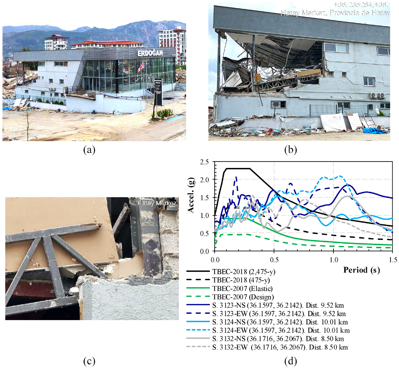
Partial collapse of automotive agency: Merkez, province of Hatay (Coord. 36.2352, 36.1696). (a) General view; Facing North. (b) Lateral façade; Facing Northeast. (c) Detail of the damaged connection. (d) Design and response spectra.
The truss-to-column connections were designed as moment-resisting since the truss girders were welded at the top and bottom chords to the column. Based on the inspection, the low quality of welding seams was identified typical of onsite welding, which did not support the cyclic demands and resulted in cracking (Figure 2b). No damage was found at the welded joints of web of the truss, and no buckling of the compression diagonals was identified. The collapse was caused by a fracture in the chords at the welded connection (Figure 2c). Besides the truss girder collapse, there was a severe cracking in both directions of the masonry infill walls. It is desirable that the masonry walls should be adequately confined and tied to the concrete structure to prevent out-of-plane failure, and they should be competent in withstanding relatively high compression. Figure 2c indicates that the out-of-plane failure of the infill walls occurred without any signs of proper reinforcement after the collapse.
Skilled labor and close supervision are desirable for steel structures that would contribute to reducing the damage related to the construction process. In fact, as demonstrated in previous earthquakes, cases with poor detailing quality have led to partial or complete collapses (e.g. Clifton et al., 2011; FEMA 355e, 2000; Tapia-Hernández & García-Carrera, 2020).
Figure 2d compares the response spectra of the ground motions recorded by the three nearest accelerometric stations to the automotive agency with the current seismic design spectrum (TBEC-2018, 2018). The distance between these stations and the damaged building (which is less than 10 km) is also included to emphasize their proximity. The seismic forces applied represented the design demand for short periods. According to the Turkish Building Earthquake Code (TBEC-2018, 2018), the local ground is classified as ZD (medium-firm to firm layers of sand, gravel, or very solid clay) with a shear velocity expected of 180–360 m/s in the top 30 m. However, for systems with natural frequencies in the 1 s or larger range, the difference is noticeable. The spectra design of TBEC-2007 (2007) was also included to demonstrate the changes in the local seismic code over time for these coordinates. Due to their dynamic characteristics, the automotive agency building should have had a short period (approximately 0.10–0.30 s). As a result, the structure was demanded by a high imposed acceleration than the one defined by the seismic design spectrum (475 years).
Non-structural components
Non-structural components can be vulnerable to earthquake demands, even in moderate seismic events. The financial losses due to non-structural damage might be substantial, often reaching nearly 80% of the total financial investment during medium-level earthquakes (Ding et al., 2024). Masonry infill walls are commonly used as internal partitions and external enclosures in steel frames in seismic regions. Despite they are considered non-structural elements, evidence has shown that infill walls interact with the structural system during an intense earthquake (Tapia-Hernández et al., 2024b; Xie et al., 2020). The masonry walls must be properly confined and tied to the structure to prevent out-of-plane failure.
Generally, in the inspected steel buildings, the masonry walls were not tied into the concrete slab, but in some cases, they were just mortared to the columns. Masonry walls, being more rigid than steel frames, cannot resist the same level of lateral displacement without experiencing tensile cracking. The lack of proper confinement and anchorage led to diagonal shear cracks and collapse in masonry infill walls, which were associated with substantial lateral displacement. This highlights the critical need for proper confinement and anchorage in the design and construction of masonry walls as reported in the following documented cases.
The Steel Tower complex is located on Tayfur Sökmen Street in Iskenderun in the province of Hatay, as shown in Figure 3a (Coord. 36.5850, 36.1752). The complex consists of three 15-story buildings supported by a 4-story tall podium system surrounding it on a mat foundation. Each building has a rectangular plan measuring 45 × 25 m2. The date of construction was established in 2015. They were structured with moment-resisting frames with beams and columns with I-sections (Figure 1a, 3b). The first 4 stories are used as parking, as shown in Figure 3a. It is worth noting that the walls were constructed in a second stage (Figure 3b) that implies that their anchorage was not tied into the concrete slab. The seismic design spectra for the construction date (TBEC-2007, 2007) and the current building code (TBEC-2018, 2018) are shown in Figure 3c. The complex is situated in a region that suffered minimal damage, witho no collapses reported.
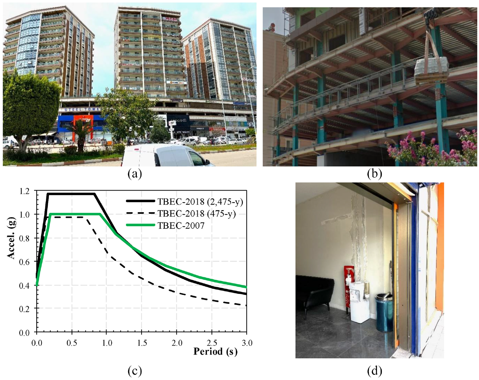
Steel tower: Iskenderun at province of Hatay (Coord. 36.5850, 36.1752). (a) Actual state at the field inspection; Facing Southeast. (b) Detail under the construction stage. (c) Design spectrum.(d) Restoration of the infill walls.
During the technical review conducted in the field, null structural damage was identified in the inspected stories. However, damage was observed in infill walls, particularly in the lower stories, such as dents in the panels or cracks in the sheetrock walls. The lateral stiffness seemed to be insufficient to prevent the non-structural damage, which could be controlled by managing the lateral displacement (Teran-Gilmore et al., 2020). When applicable, steel frames with partial or complete infills reinforced or unreinforced masonry shall be evaluated considering combined stiffness steel frame and infill material (ASCE 41-2023). The residents reported that although the buildings had not yet been unoccupied, finishing works were still in progress. In fact, partially repaired panels were identified during the inspection, as shown in Figure 3d.
A second example of the damage of non-structural systems was a 6-story building used for departments and offices (Figure 4a) constructed as an extension of a main 9-story building. It was located on Atatürk Street in Antakya in the province of Hatay (Coord. 36.2068, 36.1599), which was one of the most damaged regions of the city. In fact, most of the buildings that stood nearby had collapsed during the earthquake sequence (Figure 4b) or were demolished at the time of this writing. According to field measurements, the steel building had a rectangular plan shape approximately 22 × 15 m2.
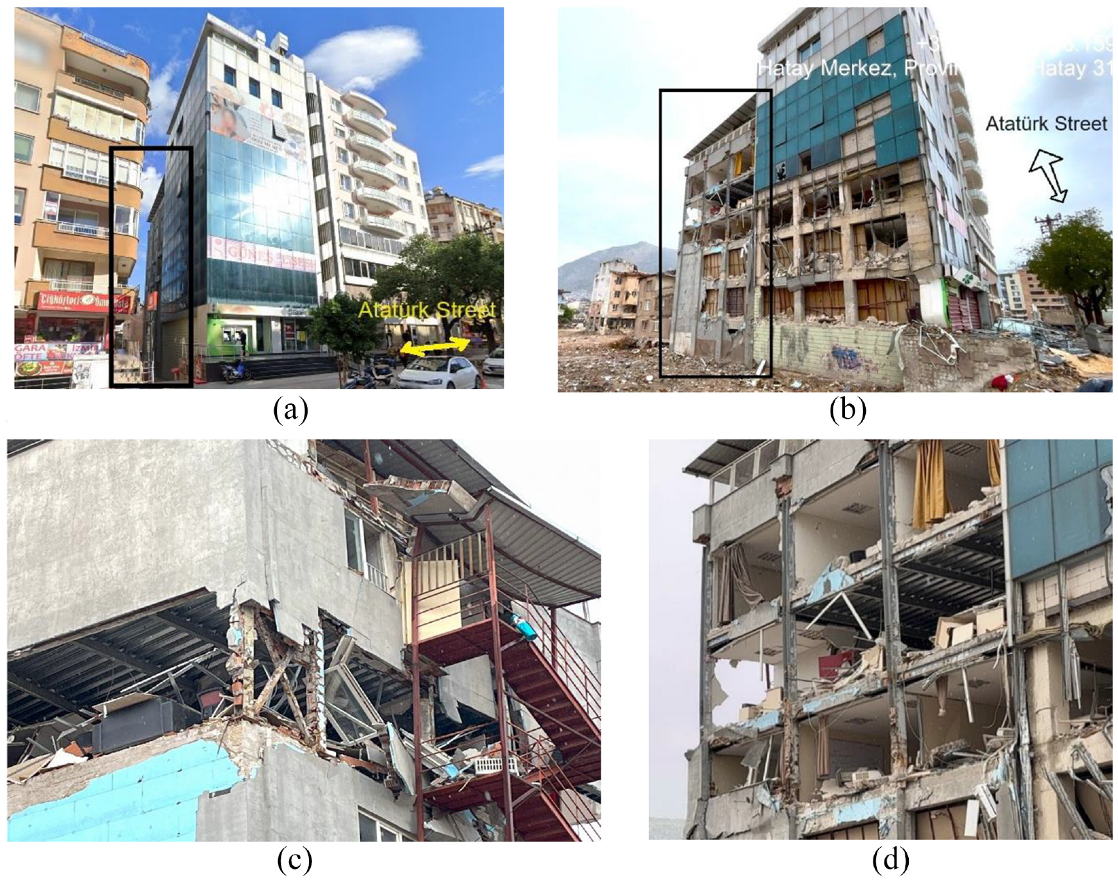
Building of Atatürk Street in Antakya (Coord. 36.2068, 36.1599). (a) Pre-earthquake state; Main façade from Atatürk Street; Facing West. (b) Lateral façade after the earthquake seen from the ground level of a nearby collapsed building; Facing North. (c) Façade from Semih Azmi street; Facing Southeast. (d) Detail of non-structural elements; Lateral façade; Facing North.
The building of Atatürk Street was a moment-resisting concrete frame system at the first three stories. Whereas the upper three stories of the building were MRFs in one direction and concentrically braced steel frames in the short global direction. It seemed that the 6-story building has been added as an extension from the original project in two different stages: first, the stories in reinforced concrete and later, the stories in steel (Figure 4b). It was not possible to inspect the building of Atatürk Street from the interior because it had been evacuated. However, no structural damage was identified in steel and reinforced concrete elements from the outside. Due to the higher lateral stiffness of the concrete frame at the bottom stories, it would be expected to develop more controlled displacements than those developed by the steel structure at the upper stories. However, given the magnitude of imposed demand, severe non-structural damage was identified in all stories.
Bolted joints were used to connect and splice the structural steel elements, which were formed with W-sections. The column splices were located at an appropriate distance from the beam-to-flange connection.
No significant damage was identified at structural elements during the field inspection from the outside. No plastic hinges in beams or columns were identified. There was no evidence of global buckling in braced bays with X configuration (Figure 4c). However, in several bays, the masonry walls were not tied to the steel elements and were only mortared up to the columns. As a result, the brick panels failed due to out-of-plane action, which is a typical damage pattern caused by the lack of confinement and proper anchorage (Figure 4c). In addition, some ceiling panels in a few rooms collapsed, which might be considered as a reference of the level of large drifts experienced during the earthquake (Figure 4d). Although the structural system was undamaged, the building had to be closed because non-structural elements, such as ceiling, glazing, shelves, façade components, and finishes were severely damaged.
During the design stage following modern requirements, the performance level of the entire structural system has to be defined as a suitable combination of the performance levels of its structural and non-structural elements. This is because non-structural components have lower deformation capacity compared to the structural system capacity.
For the purpose of assessing seismic damage, non-structural elements are often categorized as either acceleration-sensitive or displacement-sensitive. Damage to acceleration-sensitive non-structural elements is primarily caused by inertia forces resulting from horizontal and vertical accelerations at various levels in the supporting structure, leading to overturning or excessive sliding/displacement of the elements, such as infill walls not properly tied to the concrete slab (Figure 4c). However, damage to displacement-sensitive non-structural elements is mainly caused by interstory displacements or drifts in the supporting structure, resulting in excessive distortions in the elements; although even the structural system is undamaged. Examples of displacement-sensitive non-structural elements are architectural elements, such as windows, facades elements, and other items that are either not secured or tightly attached into the structure (Figure 4d).
Antakya building (Coord. 36.2191, 36.1587)
One of the most notorious steel buildings affected by the earthquake in Hatay was a complex comprising three mid-rise buildings on 16th Street in Antakya, which were built as steel frames (Coord. 36.2191, 36.1587). Building B partially collapsed, while Buildings A and C had severe non-structural damage (Figures 5a and b).
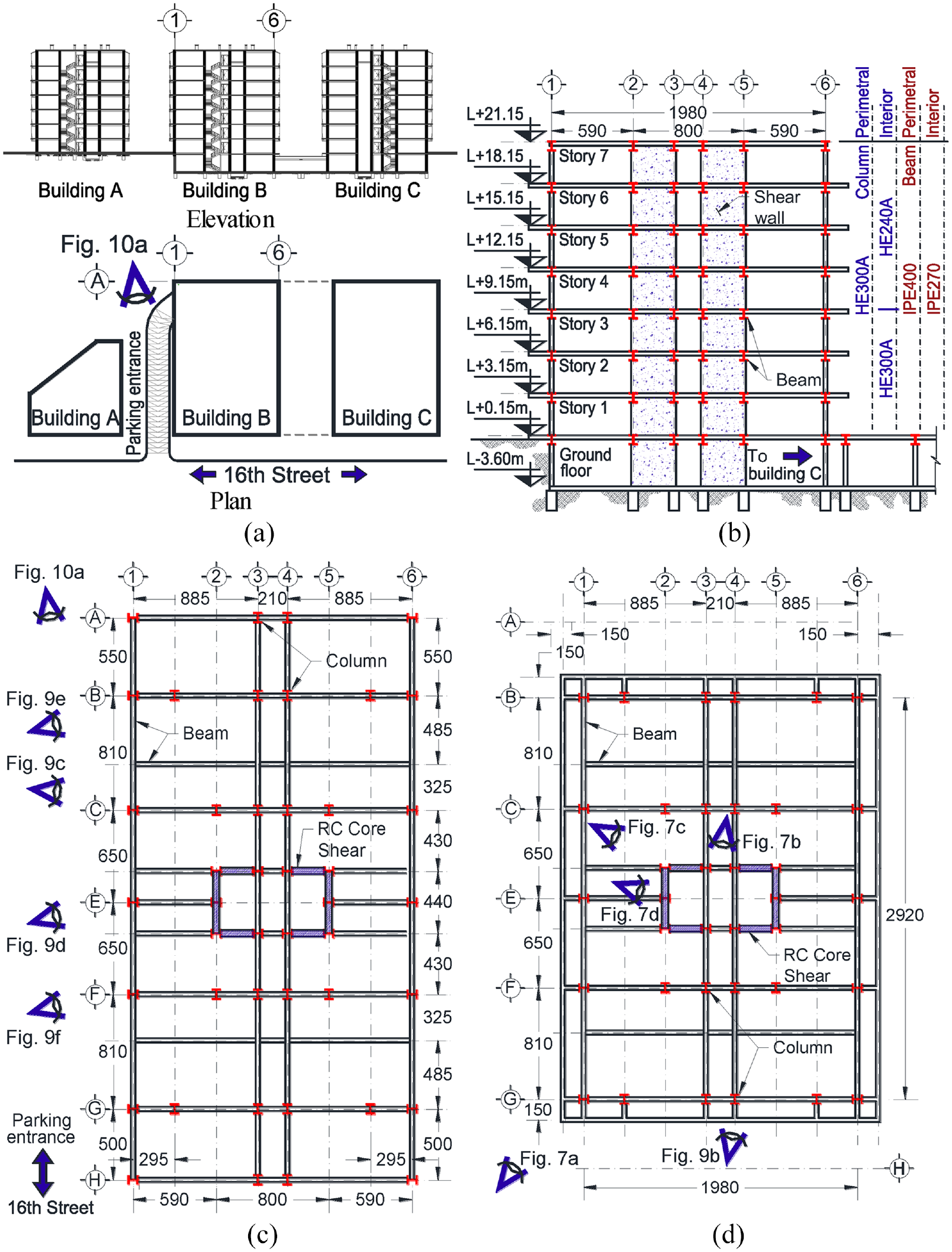
Antakya building characteristics. (a) General view of the complex. (b) Typical elevation of Building B. (c) Ground floor plan of Building B. (d) Typical floor plan of Building B.
The typical floor height was 3.0 m, except for the basement floor, which was used as a parking garage, and had a height of 3.6 m (Figure 5b and c). Buildings B and C shared the same parking area, with the entrance situated between Buildings A and B, as shown in Figure 5a.
The structure consisted of a I-shape columns and beams. The design used European hot-rolled cross-sections, which differ slightly from the similar standard beam sizes, such as AISC. Therefore, the project nomenclature is used in the following discussion to define the cross-sections, and it was included in Figure 5b. Further information on the sizes and dimensions can be found in the corresponding manuals.
The columns had cross-sections HE240A and HE300A with h/t ratios of 27.47 and 30.82, respectively. With this h/t ratio, the webs of the columns were protected against local buckling, according to specialized codes. The limiting value is 59 for steel A572 Grade 50 (e.g. Table D1.1 in AISC 341-2022, 2022). However, the b/2tf ratios for flanges were 10.0 and 10.7; thus, the flanges were slender because the normative width-to-thickness ratio is 9.15 for non-compact sections. This means that the columns could not provide reliable inelastic deformations required for high levels of inelasticity since width-to-thickness ratios were insufficient to prevent local buckling.
The building was a 7-story gravity load structure with reinforced cast in situ concrete core shear walls at the center. Figure 5b shows the cross-sections of the steel members, and Figure 6a provides the structural details of the reinforced concrete core shear. This information is based on the architectural drawings and the construction records available then. The interstory lateral stiffness by the structural system is computed in Figure 6b. Changes in the cross-section of columns and beams throughout the height minimally impact lateral stiffness, as the primary contribution is provided by the shear core, which had the same cross-section throughout the height. A noticeable decrease in lateral stiffness is observed on the parking floor as the interstory height was 3.60 m.
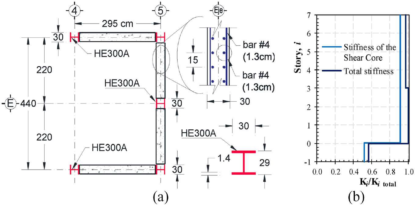
Concrete core shear wall. (a) Structural details (cm). (b) Normalized lateral stiffness.
The building B under the construction process is depicted in Figure 7, dated September 2007. It is worth noting that the infill walls were constructed at a later stage, indicating that the possible confinement was not tied into the concrete slab. Pictures in Figure 7 were placed in the typical plan view of the stories in Figure 5d to facilitate the identification of the discussed structural detail. Column splices were bolted and adequately located at the mid-height, even at the central core of concrete walls (Figure 7b). A composite steel deck with 150-mm thickness was also identified. The steel deck was used in a one-way reinforced slab, with the exception of some cantilever beams and the core shear, according to the pictures on the construction stage (Figure 7).
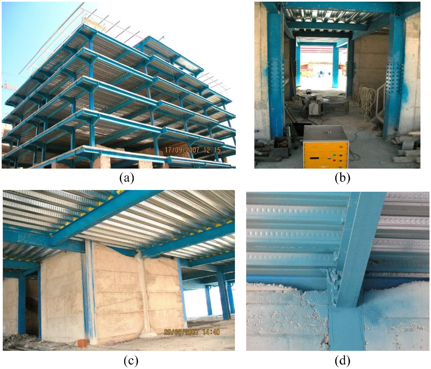
Construction stage of building the Antakya building. (a) Lateral view during construction. Facing Northeast. (b) Central core of concrete walls. (c) Reinforced concrete walls. (d) Incorrect casting of the concrete.
It is worth noting that a deficiency within the casted concrete at the top of the wall was identified (see Figure 7c). This improper casting of the concrete wall prevented an efficient transfer of lateral loads between the central core and steel frames and reflected poor construction supervision (Figure 7d). Limited pictures of the construction process are available. It is not possible to ensure that this cut deficiency occurred in all stories, but it serves as a reference to the quality of the construction process.
The buildings were independent structures next to each other, with 1.5-m long balconies on the main façade (Figure 8a). Cantilever beams were formed using an I-beam section bolted with an end-plate moment connection and reinforced with three plates of varying sections. In contrast, in the internal frames, shear connections were commonly used to connect beams to columns, including the primary beams. These connections transmit only a shear force and zero bending moment, as shown in Figures 7c, 8b, and 8c. Only a few moment-resisting connections were found, mainly in the frames closest to the concrete-reinforced shear core (see Figure 7d). According to some studies (e.g. Liu and Astaneh-Asl, 2004), shear tab connections, when acting compositely with the floor slab, might be capable of providing some lateral resistance in steel frames. This resistance was observed during the 1994 Northridge Earthquake.
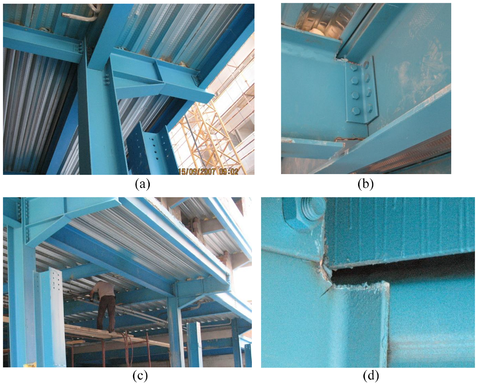
Connections details under the construction stage. (a) Moment connection to the cantilever. (b) Typical shear connection. (c) External frame. (d) Detail of the cutting of elements.
In addition, the cutting of the profiles at the end of the members was not done carefully (Figure 8b). When a torch cut is made in situ, the end members need to be cleaned of any oxides, slag or other protrusions. It seems that this was not performed (Figure 8d). According to the specialized design procedure (e.g. ASCE 7-22, 2022; AWS D18, 2021), notches or gouges, including from thermal cutting and saw cuts, must be removed by grinding. In fact, experimental tests (FEMA 355e, 2000; Tapia-Hernández et al., 2022) concluded that imperfections lead to a critical damage concentration. Limited pictures of the construction process are available. It is not possible to ensure that this cut deficiency occurred in all stories, but it serves as a reference to the quality of the steel elements manufacturing.
Structural damage
Figure 9a shows the state of the buildings after the earthquake. To make it easier to understand the damage description, the position of the pictures on the ground floor plan is shown in the plan view of Figure 5c. It was not possible to inspect the buildings from the interior because the entire complex had been evacuated. However, no structural damage was identified in Buildings A and C from the outside, only critical damage in non-structural elements (Figure 9b).
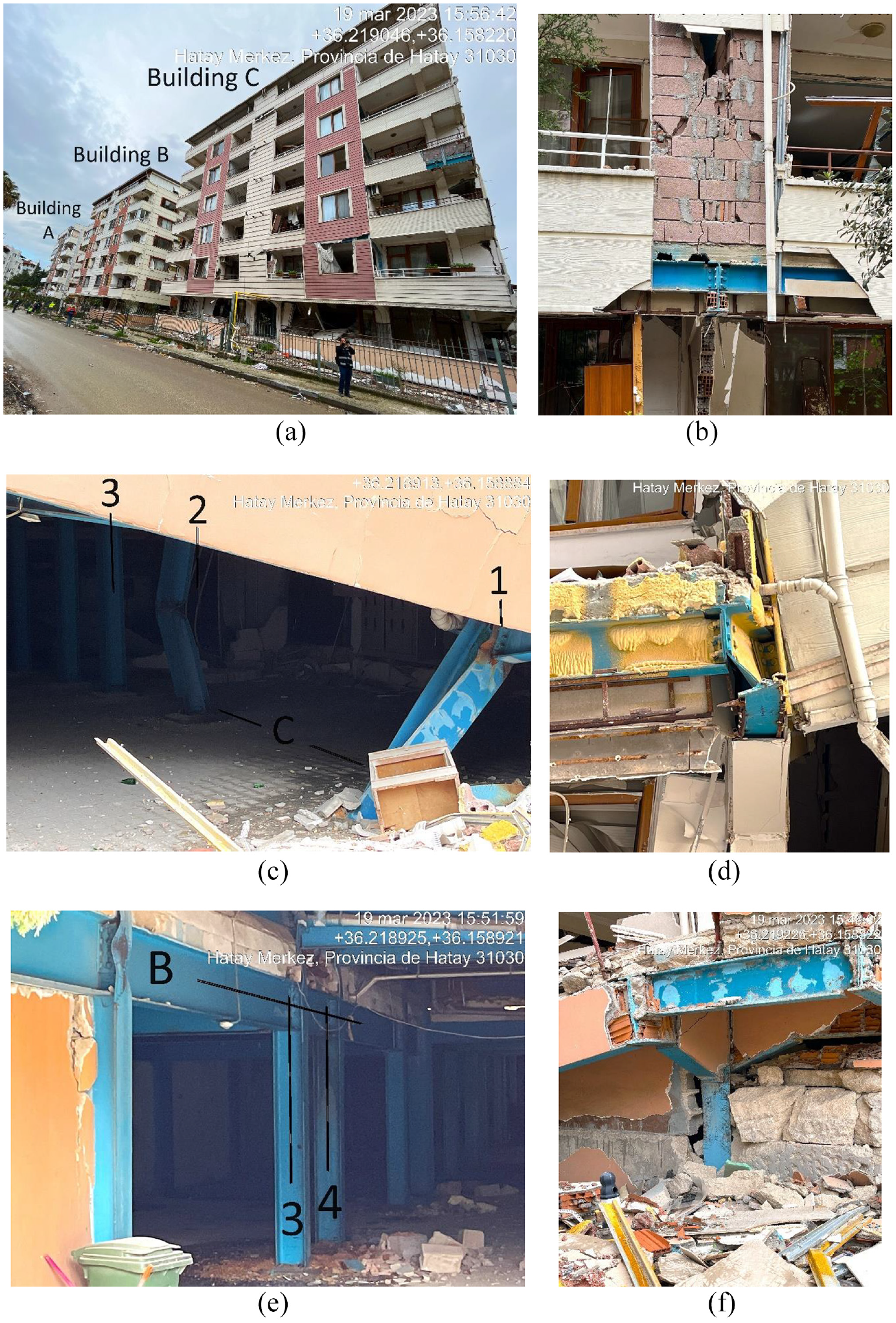
Post-earthquake state of the Antakya building. (a) Main façade of buildings after the earthquake; Facing North. (b) Detail of infill masonry walls. (c) Ground floor; Parking entrance; Frame on axis C; Facing East. (d) Ground floor; Column on axis E-1; Facing East. (e) Ground floor; Parking entrance; Frame on axis B; Facing East. (f) Column on axis F-1.
A partial collapse occurred in the first story of Building B. Specifically, the column at axis C-1 experienced global buckling, as shown in Figure 9c. Probably, the shortening of that column caused the rest of the building to turn, leading to an overall instability and partial collapse. The column at axes C-2 was also buckled at the mid-length to the minor axis of the member toward column C-1. The partial collapse caused a rotation in the structural elements of the columns of axes B and E, as noted in the beams at axis E-1 (Figure 9d). Furthermore, a local buckling of the flange of the column at axes B-1 was also developed (Figure 9e), due to the damage in columns but exacerbated by the slender width-to-thickness ratio as discussed above. Then, a residual deformation was detected at building B, resulting from the concentration of damage at the parking entrance (Figure 9f).
At the time of this writing, it was unknown if further structural damage had occurred to the interior structural elements. However, a significant amount of critical non-structural damage, including the ceiling, glazing, and finishes, has been identified from the outside (Figure 10a).
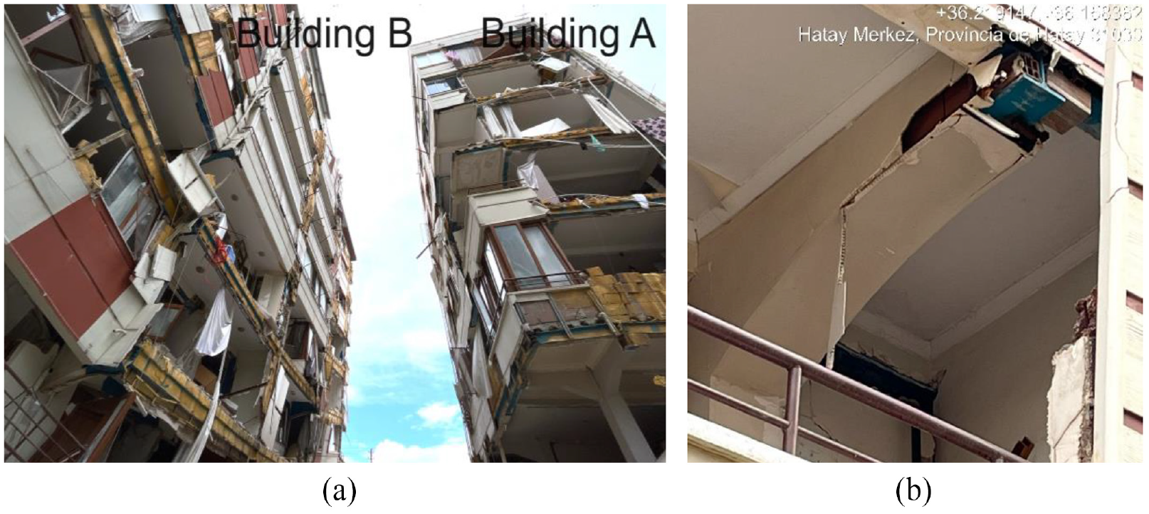
Details of the post-earthquake state of the Antakya building. (a) Building B at left and Building A at right. (b) Damage on cantilever beams.
During a typical design process of steel structures, the contribution of infill walls to the lateral load capacity is generally not considered for resisting seismic demands. However, in practice, these walls act in in-plane shear to carry some of the lateral load. Furthermore, masonry walls are more rigid than steel frames, and thus, they are unable to resist the same level of drift without experiencing tensile cracking, as shown in Figure 10b. This inability to resist drift resulted in damages to masonry infill walls. The post-earthquake state of Buildings A and B is shown here from the parking entrance.
The masonry infill walls were typically built using extruded, multi-cell, hollow clay tiles of 250 × 200 × 80 mm3 with 4- to 6-mm thick walls. Local buckling at the blocks was identified as typical damage in unconfined walls. It was noted that façades were formed using unconfined masonry walls and, in some cases, with lightweight-aerated concrete blocks supported by concrete slabs working as cantilevers. The overhang had a maximum length of 1.5 m, limited by the local code requirements (TBEC-2018). The buildings had infill wall panels made of very brittle extruded masonry. As a result, they could not resist either shear or compression loads associated with the intense demands caused by ground shaking.
Seismic demands
Per the Turkish Building Earthquake Code (TBER-2018), the local ground is classified as ZD, meaning it has medium-firm to firm layers of sand, gravel, or very solid clay. A shear velocity of 180–360 m/s is expected in the top 30 m although the vs30 was closer to 200 m/s than the upper value of that range.
Figure 11 compares the response spectra for the motions recorded during the earthquake in orthogonal horizontal directions with the design spectrum. The nearest stations’ motions, including horizontal and vertical acceleration, velocity, and displacement, were selected. The seismic sequence is considered one of the most hazardous in the wider area, according to probabilistic models (Baltzopoulos et al., 2023). The ground motions have revealed prominent accelerations and also velocity pulses. For instance, the velocity pulse recorded at station 3143 in Hatay Province reached approximately a velocity of 100 cm/s (Lin et al., 2024).
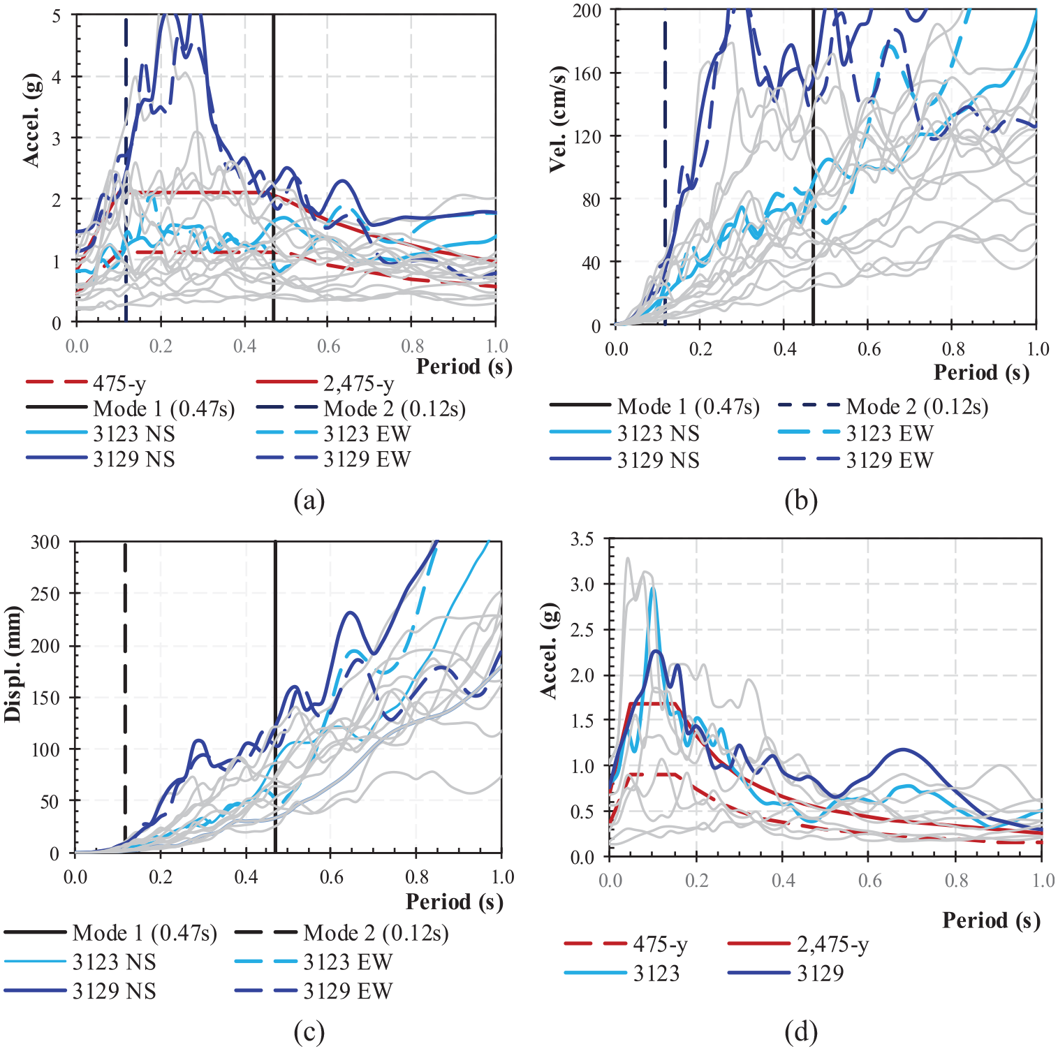
Spectral response recorded at the nearest stations and the design spectra. (a) Horizontal acceleration. (b) Velocity. (c) Displacement. (d) Vertical acceleration.
Although there were no motions recorded at the structure’s location, the magnitude, site-to-source distance, and source mechanisms of the selected records are consistent with those that damaged the buildings during the earthquake (Tapia-Hernández & Tena-Colunga, 2014; Baltzopoulos et al., 2023). The characteristics of the 10 nearest selected records are shown in Table 1. In addition, the design spectra defined by the TBER-2018 (2018) were also included in Figure 11a. Further information about the Turkish Seismic Regulation can be found in the work by Büyüksaraç et al. (2022) and Dilsiz et al. (2023).
Characteristics of the nearest stations
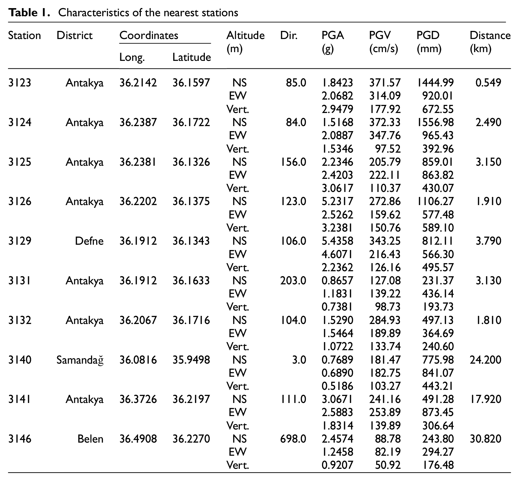
It is worth noting that the strong-motion stations considered in this survey are close enough to the building (less than 30 km) to understand the imposed demands. The closest Station was the 3123, which was only 0.56 km from the complex. Furthermore, prior to the earthquake, real-time monitoring estimated the fundamental period of Building B to be T = 0.47 s. Among the stations, Station 3129, located 3.19 km away, reported the highest demand for this period. The details of the fundamental period are discussed in the following sections. As a result, the demands imposed by Stations 3123 and 3129 were identified in Figure 11. In both cases, the imposed acceleration demands were higher than the design spectra (475 years), and even the records of Station 3129 are equivalent to the 2475-year return period. The results from the other stations in the gray lines in Figure 11 are valuable for establishing a tendency regarding acceleration, velocity, and displacement.
It is worth noting that the vertical acceleration was higher than the one proposed by the spectra design (Figure 11d). The imposed demand may have contributed to the unfavorable behavior. As a matter of fact, damage was identified in non-structural elements that were related to vertical displacements on cantilever beams as discussed above. This damage is certainly related to the clearance between the beam and the drywall and other construction details.
Real-time monitoring
The structural Health Monitoring procedure is a technique used for rapid real-time condition screening of buildings to establish a decision framework for occupants’ safety (Celebi et al., 2014; Murià-Vila et al., 2021). Nowadays, it is widely adopted to monitor the behavior of structures during forced vibration excitations, such as earthquakes, wind, and live loading. For example, a building stock for the Antakya–Maras Region was evaluated using different seismic considerations, including monitoring systems, and can be found in the work by Abrahamczyk et al. (2013).
The building under study was monitored from November 2013 to March 2014 as a part of a previous investigation. A 12-channel monitoring system was installed in the steel building to stream acceleration data in real time and calculate its dynamic properties. However, the equipment was removed long before the Kahramanmaraş earthquake, so the building’s performance during the struck was not recorded. Despite the collected data cannot be used to assess the performance during the earthquake, the available information is valuable for calibrating a numerical model.
During the study, a strong-motion accelerometer CMG-5U was used to capture the dynamic properties of the building. The accelerometer was placed in different locations, including three on the second floor (Ch4, Ch5, and Ch6); three on the fourth floor (Ch7, Ch8, and Ch9); three on the sixth floor (Ch10, Ch11, and Ch12), and three for the free-field station located away from the surrounding buildings (Ch1, Ch2, and Ch3). The accelerometers were placed at the perimeter of each floor to capture the dominant response in both global directions and detect the torsional effect, as shown in Figure 12a. The X-direction was chosen to be parallel to the 16th street, while the Y-direction was perpendicular to the street. Further information about the strong-motion accelerometers and data acquisition system might be found in the work by Genes et al. (2015). Figure 12b shows the location of the building free-field station. CMG-DM24S12AMS data acquisition system was used to obtain the responses (Figure 12c).
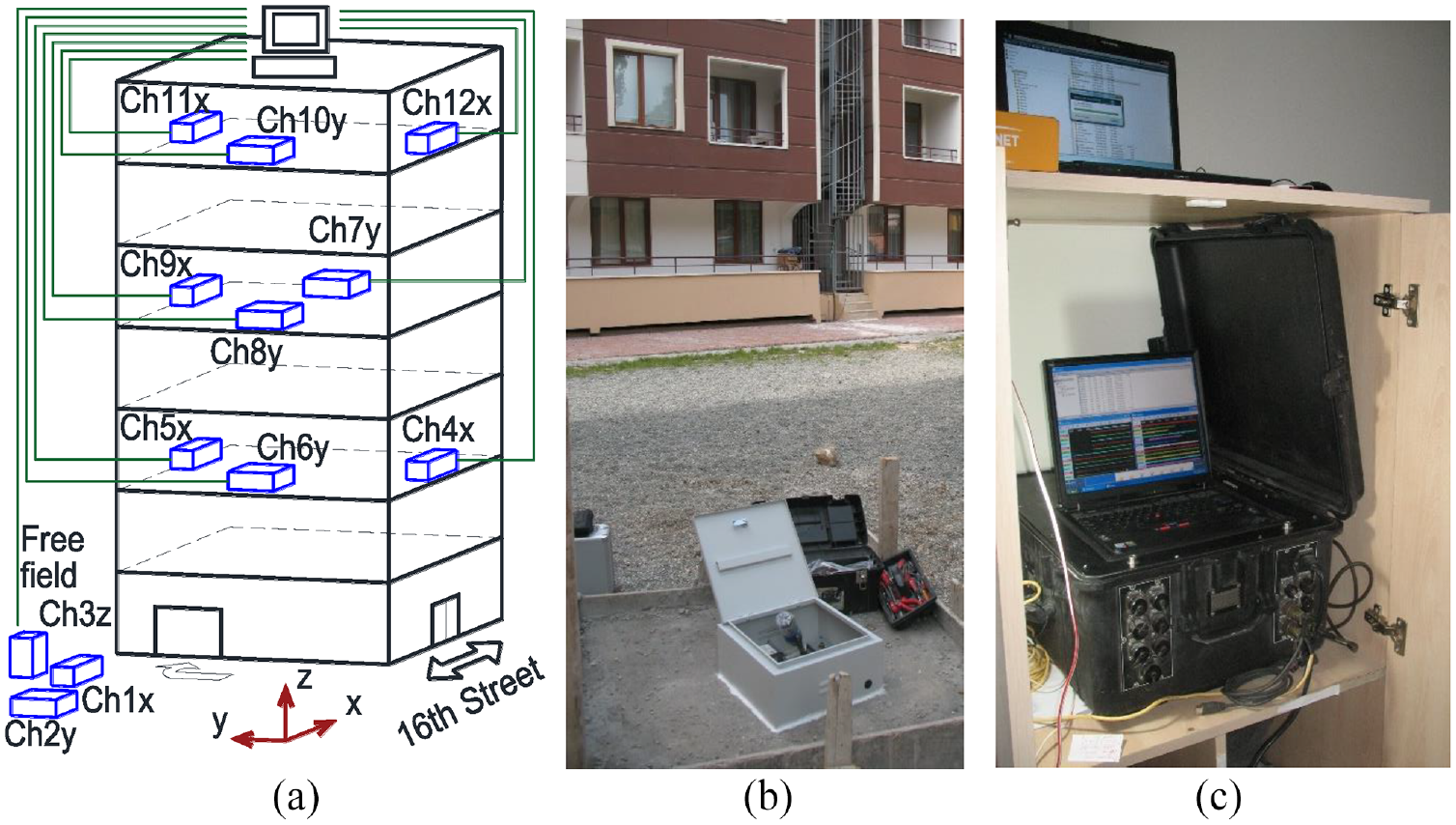
Location and orientation of the accelerometers. (a) Schematic view. (b) Free-field station. (c) Equipment at the roof.
During the monitoring, on February 14, 2014, at 02:33 am local time (00:33 am UTC), an earthquake with a magnitude of Mw 4.5 occurred in Antakya. The epicenter was located at Iskenderun, Korfezi, 67 km from the building, at a depth of 17.5 km (Coord. 36.7218, 36.0273). Table 2 summarizes the vibration periods reported by the accelerometers during the ambient data analysis and the earthquake data recorded (Figure 12). After comparing the dynamic properties before and after the earthquake, it was concluded that the building was not damaged. Further differences would be expected after the building experiences a major earthquake.
Vibration periods computed by the real-time monitoring (Genes et al., 2015)
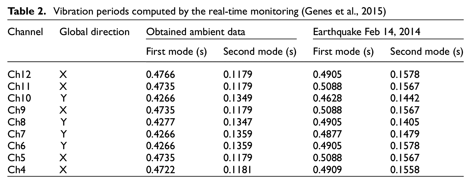
During the aftershock that occurred on February 14, 2014, the computed period was slightly higher than the one obtained from ambient data. It is known that the period computed during a seismic event may varies from the one obtained with ambient data due to the interaction between the structural and non-structural elements, effects of damping, and live loads, among others (Genes et al., 2015; Murià-Vila et al., 2021). Therefore, even though there were differences in the main period, the value of 0.47 s was considered here, as a reasonable reference of the dynamic properties of the building at the pre-earthquake condition.
Nonlinear analysis
3D nonlinear analyses were performed using OpenSees (Mazzoni et al., 2006). Nonlinear beam–column elements were accounted for with plasticity spread throughout the element length. Element torsional properties have been added to the fiber nonlinear beam–column element using the aggregation tool in OpenSees. This model technique has proved to give realistic predictions of the inelastic response. Further details and validation of the model may be found in the work by Uriz and Mahin (2008), Tapia-Hernández, and García-Carrera (2019).
To generate the cross-section of the wide flange beams, three rectangular patches were used: one for the web and two for each flange, as shown in Figure 13a. These patches were discretized into fibers with quadrilateral shapes and six integration points per element. In addition, rigid zones with 10 times the original element’s axial, shear, and bending stiffness were included at the ends of all elements, as depicted in Figure 13b. The beam–column connections of shear tab type were modeled as pins with zero-length rotational spring model, and Steel02 material assigned (Liu and Astaneh-Asl, 2004). Based on the construction process evidence (refer to Figure 8), the joints around the core shear were modeled as a moment-resisting connection.
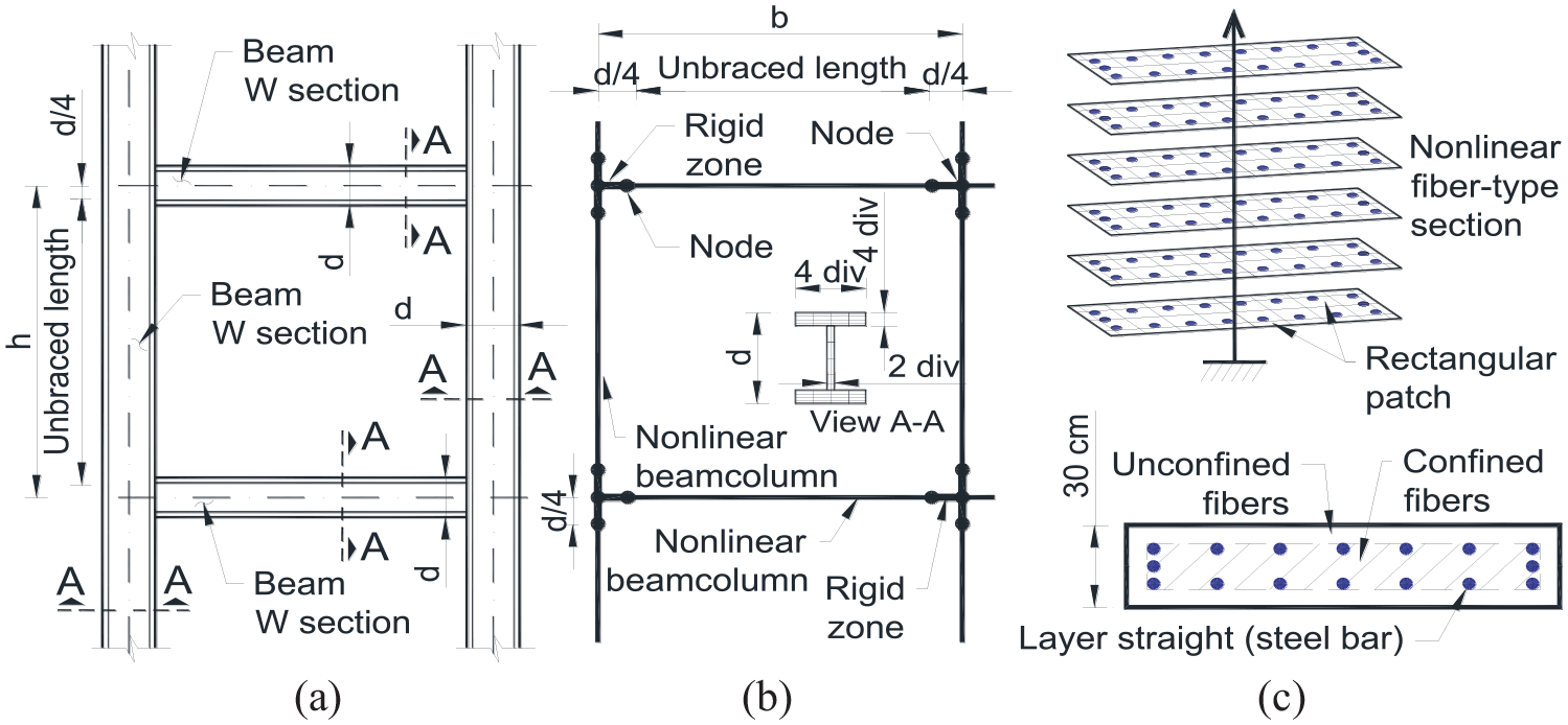
Details of the analytical model in OpenSees. (a) Frame elevation. (b) Nonlinear model for frames. (c) Modeling wall response.
The shear wall response was modeled using Fiber-Type Beam–Column elements, as depicted in Figure 13c. The section was divided into concrete and steel to represent the behavior, with confined and unconfined regions. Concrete regions were generated with rectangular patches, while the straight layer command was used to construct the reinforcing steel bars. UniaxialMaterial objects in OpenSees were used to define the fiber stress–strain relationships (Mazzoni et al., 2006). The Concrete02 model was used for the unconfined concrete fiber section with a concrete compressive strength of f’c = 21 MPa and a concrete strain at compressive strength of ec0 = 0.002. The confined concrete fibers had f’c = 25 MPa and ec0 = 0.004. For the fiber-reinforcing steel sections, the Steel02 model was considered with fy = 410 MPa. Previous studies (e.g. Pugh et al., 2017; Lowes et al., 2019) have demonstrated that OpenSees fiber-type force-based beam–column elements with regularized material models accurately simulate stiffness, strength, and drift capacity for planar and c-shaped reinforced concrete walls.
In the analysis, a single load step is carried out using a load control integrator for the vertical loads, including dead loads, live loads, and the structure’s self-weight. The gravity loads at the roof were 3.84 kPa for dead loads and 0.8 kPa for live loads. For the interstory, the gravitational loads were 4.43 kPa for dead loads and 2.45 kPa for live loads. At this point, the time domain is set to 0.0, and this load is kept constant during the nonlinear dynamic analysis.
The model was analyzed simultaneously under the 10 ground motions in both directions, NS (North–South) and EW (East–West). Nonlinear time-history analyses under selected acceleration records were conducted using OpenSees software (Mazzoni et al., 2006). Peak values of the interstory drift and the demands in columns of the ground level were computed for each time-history analysis to analyze the building response. The discussion below highlights the results of the nearest stations (3123 and 3132) and the two records with the highest ground acceleration (3126 and 3129) to emphasize the trend (see Table 1).
Predictably, the first story (ground floor) reported the peak deformation demands (Figure 14a), as it had the highest interstory height (3.60 m). This observation agrees with the calculation of the lateral stiffness (Figure 6b), where a soft story was identified by comparing story stiffness. Regardless of the distance between the accelerometric station and the building (Table 1), the peak drift demand at the first story occurred approximately at the same time, as shown in Figure 14b. Thus, the structure was identified as a soft-story building as it has a weaker first floor with less lateral stiffness and strength than the other stories. Based on the analyses, it was found that the drift developed in most of the analyses was enough to cause structural damage, according to the evidence reported in experimental tests (e.g. Tapia-Hernández et al., 2022). This observation was consistent with the inspection findings (Figure 9c and e). A slight relationship was noticed between the ground acceleration applied and the developed deformation at the first story (Figure 14c); as the demand acceleration imposed increased, so did the deformation demand.
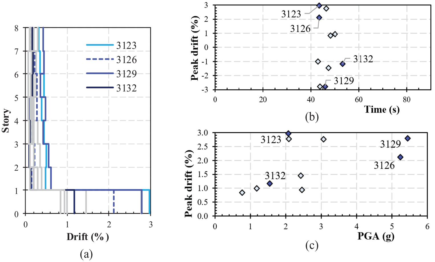
Interstory drifts obtained under the 10 selected records. (a) Peak deformation demands. (b) Peak drift along the records at the first story. (c) Peak drift imposed by the PGA.
The compressive axial load has a negative effect and causes secondary moments; especially, when applied off-center. This can lead to increased lateral deflection, reduced resistance, column stiffness, and stability (Erfani et al., 2017). The gravitational loads considered in the analysis were determined according to the standard codes (such as ASCE 7-22, 2022). No unusual loads were identified during the inspection, only typical residential dead and live loads. The columns failed due to the flexure-compression effects that occurred when the imposed demands exceeded the capacity. For instance, the interaction diagram for the column in axes C-1 (Figure 5c) under the 10 records is shown in Figure 15a, normalized with the expected capacity in compression Rc and bending Mye (AISC 360-2022, 2022). During the field inspections (Figure 7c), this column was identified with the structural damage. According to the results, the damage was caused by an increase in bending demand, further worsened by the fact that the column had a non-compact section.
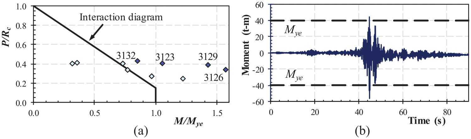
Response of column C-1. (a) Flexure-compression demand under the 10 records. (b) Moment demand along the record of the station 3129.
Figure 15b depicts the evolution of the bending demand in the column of axes C-1 under the ground motion recorded at station 3129, located at a distance of 0.549 km (Table 1). According to the results, the imposed demands on the column are higher than the strength capacity Mye (= SFye, for non-compact sections), which led to inelastic incursion and damage. Unfortunately, the partial collapse prevented the inspections of the interior of the building. However, the findings of the analytical study suggest that some internal columns may have also been damaged.
The analyses emphasize the importance of designing steel members of buildings in seismic regions to have a compact section that fulfills all the requirements for ductile structures in specialized codes. The negative effect of the soft-story mechanism should be explicitly considered and minimized as much as possible.
Conclusion
On February 6, 2023, two significant earthquakes occurred with an epicenter close to Kahramanmaraş, affecting a large region in Turkey and Syria. More than 160,000 buildings collapsed or were severely damaged. Moment-resisting concrete frames, and confined and unconfined masonry were the typical structural systems that were severely damaged by the earthquake. According to the ground motions recorded by the strong-motion network, the imposed seismic demands in many locations were much higher than the design spectra proposed by the current regulation.
In the affected region, a few steel frame buildings existed. Moment-resisting frames with W-sections in beams and columns and truss moment frames were identified. The observed damages in structural and non-structural elements of steel buildings identified during a post-earthquake inspection are presented and discussed in detail.
Steel buildings displayed different levels of performance. Some buildings resisted the earthquake and reported satisfactory behavior with damage in non-structural components and negligible damage in structural elements. In contrast, two buildings reported damage in structural elements, including partial collapse, with severe damage in non-structural components. The failures cannot be dismissed as the result of a unique set of unusual circumstances. They underline the lessons of improper performance, the interaction between the components of steel buildings, and the relevance of strictly following the requirements of specialized codes. The use of compact sections in primary elements, proper erection and construction process, and qualified welding procedures, among other considerations for ductile frames would have been useful to avoid the developed damage.
In particular, the Antakya building provided the opportunity to analyze the failure through a calibrated model from real-time monitoring measured before the earthquake. The analyses offer the chance to study the performance of a building under severe seismic demands when the structure is not adequately detailed for ductile response. Although these aspects might be pointed out previously in experimental tests and analytical studies of its components, on rare occasions, they have been able to be evaluated in a building during an intense earthquake. Based on this study and the post-earthquake observations of damages in steel buildings, the following lessons should be learned:
The building’s improper performance was due to the low redundancy of the shear connections and the slender flanges of the columns (non-compact sections).
There is a need for continuous and strict supervision of the design and construction process by qualified engineers.
The magnitudes in the design spectra established by the local code (TBER-2018) should be re-examined.
Proper infill walls anchorage systems should be implemented to avoid in-plane and out-of-plane infill collapse.
Stricter mandatory reviews should be conducted for buildings with a soft story or another structural irregularity condition, even in low-rise buildings.
Proper structural design should be implemented strictly following the requirements of the specialized seismic provisions for steel buildings.
Footnotes
Acknowledgements
The authors thank the Mexican Society of Earthquake Engineering for their coordination and facilities during the post-earthquake inspections. They also thank the Scientific and Technological Research Council of Turkey (TUBITAK) for the support (grant no. YMAÜ-INTAG I578; Establishing Local Strong-Motion Networks in Turkey) that enabled the monitoring of the Antakya building. The Disaster and Emergency Management Authority (AFAD) recorded the ground motions during the February 6, 2023 earthquakes.
Declaration of conflicting interests
The author(s) declared no potential conflicts of interest with respect to the research, authorship, and/or publication of this article.
Funding
The author(s) received no financial support for the research, authorship, and/or publication of this article.
Research data and code availability
Ground-motion data used in the study are available at https://tadas.afad.gov.tr/list-event. The code spectra are available in ![]() . The discussion is based on a field inspection conducted 7 weeks after the earthquakes. The geographical coordinates are provided, so that interested readers can review complementary information and conditions of the hospitals.
. The discussion is based on a field inspection conducted 7 weeks after the earthquakes. The geographical coordinates are provided, so that interested readers can review complementary information and conditions of the hospitals.