
Abstract
Shake table tests of single degree of freedom elastic/inelastic structures have confirmed that by adding a negative stiffness device (NSD), capable of exhibiting nonlinear elastic negative stiffness, in conjunction with a viscous damper, the acceleration, inter-story drifts, and base shear can be reduced significantly. However, little is known about how the presence of NSD/damper in the first story influences the response of higher stories of a multistory structure. In this paper, shake table test results are presented that demonstrate the advantages of NSD/damper in the first story of a multidegree of freedom, three-story, fixed-base structure (MDOF-3SFS). Results confirm that deployment of NSD/damper at the first story leads to significant reductions of acceleration as well as base shear and inter-story deformations in the MDOF-3SFS. Essentially, an NSD and a damper in the first floor prevents the transmission of the input energy from the ground motion to the second and third story of the multistory structure by deflecting and dissipating energy. If the first-story displacements become excessive, NSD stiffens and prevents collapse. The efficacy of the NSD/damper system is further demonstrated by comparing it with the performance of a structure with passive viscous dampers deployed in the first story. In addition to the reduction of base shear and maximum accelerations, the NSD/damper system also restricts large deformations to the first story only, leading to minimal damage to the whole structure. Finally, an NSD-based bracing system is introduced that can be deployed in new and existing structures.
Introduction
Reinhorn et al. (2005) and Viti et al. (2006) proposed the concept of weakening and damping to reduce the acceleration, base shear, and deformations of a structure. Accelerations experienced by a structure can be reduced by weakening the structure—that is, reducing the strength, which in turn leads to reductions in story forces. Furthermore, by introducing additional supplementary viscous damping, the inter-story drifts can also be reduced simultaneously. Moreover, the approach described in ASCE 7, chapter 18 (2005), for the design of structures with damping systems is based on the concept of reduced strength and stiffness and the addition of damping to achieve the same objective for new construction.
Although weakening and damping of structures is capable of reducing both the accelerations and the inter-story deformations, weakening the structures leads to early yielding/inelastic behavior of structural systems resulting in damage, inelastic excursions, and permanent deformation. To avoid modifying the structural properties, Nagarajaiah et al. (2010) proposed the concept of apparent weakening to emulate a yielding system by adding a complementary negative stiffness device (NSD) without altering the structural properties. The NSD used in this study is similar to the idea proposed by Nagarajaiah and Reinhorn (1994) and Constantinou et al. (2014). Unlike the concept of conventional weakening and damping, where the main structural system strength itself is reduced (or weakened) by inelastic action, the structure and NSD assembly in apparent weakening produces effects mimicking early yielding, but the original structural system remains nearly elastic or may have mild yielding (Pasala et al., 2013)—as compared to heavy yielding accompanied with damage due to conventional weakening and damping.
Negative stiffness devices lately have been used for various other applications apart from seismic protection. Nagarajaiah et al. (2022b) demonstrated the reduction of transmissibility of an SDOF system analytically and numerically when the SDOF system is equipped with a negative stiffness device and supplemental damping. Salvatore et al. (2022) perform a detailed study during which they demonstrate the reduction of the structural response to the inclusion of a negative stiffness system and supplemental hysteretic/viscous damping using frequency response functions. The damping enhancement property of negative stiffness systems was demonstrated for cables by Chen et al. (2015). Wang et al. (2019) demonstrated that a Maxwell element constituted by a flexibly supported viscous damper and a negative stiffness device leads to the amplification of stroke of dashpot and, thus, leads to amplified energy dissipation and structural response reduction. Nagarajaiah et al. (2022a) proposed the use of inerter and negative stiffness devices to produce frequency-independent damping capabilities using viscous dampers in high-rise structures and large-span bridges. Rate-independent linear damping devices have been proposed by using inerter elements and negative stiffness elements in various configurations along with their efficacy in seismic protection (Luo et al., 2023; Wu et al., 2023).
The authors have previously demonstrated apparent yielding and apparent weakening through (1) conceptual analytical studies on a fixed-base SDOF system (Pasala et al., 2012), (2) experimental and analytical studies on a simulated, bilinear-elastic, fixed-base SDOF structure (Pasala et al., 2013), and (3) experimental and analytical studies on a yielding inelastic fixed-base SDOF structure (Pasala et al., 2014). However, little is known about the influence of NSD on multidegree-of-freedom (MDOF) structures. Hence, the focus of the current study is the influence of deployment of an NSD in the first story on the response of higher stories.
In this paper, results from the shake table tests on an MDOF three-story, fixed-base structure (MDOF-3SFS) with NSD and a viscous damper in the first story are presented. Analytical models were developed and calibrated at the component level and also at assembly level to capture the observed experimental behavior by the authors in previous studies. These models are adapted to construct the MDOF system (Pasala et al., 2012, 2013, 2014; Sarlis et al., 2012). Since the columns were yielding (and becoming inelastic) and had to be replaced for every test, which is expensive, the experiments were performed only on either the MDOF-3SFS, NSD, or damper assembly in strong earthquakes (wherein damper stroke was within limits) or only on the MDOF-3SFS and NSD assembly for very strong earthquakes (wherein damper stroke limits were exceeded). Response of four different systems: (1) MDOF-3SFS or the base structure (BS); (2) MDOF-3SFS and NSD assembly (NS); (3) MDOF-3SFS, NSD, and damper assembly (AS); and (4) MDOF-3SFS and damper (PS) are generated either experimentally, in cases where possible, or using calibrated analytical models (Pasala et al., 2012, 2013, 2014; Sarlis et al., 2012) and compared in detail to highlight the advantages of apparent weakening with damping in fixed-base, multistory structures. It is found that NSD and damper on the first floor prevent the transmission of the input energy from the ground motion to the second and third story of the MDOF structure by deflecting and dissipating energy. Essentially, a first-story isolation is created; however, if the first story displacements become excessive, NSD stiffens and prevents collapse. To further demonstrate the efficacy of deploying an NSD and a damper in the first story, the performance of the calibrated analytical model is further tested for a suite of strong ground motions.
Adaptive negative stiffness system
The full details of the adaptive negative stiffness and assembly behavior in simulated bilinear-elastic and inelastic SDOF structures can be found in Pasala et al. (2012, 2013, 2014) and Sarlis et al. (2012). In the current study, the investigation is extended to MDOF structures. A brief description of the working principle of NSD, presented in Pasala et al. (2012, 2013, 2014) and Sarlis et al. (2012), in inelastic structures and several issues pertaining to the permanent drift in the assembly are discussed. For a more complete description of the structure, NSD, and assembly, the reader is referred to the authors’ previous work (Pasala et al., 2012, 2013, 2014) and Sarlis et al. (2012).
Apparent weakening in inelastic structures
The force-displacement (F-D) curves of a structure with inelastic behavior, NSD, and assembly is shown in Figure 1. Figure 1a shows the idea of apparent yielding creating a nonlinear-elastic structure, while the main structure remains nearly linear-elastic (Pasala et al. 2013, 2014). Figure 1b and c shows the idea of apparent weakening creating an inelastic assembly, while the main structure becomes inelastic. Four critical points are marked on the F-D curves in Figure 1b, and the characteristic features of these points are described next:
At point 1,
At point 2, the structure yields (marked as “yield point”). Beyond
At point 3, NSD starts stiffening; tangential stiffness of NSD becomes positive beyond point 3. Thus, for displacements larger than
At point 4, NSD spring loses all the pre-compression force; NSD exerts zero horizontal force. Thus, at displacement
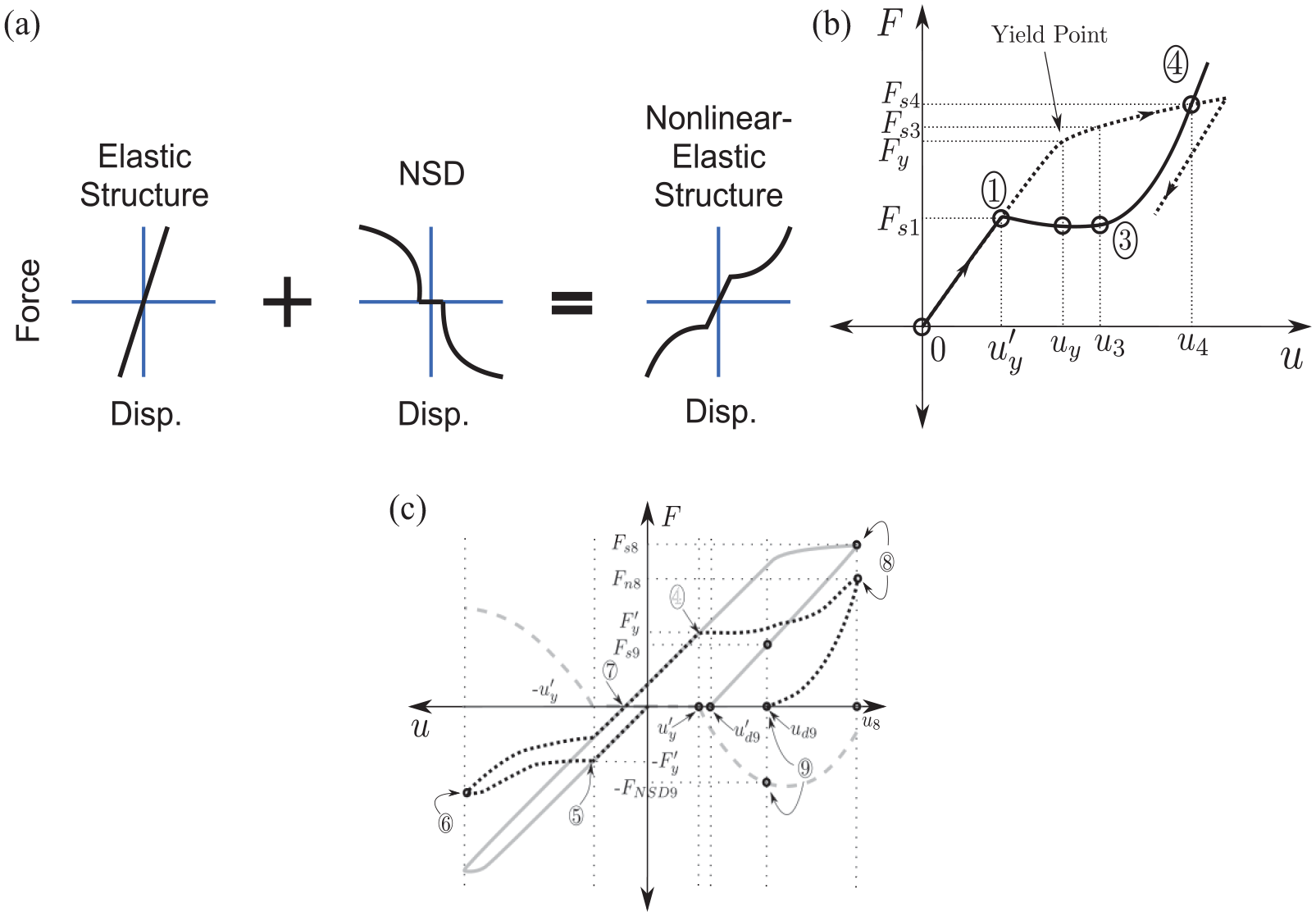
(a) The concept of apparent weakening in force displacement (F-D) behavior of nonlinear-elastic (Pasala et al., 2012) and inelastic (bottom) ( Pasala et al., 2013, 2014). Structures with NSD:(b) inelastic structure (solid line) with NSD (dashed line) and assembly (dotted line) and (c) inelastic structure (solid line) with NSD (dashed line) and F-D of assembly (dotted line) with permanent drift.
Yield displacement of the structure should be chosen as close to the stiffening point of NSD,
Permanent drift in yielding systems
The F-D behavior of the structure and NSD assembly for the mild-yielding case and heavy-yielding case is shown in Figure 1c. A load case with a half-pulse cycle in the negative direction and another half-pulse cycle of higher magnitude in the positive direction helps obtain the necessary F-D behavior in the inelastic structure, NSD, and assembly. For a half pulse cycle in the negative direction, the assembly first deforms in the negative direction leading to mild yielding; after the deformation of the structure increases beyond
Next, the heavy yielding condition in which
It should be noted that the assembly force is zero at point 9, with the force in the primary structure,
Experimental setup
The test structure in this study is an MDOF one-third scale, three-story, one-bay fixed base structure (Figure 2). The structure is similar to the one used previously to demonstrate apparent weakening in SDOF elastic and inelastic structures (Pasala et al., 2014)—in which the second and third story were braced, preventing MDOF behavior. The moment frames of the MDOF structure in the current study have no braces in the second and third floors (as evident in Figure 2). Since the details pertaining to the experimental setup and connections between various components have been extensively described previously, the readers are referred to authors’ previous work (Pasala et al., 2014). Henceforth, the structure is referred to as 3SFS or MDOF-3SFS. A brief description of the main components in 3SFS is given next for reader’s convenience.
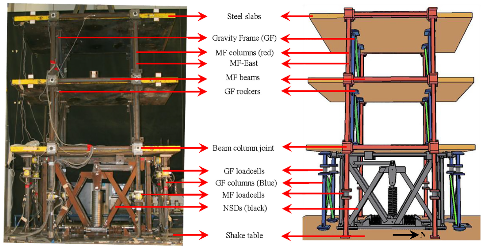
(left) Experimental setup of the MDOF three-story frame structure (MDOF-3SFS or simply 3SFS) installed on the shake table. (right) Schematic diagram of the elevation of 3SFS.
Elevation, both the actual photograph and the schematic, of the MDOF-3SFS without braces is shown in Figure 2; the elements in the schematic are color-coded. MDOF-3SFS was developed and first built to study structural systems in the near collapse state. MDOF-3SFS has two independent support systems: (1) the moment-resisting frame or simply the moment frame (MF) to bear the lateral inertial forces exerted on the structure—MF frame is replaceable, and (2) a gravity frame (GF) to carry the gravity load of the entire structure and prevent torsion. As shown in Figure 2, GF frame does not carry a lateral load and thus is never replaced during the experiments. The gravity load of the structure is due to three 3.5
3SFS has two moment-resisting frames (red colored frames in Figure 2) sandwiching the steel slabs along the east-west (left-right as shown) direction. The columns and beams in MF are connected using a beam-column block. The beam-column block is designed to transfer only the lateral load of the steel plates to the moment frame. GF is the vertical load support system designed to carry the gravity load, and it cannot provide any resistance to the inertial forces of the steel slabs. Two sets of gravity frames are placed in the clear space of each story, perpendicular to the plane of motion, symmetrically on either side of the center line of steel slabs. The gravity frame consists of two columns (blue color columns in Figure 2); the opposite corners of the columns are connected with braces (green color in Figure 2) to prevent torsion in the 3SFS, and the ends of the gravity columns have rockers.
Negative stiffness device
The negative stiffness device (NSD) in the first story, shown in Figure 2, is a passive device, and it exerts force on the structure that assists motion (due to the pre-compression in the spring till it is completely lost) instead of resisting it as in the case of a positive stiffness spring (Pasala et al., 2012; Pasala, 2012). NSD exerts negative tangential stiffness, and as a result, the assembly stiffness is reduced. In this experimental study, two NSDs are needed to generate the desired negative stiffness (NSD-east or left and NSD-west or right). Figure 2 depicts the NSDs (one in the front and the other in the back—not visible in figure 2) installed in the first story. The NSD was developed by the authors (Sarlis, 2012) and fabricated for this project by Taylor Devices Inc.
Apparent weakening in the first story of MDOF-3SFS is achieved using two NSDs. Although MDOF-3SFS is an inelastic system, preliminary experimental studies have revealed that the strength-reduction factor of the MDOF-3SFS is only 1.25 (
there is a strength reduction factor of MDOF-3SFS and NSD assembly,
assembly exhibits very low tangential stiffness for deformations
stiffening of NSDs starts close to the yield displacement of the primary structure, and
MDOF-3SFS and NSD assembly has a strength reduction factor of
Viscous damper
A viscous damper developed by Taylor Devices Inc. is used in this experimental study. A damper with 20% of the critical damping is found to be optimal for the MDOF-3SFS to achieve the desired reduction in forces and displacements of AS (Pasala et al., 2013). The damper exhibits almost a linear force-velocity behavior and has a damping coefficient of
Analytical modeling
The columns of lateral load-bearing MF were yielding and had to be replaced for every test, which is expensive; hence, the experiments were performed only on the MDOF-3SFS, NSD, and damper assembly in strong earthquakes (wherein damper stroke was within limits of ± 2 in) or on the MDOF-3SFS and NSD assembly for very strong earthquakes (wherein damper stroke limit of ±2 in was exceeded). As mentioned earlier, to evaluate the effectiveness of NSD, the responses of four systems—BS, PS, NS, and AS—must be compared. So, the responses of all four systems—in cases where experiments could not be performed due to the expensive nature of the lateral MF replacement, had to be simulated using the analytical models. To ensure the consistency in modeling, first the analytical models for the components were developed from first principles and the unknown parameters in the models were obtained by calibrating with the experimental results of component testing (Pasala et al., 2012, 2013, 2014; Sarlis et al., 2012). The analytical models developed were calibrated using one set of experimental results (Pasala et al., 2012, 2013, 2014; Sarlis et al., 2012). Using the calibrated models, the predicted behavior of the components were also compared with another set of experimental results, and they were found to be in good agreement (Pasala et al., 2012, 2013, 2014; Sarlis et al., 2012).
MDOF-Three Story Frame Structure
Since the primary structure (MF) experiences yielding and inelastic behavior in the experiments carried out in this study, the story stiffness was modeled using the Sivaselvan-Reinhorn model (SR model) (Sivaselvan and Reinhorn, 2000). Also, frictional damping was observed in NSD experiments due to friction in NSD joints (Sarlis, 2012), which was also captured using the Sivaselvan-Reinhorn model. For details pertaining to the analytical models and the values of parameters used in the models, readers are referred to Pasala et al. (2012, 2013, 2014) and Sarlis et al. (2012).
The measured weight of steel slabs in each story is
Negative stiffness device and viscous damper
Complete analytical modeling details of the NSD (Pasala et al., 2012, 2013, 2014; Sarlis et al. 2012) and the comparisons between the experimental force-deformation behavior of NSD-east and NSD-west with the simulated behavior can be found in Pasala et al. (2012, 2013, 2014) and Sarlis et al. (2012). The asymmetry in the F-D behavior of NSD due to the fabrication imperfections is addressed by Pasala et al. (2012).
The observed force-velocity behavior of the viscous damper is linear for velocities less than 10

Experimental and simulated results
The experimental results of two tests are presented: (1) 3SFS, NSDs, and damper assembly (AS) for Pacoima ground motion with a peak ground acceleration (PGA) of
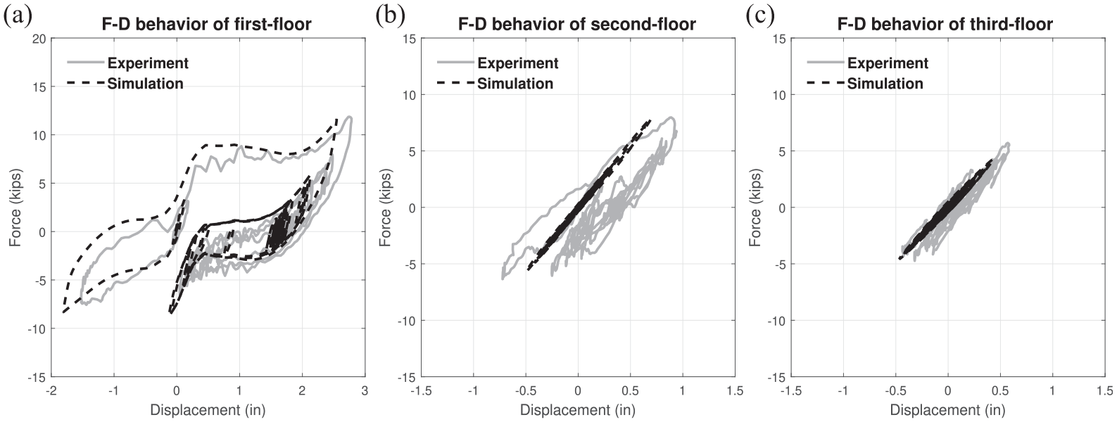
First, the impact of NSD in 3SFS for moderate ground motions is investigated. Force-deformation (F-D) behavior of all the three stories, comparing the experimental and simulated results for Pacoima ground motion
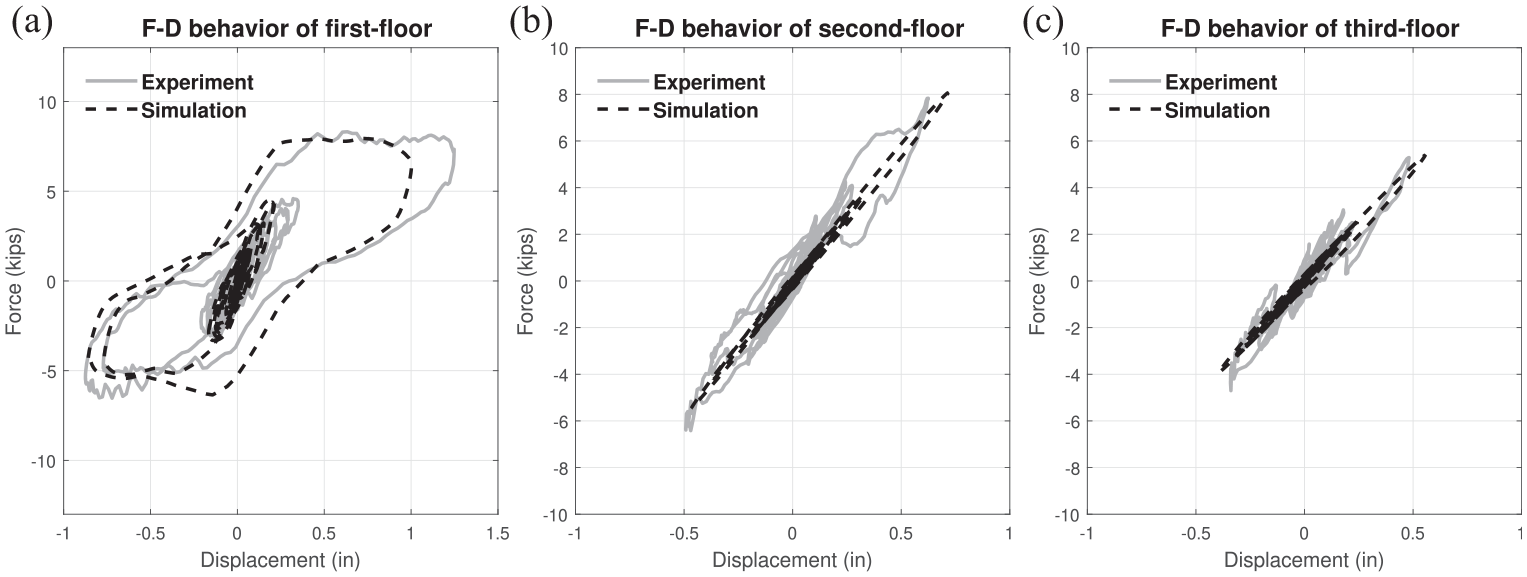
Comparison of the experimental and predicted force-deformation behavior of the stories for the AS case under Pacoima ground-motion,
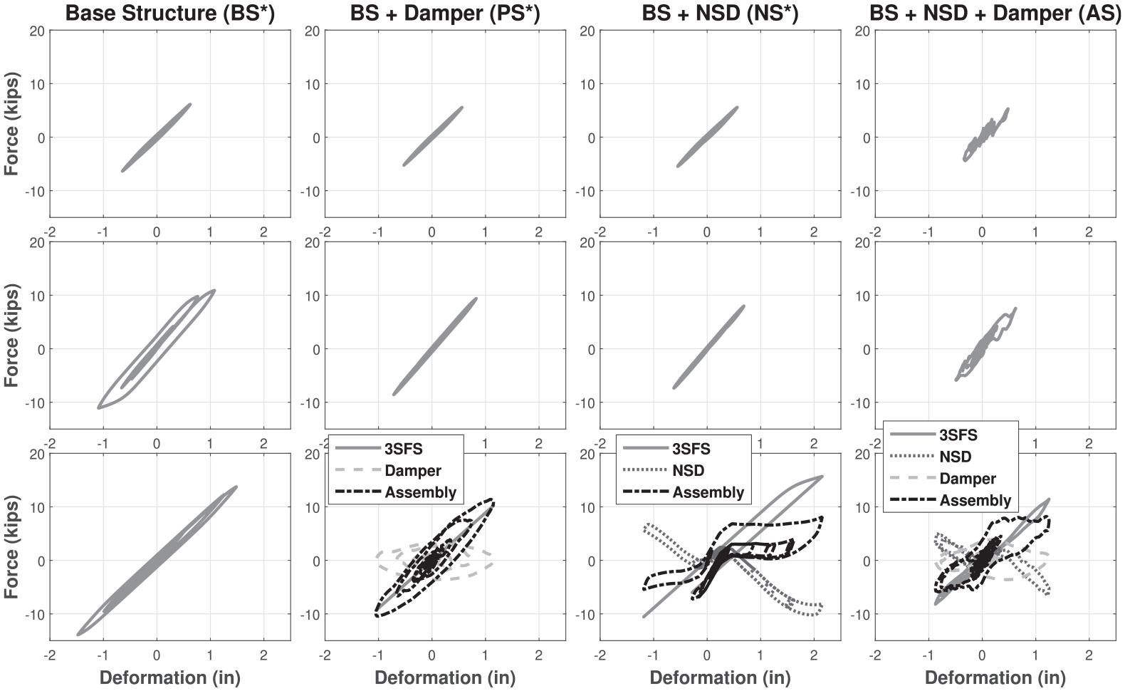
Comparison of the force-deformation behavior of the three stories (third, top; first, bottom) in BS, PS (BS+ Damper), NS (BS+NSD), and AS (BS+NSD+Damper) for Pacoima ground-motion (
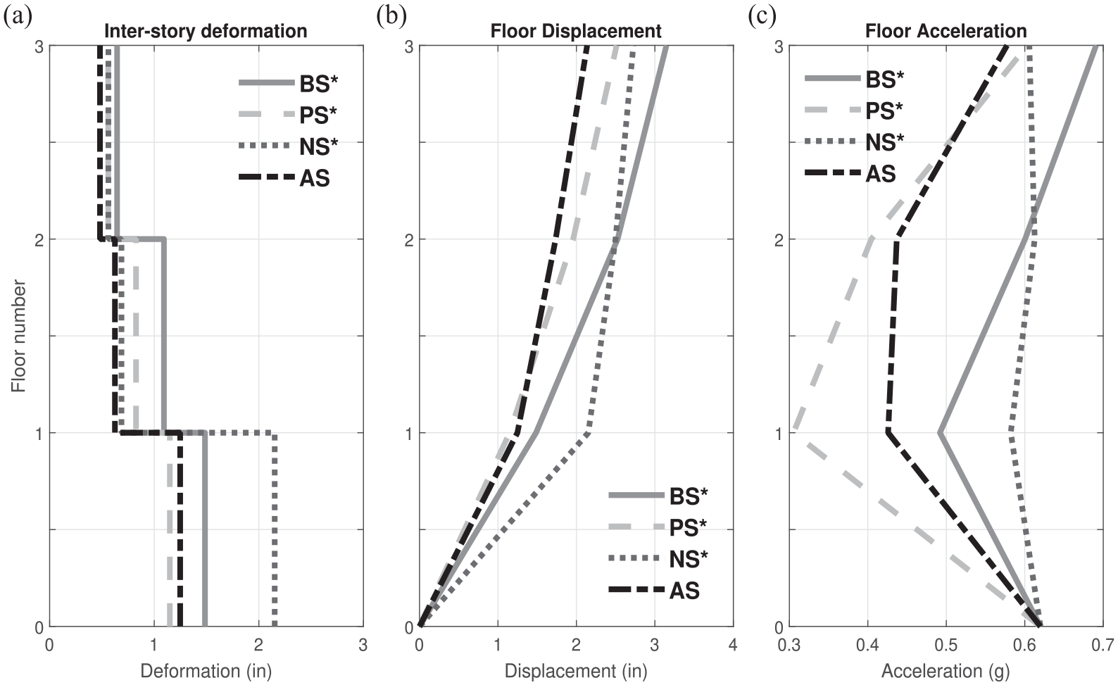
Comparison of the maximum response for Pacoima ground-motion (PGA = 0.62 g): (a) inter-story deformation, (b) floor displacement, and (c) floor-acceleration (* denotes simulation results; otherwise, experimental results).
Comparison of the experimental and predicted force-deformation behavior of the stories for NS case under Pacoima ground-motion
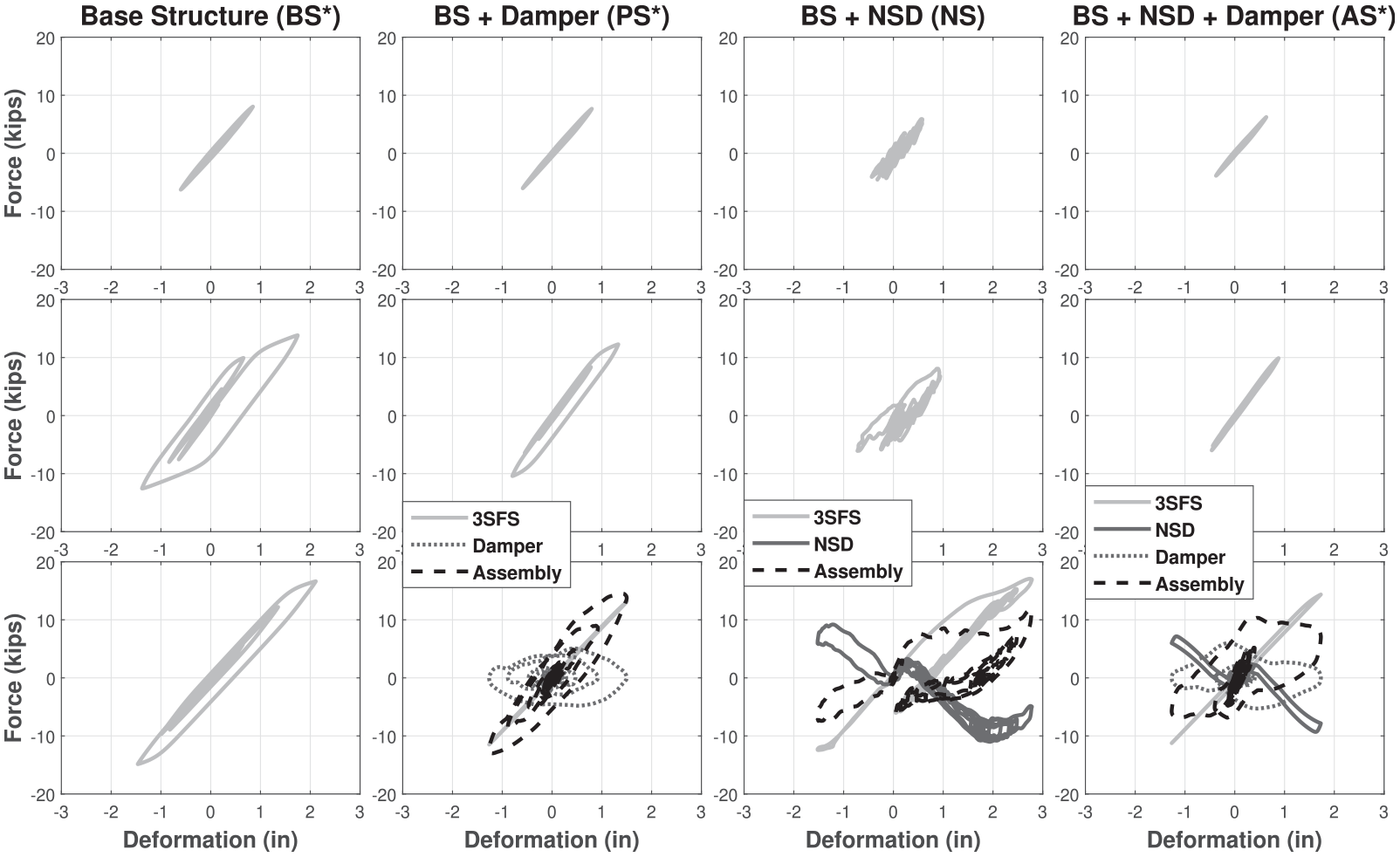
Comparison of the force-deformation behavior of the three stories in BS, PS, NS, and AS for Pacoima ground-motion
Comparison of the maximum response for Pacoima ground-motion (
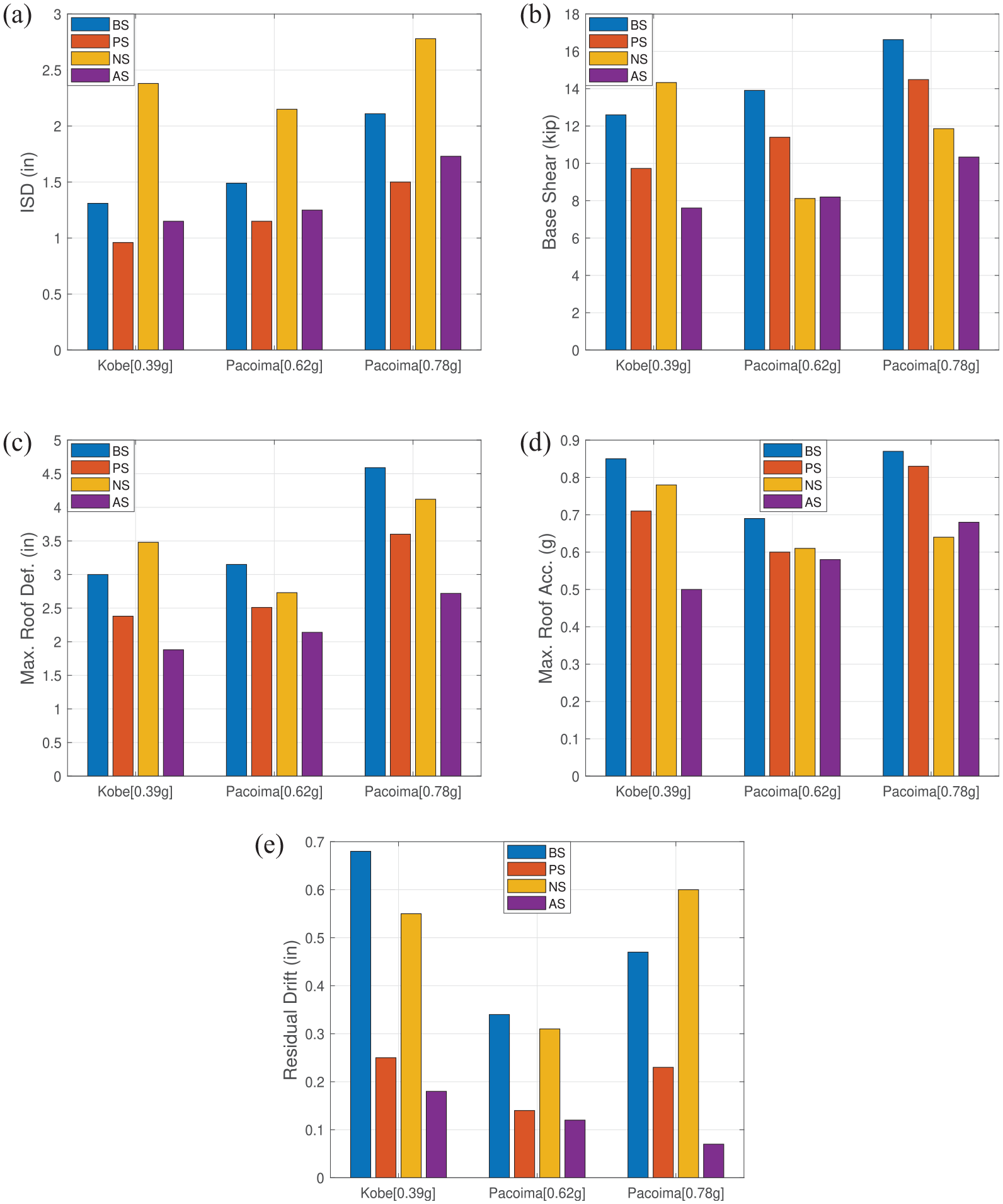
Bar graphs summarizing the peak response for four cases and three ground motions: (a) max. inter-story deformation, (b) max. base shear, (c) max. roof deformation, (d) max. roof acceleration and (e) permanent deformation.
Figure 4 shows that the first and second stories of BS will yield the Pacoima ground motion at a PGA of
The profile of maximum inter-story deformation, maximum floor displacement with respect to the shake table, and maximum floor acceleration of all three stories are shown in Figure 5. The inter-story deformation of the NS and AS is reduced in the second and third stories, as evident in Figure 5a. The deformation and acceleration of the first story have increased with the addition of NSDs, but the relative displacement and acceleration, as compared to the first floor, have reduced over the two stories above it (almost moving as a rigid body). In essence, the first story behaves like an isolation system, while the second and third story’s drift and accelerations are reduced significantly. With the addition of NSD and damper to BS–case AS–the first story deformation, accelerations are reduced as compared to NS (with only BS+NSD) yet retain the beneficial effect of reduced inter-story drift in the second and third stories. As a result, the roof acceleration in AS is 30% less than BS, and the acceleration in NS is 15% smaller than the BS, as evident in Figure 5c. The roof displacement in AS is 30% less than the BS and 10% less than the NS, as evident in Figure 5b; however, inter-story drift in the first story of NS case is 40% more than the other three systems. The first story isolation effect is clearly evident in Figure 5. Next, the behavior of NS and AS is investigated for more severe ground motion (Pacoima ground motion with PGA of
The shake-table test is performed on the 3SFS and NSDs assembly (NS), and the observed response in the NS case is compared with simulation results in Figure 6. F-D behavior of all three stories comparing the experimental and simulated results are separately shown in Figure 6. The overall comparison of F-D behavior in the experimental and simulated cases, shown in Figure 6, is satisfactory. Only the first story had load cells to measure inter-story shear force directly. Again, it is noted that the measured F-D behavior in the second and third stories is noisy because it is computed (not measured) from second- and third-floor measured acceleration; however, the average slope of the experimental results matches with the simulated results, indicating that the two stories are nearly linear. The first story deformed in the negative-loading cycle, first with mild yielding, and then it yielded heavily in the positive-loading cycle (inelastic deformation of more than 1.6 in), as shown in Figure 6a. Due to the permanent drift in the first story, there is slight rigid body rotation in the second and third stories; as a result, their F-D behavior appears to have a permanent drift of 0.4 in, as shown in Figure 6b and c—note the peak displacement is less than the yield displacement of 0.95 in (hence no yielding). From the measured and simulated F-D behavior shown in Figure 6a, it is clear that the NSDs enter the stiffening region. The tangential stiffness of the assembly in the first story reduces significantly from 0.35 in up to 2 in due to the presence of NSDs, and beyond 2 in, it increases again.
Overall, from Figure 6, the analytical models were able to capture the observed experimental behavior reasonably well, even when the primary structure yielded significantly. Using the ground acceleration and the shake-table rocking data measured during the shake-table test, the behavior of BS, PS, and AS cases are predicted, and the F-D behavior of all four systems is shown separately in Figure 7.
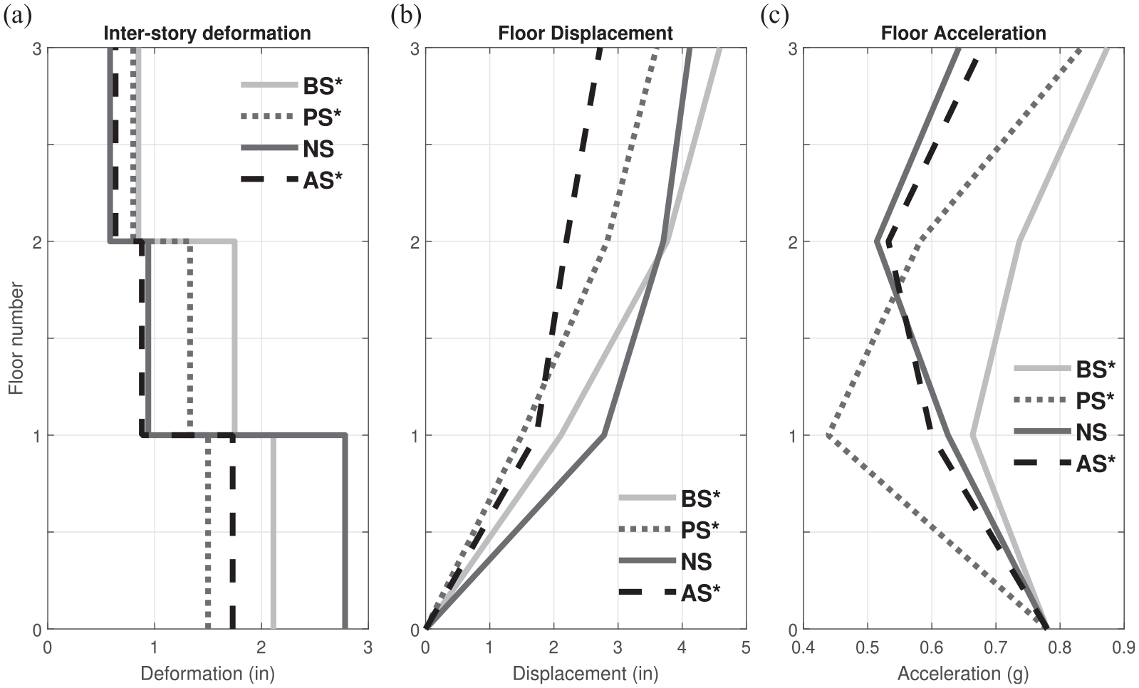
Figure 7 shows that the first and second stories of BS yield significantly for the severe Pacoima ground motion, with PGA of
The profile of maximum inter-story deformation, maximum floor displacement with respect to the shake table, and the maximum floor acceleration of all three floors are shown in Figure 8 for the severe Pacoima ground motion, with PGA of
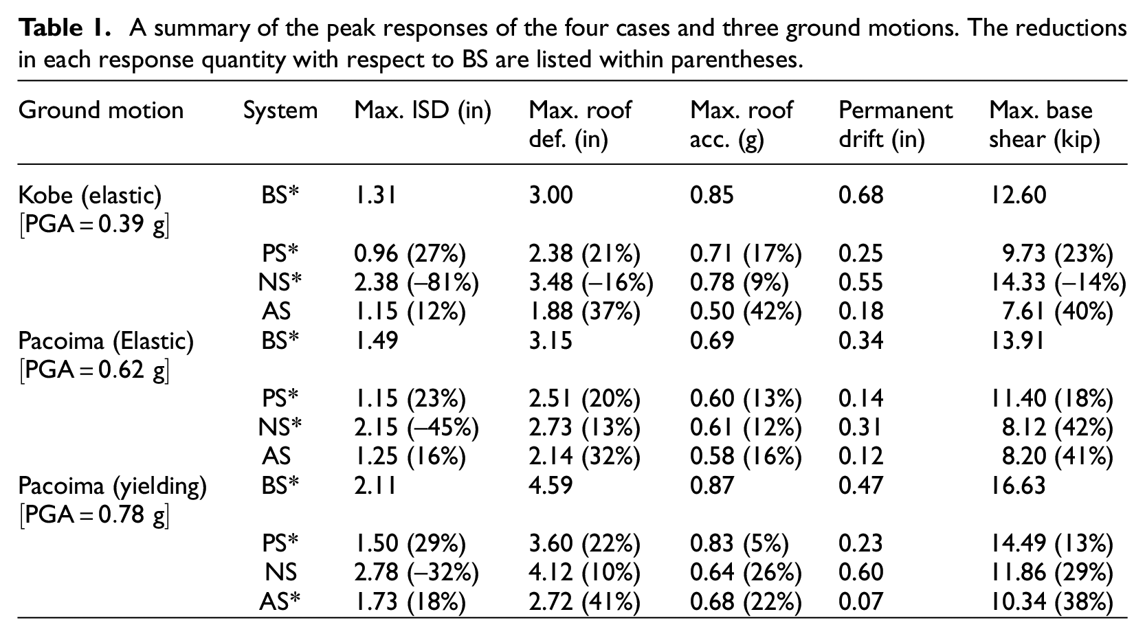
A summary of the peak responses of the four cases and three ground motions. The reductions in each response quantity with respect to BS are listed within parentheses.
The results so far are summarized next:
Addition of NSD with damper (AS) in the first story will reduce the transfer of input energy from the ground motion to the second and third stories of the MDOF structure, essentially acting like a first-story isolation system. Consequently, the inter-story deformation, acceleration of all stories, and base shear are reduced, particularly in very strong ground motion cases with PGA of 0.78
Addition of a damper (PS case) at the first story can control the deformations at the installation level, but the structure experiences only slightly smaller base-shear and inter-story deformations in the second and third stories as compared to the base structure (BS case). This is because of the larger damping forces experienced in the first story at higher velocities due to the nonlinearity in the damper (evident at higher velocities) used in the current study. A passive damper, with carefully chosen nonlinear characteristics (smaller damping forces) at higher velocities in PS and AS may result in much smaller base-shear than the bare structure, which could be the subject of a future study.
By incorporating NSDs and damper (AS) together in the first story of the MDOF structure, all the response characteristics can be consistently reduced, and the higher stories’ can be isolated from the effects of strong ground motion.
Further corroborative simulations
In this section, the analytical model developed in the preceding section is used to further demonstrate the efficacy of the AS system with respect to BS and PS when subjected to severe ground motions. The ground motions used in this section are shown in Figure 10 along with the respective PGAs.
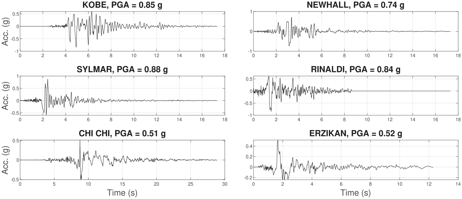
All the ground motions used for response simulation in this section.
Similar to the preceding discussion, various performance metrics for each system are compared. In addition to comparing the maximum story accelerations and base shears, a new performance metric is proposed herein. It is a function of the maximum inter-story drift of each floor, and it will be referred to as the inelasticity parameter or
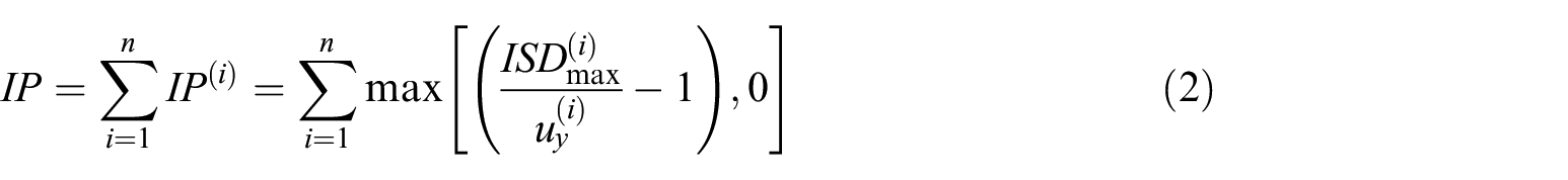
where
Figures 11 and 12 show various response quantities of the different structures when subjected to the severe ground motions shown in Figure 10 with different PGA scale factors (SF). As expected, AS helps achieve lower base shears as well as maximum accelerations compared to both PS and AS. In the third row of Figures 11 and 12,
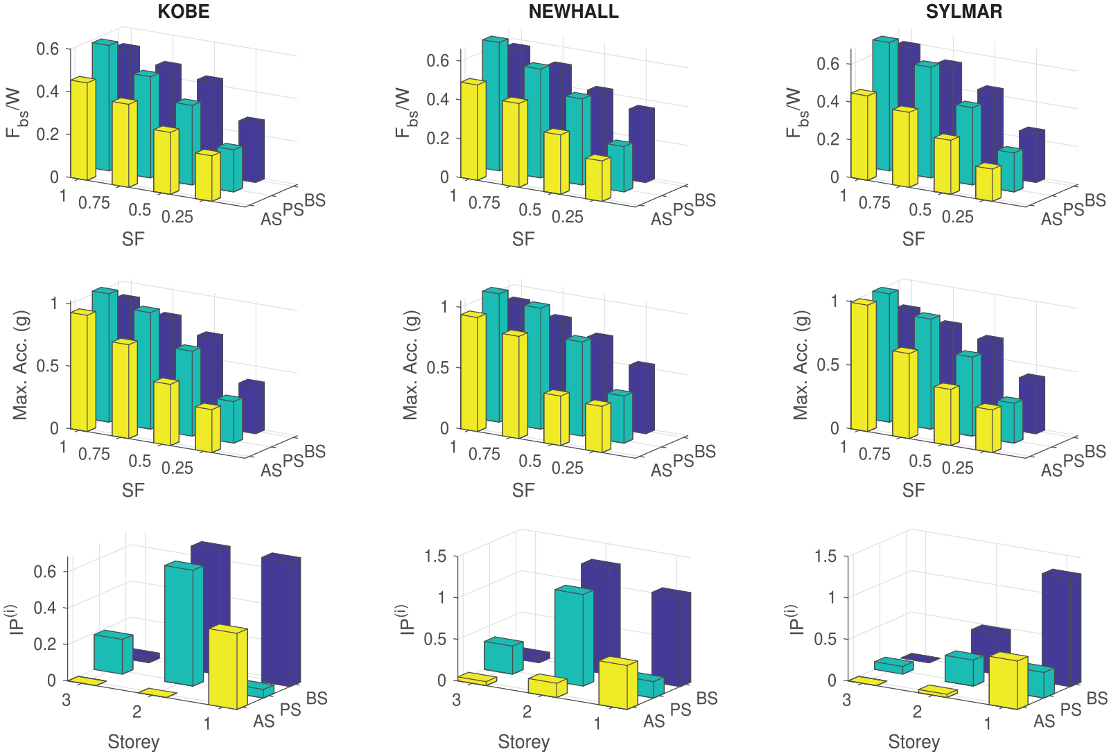
Response quantities for Kobe, Newhall, and Sylmar ground motions.
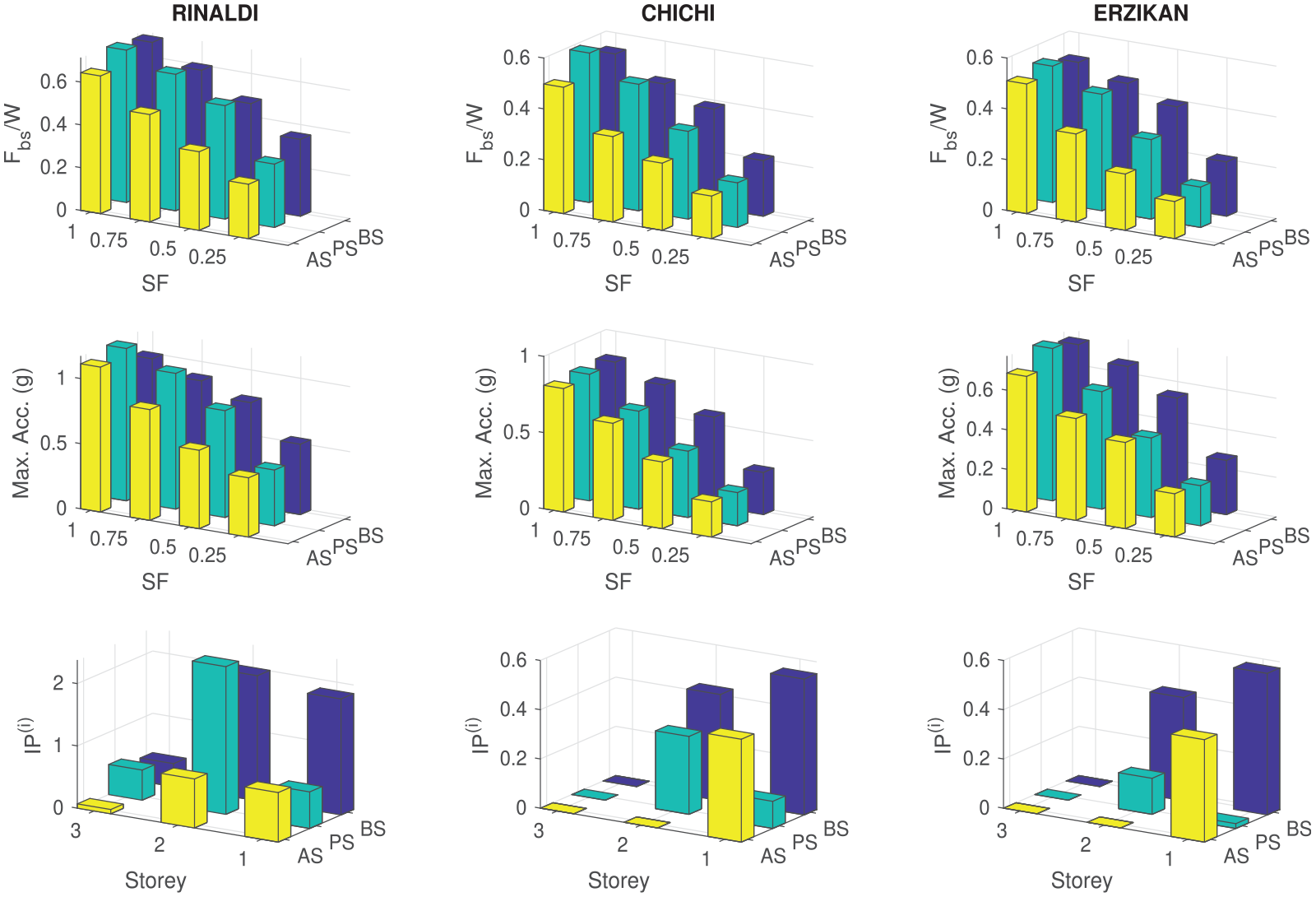
Response quantities for Rinaldi, Chi chi, and Erzikan ground motions.
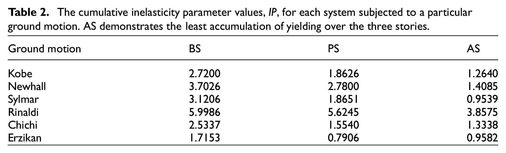
The cumulative inelasticity parameter values,
This restriction of yielding to the first story can be further observed by studying the force versus deformation of each story for all the ground motions as shown in Figures 13 and 14. Clearly, the extent of yielding is significantly reduced for the higher stories in AS with respect to BS and PS.
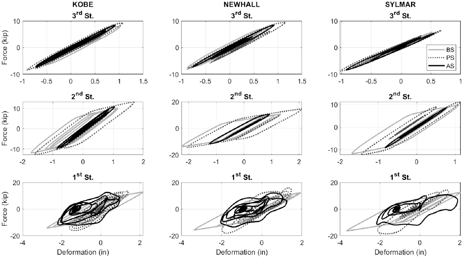
Force deformation plots for each story for Kobe, Newhall, and Sylmar ground motions.
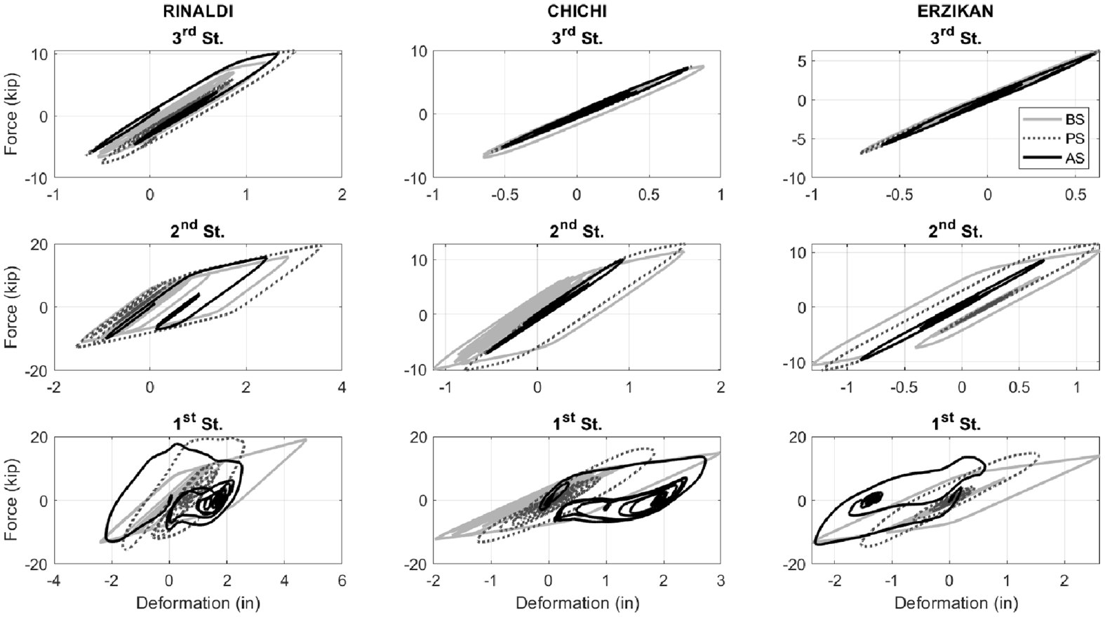
Force deformation plots for each story for Rinaldi, Chi chi, and Erzikan ground motions.
This paper focuses on experimental and analytical studies demonstrating the response behavior of the first and higher stories of MDOF with NSDs and damper only in the first story. It is possible to reduce the response of all the stories’ of the MDOF system by adding appropriately designed NSDs with variable properties at many more stories (Nagarajaiah and Sen, 2020; Pasala et al., 2012).
Negative stiffness brace
Negative stiffness brace (NSB) is the improved version of the NSD, as it can be installed as easily as a brace and works on the same principle as NSD (Sarlis et al., 2015). It also has a higher force magnification factor and, therefore, warrants a pre-compressed spring with lower stiffness. Like NSD, NSB also has precompressed springs that provide the negative stiffness and gap-spring assemblies that negate the effect of negative springs for low displacements. The schematic of NSB and how it can be mounted on a frame is shown in Figure 15a. Using a compact arrangement of pre-compressed springs and gap-spring assembly, the device is built as a brace, allowing for an easy and compact installation. Figure 15b shows the deformed shape of the frame along with the deformation in the brace. The prototype of NSB is shown in Figure 16a along with the arrangement of the pre-compressed springs and gap-spring assembly (GSA) in the inset. Using the manufactured NSB, the normalized force-displacement of NSB (i.e., without GSAs) obtained from the experiment is shown in Figure 16b. The force in Figure 16b is normalized with the pre-compression force of the springs, and displacement is normalized with the pre-compression displacement of the springs. The overall behavior of NSB is very similar to NSD, exhibiting a true negative stiffness until a certain displacement followed by large positive stiffness for large displacements. For the analytical model, as well as further details, the readers are referred to Herkal and Nagarajaiah (ASCE Journal of Structural Engineering, under review, 2024).
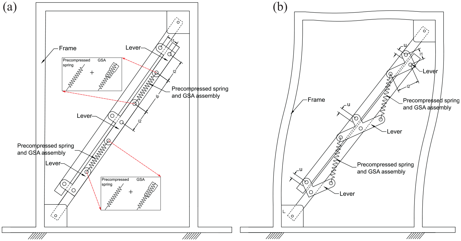
(a) Schematic of NSB mounted on a frame. (b) Schematic of the deformed shape of the frame along with the deformed shape of NSB.
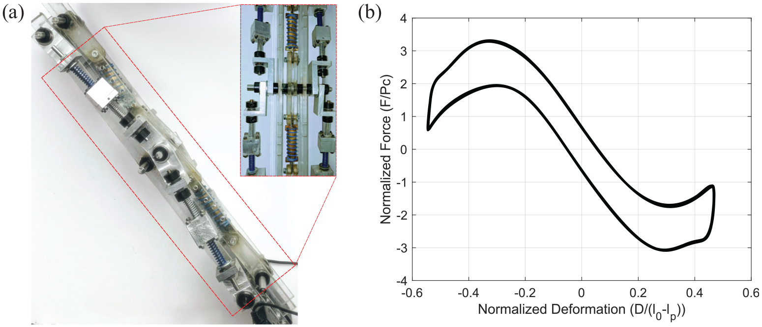
(a) The prototype of NSB. (b) The force-displacement of NSB.
Conclusion
The advantages of using NSDs in the first story of an MDOF yielding/inelastic structure are demonstrated through experimental and analytical studies. Shake-table studies have been performed on an MDOF, three-story, fixed-base structure with two NSDs and a viscous damper in the first story. Experimental results prove that the addition of NSDs in the first story will reduce the input energy transfer to the superstructure (higher DOF). However, the first story is subjected to large inter-story deformation due to the reduction in stiffness with the addition of only NSDs in the first story. But by adding a viscous damper along with the NSDs in the first story, the inter-story deformations of the MDOF can be controlled without increasing the base shear and roof accelerations.
In general, it has been confirmed from shake-table studies that story response (story shear and inter-story response) at the installation level will be reduced in an MDOF system because of the addition of NSD and passive damper in that story. Additionally, the response of the superstructure in higher stories of the MDOF—above the first story in which the NSDs and damper are installed—are also reduced, essentially behaving like an isolation system in the first story. If the deformation response of the first story becomes excessive due to yielding, the NSDs can stiffen and prevent collapse.
The structure tested in this study is an MDOF-three-story structure (MDOF-3SFS or simply 3SFS) with NSDs and damper in the first story. Experimental results of 3SFS have shown that the first-story deformations and the base shear can be reduced by 15% and 40%, respectively, with the addition of NSD and passive damper in the first story. Roof accelerations can also be reduced by 20% compared to the base structure. NSDs are capable of deflecting most of the input energy and dissipating it through the viscous damper, thus preventing the structural and nonstructural components of the super-structure from experiencing large accelerations and preserving the integrity of the structure. Also, the large reductions in base shear will avoid the large foundation forces experienced otherwise.
Numerical results that replicate the experimental results satisfactorily are presented. These validated MDOF models can be used to study the sensitivity of the design parameters for the structure and NSDs and different types of dampers. Given the highly nonlinear behavior of the components and the complexity of the assembly, the satisfactory agreement between the experimental results and the analytical predictions shows that developed MDOF models are representative of the actual structures. To further demonstrate the efficacy of NSDs, the MDOF models are subjected to a suite of severe ground motions. Through these numerical simulations, in addition to response reductions, the localization of yielding to the story where NSD is deployed is also demonstrated and quantified using an inelasticity parameter,
This paper demonstrates that NSDs with dampers have significant potential in reducing the inter-story deformations, accelerations, and base-shear of MDOF structures. The large localized deformation in the first story due to the addition of NSDs in that story can be reduced by adding the viscous dampers. However, for severe ground motions, even with the passive damper, the assembly will undergo inelastic deformations in the first story. This issue can be addressed by adding NSDs on multiple floors.
Footnotes
Acknowledgements
The corresponding author Satish Nagarajaiah gratefully acknowledges the support of the Science and Engineering Research Board (SERB) of India through a SERB-Rice fellowship for the last author, Sudheendra Herkal, involved in the study of negative stiffness brace at Rice University as a part of his Ph.D.
Declaration of conflicting interests
The author(s) declared no potential conflicts of interest with respect to the research, authorship, and/or publication of this article.
Funding
The author(s) disclosed receipt of the following financial support for the research, authorship, and/or publication of this article: Funding by National Science Foundation, grant NSF- NEESR-CMMI-0830391, for this project with Dr. Joy Pauschke as program director is gratefully acknowledged.
Data availability statement
Data and code is available at https://www.designsafe-ci.org/data/browser/public/nees.public/NEES-2008-0653.groups/Experiment-3. The DOI of the data and code is the following: ![]()