
Abstract
Suspended ceiling and fire sprinkler piping (CP) systems are two of the most common interacting nonstructural elements inside the buildings. While each of these elements individually is prone to losses during the earthquakes, their interaction can even more intensify their associated damage. This article aims to integrate system-level modeling methodology by using existing subsystem-level models in OpenSees platform to simulate the interacting behavior of CP systems. To do so, the numerical model of the CP systems is developed by using a series of previously developed component-level nonlinear models. Experimental results from a shake table study of CP systems installed in a five-story building (fully scaled) are used for the validation of the proposed methodology. Experimental acceleration and displacement responses of CP systems at different locations as well as the damage-progression pattern in the suspended ceiling system are predicted well through the use of the proposed modeling technique.
Keywords
Introduction
The resilience-based design approach to buildings, which requires attempts to mitigate all threats that can hinder re-occupancy and functionality of structures, has become more popular in recent years (Almufti et al., 2016). This design philosophy cannot be reached without a proper design of nonstructural systems, since smaller seismic demands are capable of doing substantial damage. These demands are normally much lower than those which trigger structural damage (Taghavi and Miranda, 2003). In addition, damage to nonstructural systems makes a considerable portion of national annualized earthquake losses (Federal Emergency Management Agency, 2011). Considering all other nonstructural systems, ceiling and fire sprinkler piping (CP) systems are known as one of the most widely used components as well as being the main source of losses during past earthquakes (Zaghi et al., 2016).
Multiple failure modes of CP systems have been reported during previous earthquakes. The failure mechanisms of a typical suspended ceiling are generally categorized into four groups including (1) misalignment of the ceiling panels, (2) bending of the grid tee beams, (3) rupture of the grid latches, and (4) damage to the ceiling components around the ceiling perimeter. The failure modes of a piping system also include leakage of pipe joints and failure of the supporting elements (Soroushian et al., 2014a). These types of failure were observed from older earthquakes through the most recent events. Unfortunately, damage to US-style suspended ceiling systems in the recent 2017 Iran–Iraq earthquake (Figure 1), shows that the technical community was not quite successful to significantly enhance the seismic performance of these components. Due to the complex dynamic and seismic behavior of CP systems, damage in these systems is even worse when they are interacting with each other. While the breakage of sprinkler heads is very probable, damage mechanisms and the overall behavior of suspended ceilings can be greatly changed as a result of this interaction.
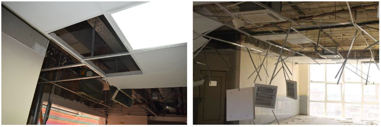
Suspended ceiling damage during 2017 Iran–Iraq earthquake; Left: west Eslam Abad hospital; Right: Payam Noor University at Sarpol Zahab district.
During the past three decades, various experimental projects (ANCO, 1983; Badillo-Almaraz et al., 2007; Blasi et al., 2018, 2021; Brandolese et al., 2019; Fiorin et al., 2021; Gilani et al., 2013; Jenkins et al., 2017; Ju and Gupta, 2015; Rahmanishamsi et al., 2014; Ryu and Reinhorn, 2013; Soroushian et al., 2012, 2016c; Tadinada and Gupta, 2017; Tian et al., 2014; Zaghi et al., 2012; Zhou et al., 2021) and multiple numerical works (Echevarria et al., 2012; Fiorin et al., 2021; Perrone et al., 2020; Ryu and Reinhorn, 2017; Soroushian et al., 2014c, 2015D; Tian et al., 2015; Zaghi et al., 2016) were performed on CP systems. However, because of the complexity of these two systems, previous numerical studies were found to be less reliable compared to full-scale experiments. As result, most of the standards, guidelines, and software such as ASCE7-16 (American Society of Civil Engineers, 2016), FEMA P-58 (Federal Emergency Management Agency, 2014), and Performance Assessment Calculation Tool (2016) are completely based on previous historical and experimental observations. While physical observations have their own merits, the limited number of design variables, higher associated expenses, and geometry limitations are inherent drawbacks of these types of data. Therefore, an experimental-based modeling methodology that reliably estimates the seismic behavior of CP systems is a critical step, which is the main intention of this article.
In this article, the design requirements of both suspended CP systems are described. Then, a brief description of previously developed nonlinear models that are used in the presented modeling methodology, is discussed for both piping and ceiling components. These models were incorporated in Open System for Earthquake Engineering Simulation (OpenSees, 2021) software based upon the outcomes of the experimental test results. In addition, the experimental setup of a CP assembly tested in the Soroushian et al. (2012) research is defined. The test subject was built in full scale containing five stories configuration. Afterward, the detail of the derivation of floor motions, which were the inputs for the CP model as well, is explained. Finally, the accuracy of the proposed model was examined through the comparison of CP response and collapse pattern in the suspended ceiling with those from the experiments.
Suspended ceiling systems
Suspended ceiling systems are architectural parts of a building installed to cover the electrical and mechanical instruments under the structural ceiling and gives a modern look to space below. These systems generally consist of an inverted tee (±) grid system, supporting elements, and ceiling panels. To form a grid plane, main runners and 2 ft cross tees are placed parallel to each other, and the 4 ft cross tees are set in the perpendicular direction. Ceiling grid latches are used at the intersection of the tee beams and the ceiling perimeter due to the grid duty level. Ceiling panels simply rely on the flanges of the beams filling empty spaces of the grid system. These tiles are available in different shapes and sizes. In a suspended ceiling, hanger wires transferred the deadweight of the entire system to the structural ceiling. These wires are placed with a clearance of 8 inches from the wall and then with a 4 ft clearance from each other. The wires are placed on the main runners. Light gauged L-shaped wall angles also provide a sitting area for the grid tees at the edge of the ceiling. All steel angles are screwed to the perimeter walls using a specified connection.
In the low seismic zones where no bracing systems are required, the ceilings can freely float within their boundaries. In this condition, a clearance of 3/8-inch should be provided between the ceiling and perimeter walls. In regions with a high risk of seismic activities, two of the adjacent edges are fixed to the surrounding walls and a 3/4-inch clearance is provided for the other two edges between the wall and the ceiling system. In this condition, a vertical compression post along with four 45-degree splay wires are set to resist against the lateral forces. The compression post provides resistance against the vertical component of the splay wires. This bracing section is added on the main runners at a 12 ft clearance from each other starting at the point of 6 ft from the partition walls. Figure 2 indicates a schematic view of a seismically braced suspended ceiling system.
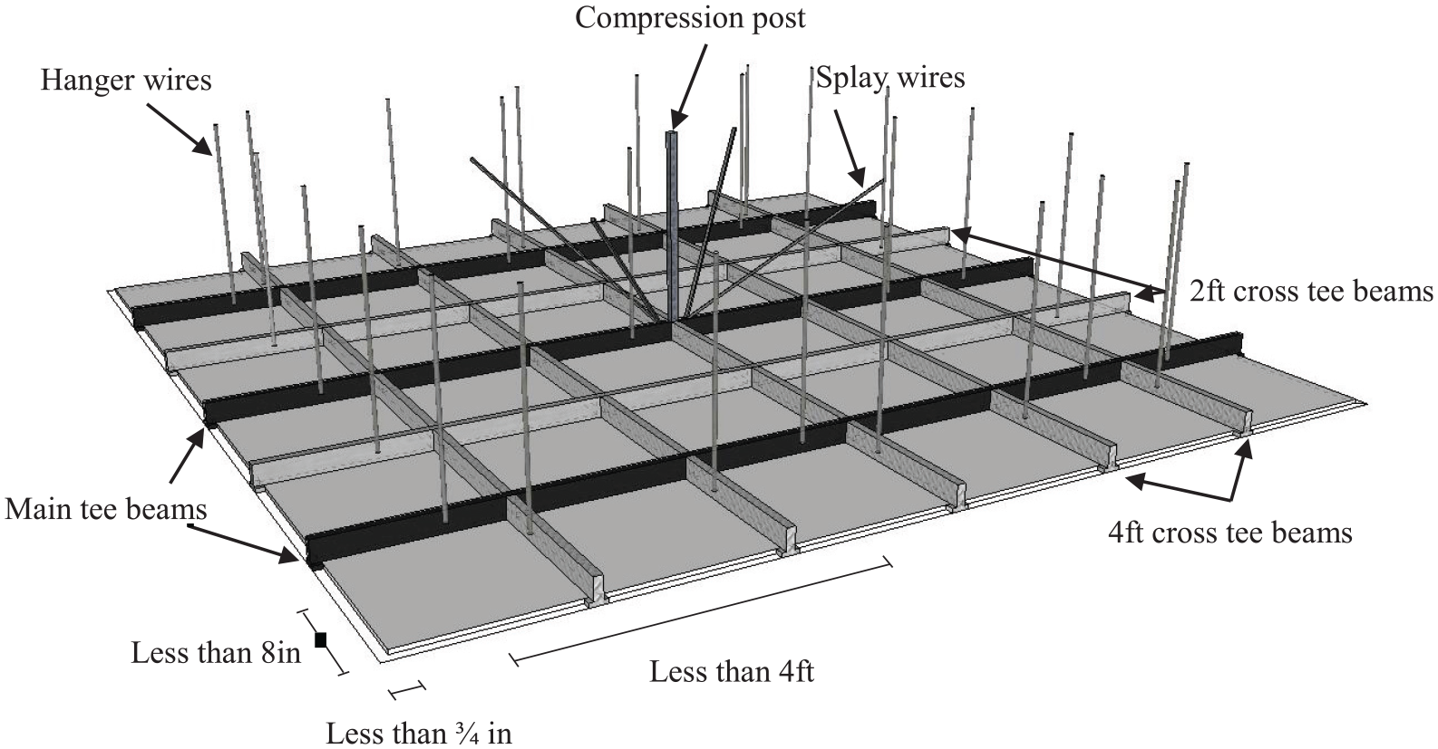
Schematic view of suspended ceiling system.
Fire sprinkler piping systems
A fire sprinkler system is generally consisting of pipe runs, sprinkler heads, supporting elements, and a water supplier. The water pressure tank provides the required pressure to relocate water and spray it through the sprinkler heads during a fire or smoke. Pipe runs include vertical risers, main runs supplying branch lines, and branch lines that supply drops. Piping drops that are manufactured in straight and armover types then feed the sprinkler heads. In a fire sprinkler piping system, threaded hangers transfer the gravitational weight of the system while the seismic braces react against the lateral loads during earthquakes. The bracing system of a fire sprinkler piping unit can be a solid rod or a cable (tension-only) element. Wire restrainers also lower the side movements of branch lines. A detailed view of typical fire sprinkler piping components is shown in Figure 3.
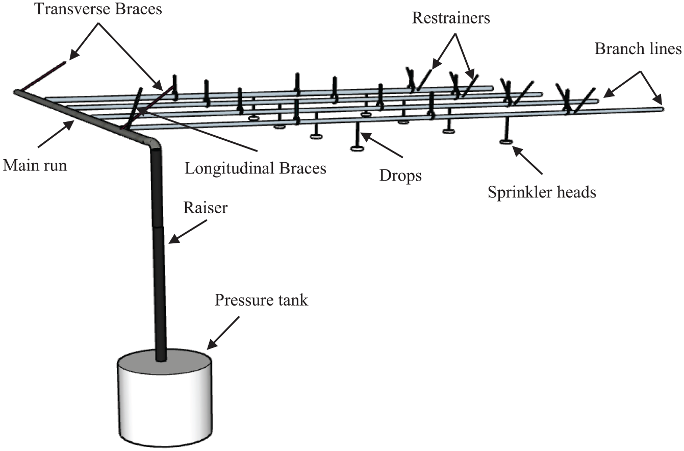
Schematic view of fire sprinkler piping system.
Benchmark experiment
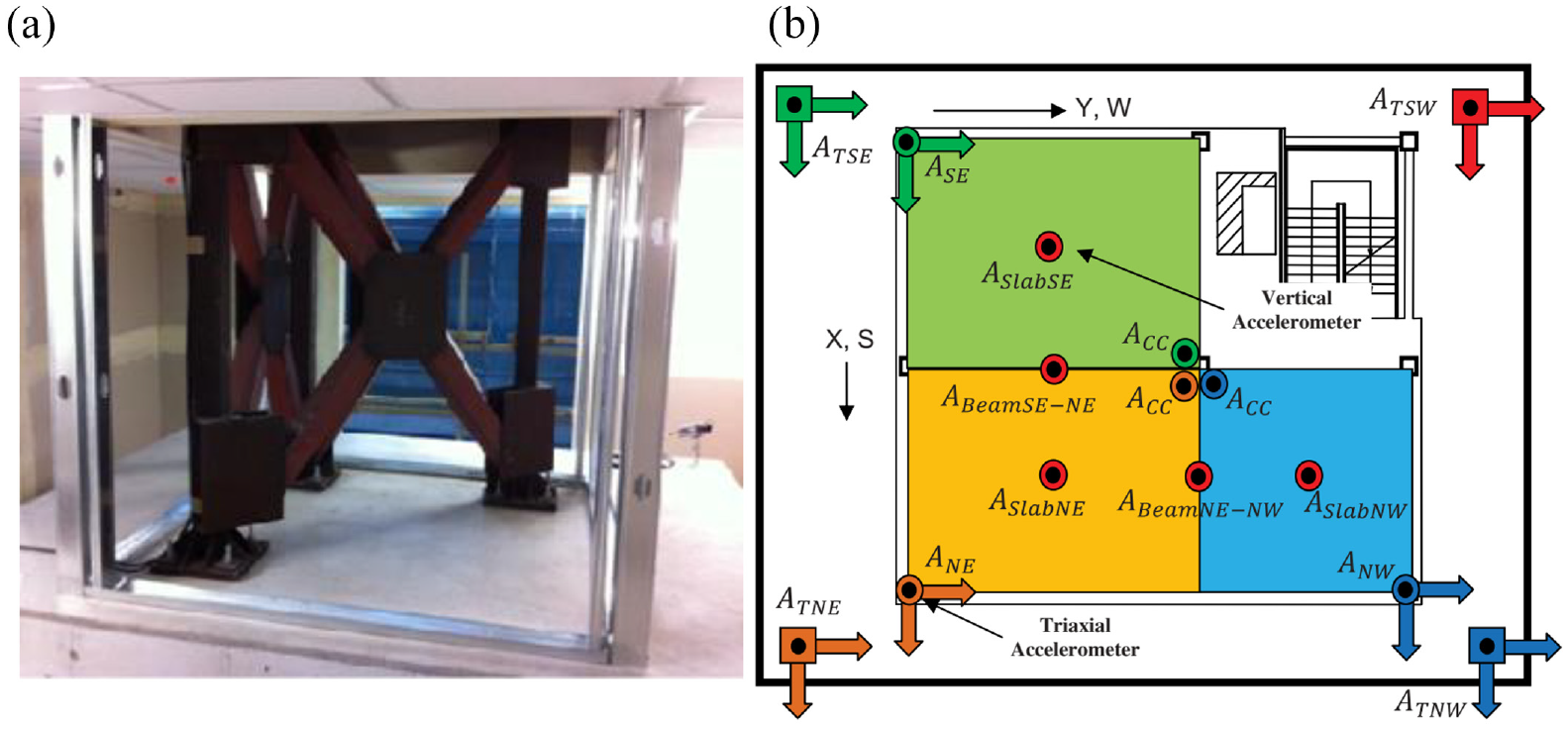
The seismic behavior of nonstructural systems was tested during a moment frame five-story structure built through a joint project. The project was conducted between George Brown Jr. Network for Earthquake Engineering Simulation (NEES) program and the National Science Foundation (NSF) from the United States and the National Institute of Earth Science and Disaster Prevention (NIED) of Japan. The interaction partition-ceiling-sprinkler unit was set at the fifth and roof levels of the structure designed in braced and unbraced configurations. This structure was built fully scaled with the height of 53 ft and asymmetric in the plane with dimensions of 33 ft by 40 ft (see Figure 4). Throughout the test program, this building had three base conditions as (1) isolated with triple friction pendulum bearings, (2) isolated with the combinations of elastomeric bearings and cross linear sliders, and (3) fixed base. In this article, the results of the fixed base building under two extreme three-dimensional earthquake simulations will be used and presented in the following sections. Readers can find further information about the structure specimen in the studies by Dao (2012) and Ryan et al. (2013d).
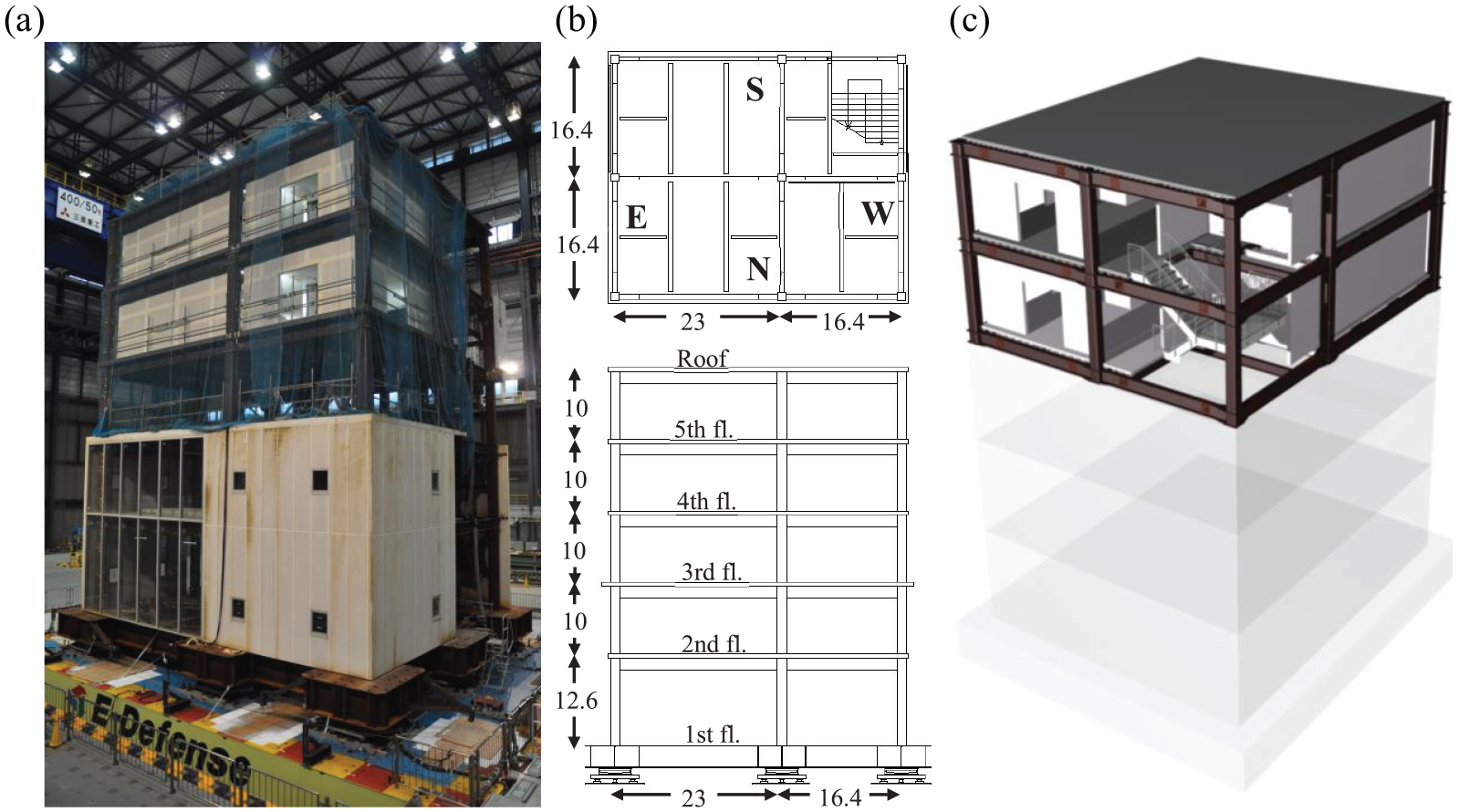
(a) View of the building specimen, (b) overall dimension (in ft.) of building specimen, (c) floors containing nonstructural systems including ceiling and fire sprinkler piping systems (Soroushian et al., 2012).
The fire sprinkler piping system designed for this project consists of a riser pipe with a 3-inch diameter connected to a 2.5-inch diameter main run, which supports three 1.25-inch and 1-inch diameter branch lines in the ceiling plane. The main run and branch lines were installed through East–West and North–South directions, respectively (see Figure 4). It should be mentioned that for all pipes of the system, standard weight pipes (Schedule-40) in NFPA13 (2011) were used. Grooved fit connections and threaded joints were designed to connect components of the piping system. At the location of the riser connecting with the main run, and also for the main run connecting to the branch lines, grooved fitting joints were used. For all other attachments, threaded joints were set. In this project, armover drops and straight drops were installed on Branch Line 1, and Branch Line 2, respectively. Each of the branch lines was feeding three 12-inch sprinkler heads (Figure 5a). However, for second drop on the third branch line, a Victaulic Aquaflex flexible hose drop was used (Victaulic, 2008). The side movements of all branch lines were limited using two diagonal 12-gauge splay wires at both ends. Inclined 1-inch diameter pipes were also providing additional in-plane support for longitudinal and transverse direction on the main run near the riser. In this configuration, a transverse solid brace was located at the end of the main run. Two solid braces were also put at the end of the riser pipe below the fourth floor.
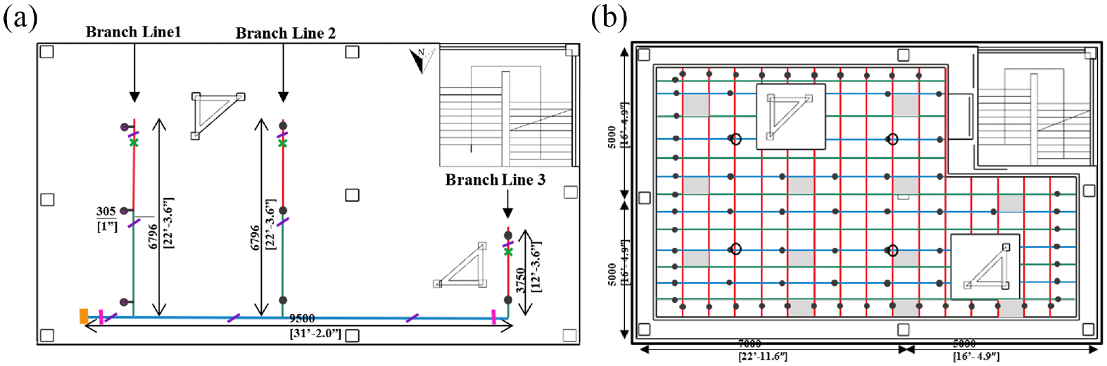
Plan view of (a) fire sprinkler piping system and (b) suspended ceiling system. (Soroushian et al., 2016c).
The ceiling was designed using common lay-in-tiles and with an area of approximately 900-ft2 (Figure 5b). The ceilings on both floors were designed and constructed in the test frame according to the provisions of American Society for Testing and Materials (ASTM, 2011) E580/E580M-11ae1 standards. The grid tee beams were fabricated for heavy-duty loads using the USG DONN 15/16 inch exposed tees. Both ceilings were suspended by 12-gauge Hilti X-CW wires placed at 4 ft intervals from each other on the main runs, and 8-inch clearance from the perimeter partition walls. The distance between the structural slab and the suspended ceiling grid (called the Plenum Height) was set at 3 ft. Wall moldings were also attached to the perimeter walls leaving a 7/8-inch clearance.
In this project, the North and East perimeters of the ceiling were fixed boundaries, and the South and West sides were designed to float freely. The fixed boundaries of the ceiling were built using USG/ACM7 seismic clip attachments with one top-hole screw and one partition-attached screw. The floating edges are also designed using the same seismic clips. In this case, however, the second screw is attached at the middle of the clip slot leaving a 3/4-inch clearance with the perimeter walls. On the suspended ceiling systems, the ceiling lights were accounted for in the modeling by adding extra weight (heavier tiles) to the corresponding panels. These panels are indicated as hatched areas in Figure 5b. To investigate the impact of the bracing systems on the dynamic response of suspended ceiling systems, a USG/VSA30/40 compression post and a system of splay wires were installed on the fifth floor of the structure. All other design properties of both ceilings were set equally on both floors. The splayed wires were attached to the main run within a 2-inch distance from the compression post at the specified locations. To provide the connection constraint, a steel compression post was used instead of the VSA30/40 at the locations where compression posts were attached to the structural girders. For the space constraint also, two of the splay wires on each floor were replaced by rigid braces of two-way steel rods. The CP system was interacting with each other at the location of sprinkler heads (beneath the drop locations shown in Figure 5b).
Modeling methodology
As part of the long-term plan of the NEESR-GC nonstructural project, more than 200 component-level tests were applied on a CP system. Based on the results of this project, simulation methodologies have been developed at the component-level scale and verified with both suspended CP response. The modeling and its validation are detailed in the study by Soroushian et al. (2014c, 2015a, 2015b, 2015c, 2015d, 2016b). In this article, these component-level simulations are adapted to generate and develop a more comprehensive model, which can capture the seismic response, failure types, and the interacting response of the CP system. All physical characteristics of the components are assigned according to the measurements done during the experiments (Soroushian et al., 2015a). These values are obtained by capturing the force–displacement response and defining the hysteresis behavior of ceiling components in axial, flexural, and shear directions. A complete explanation on the test setups can be found in the study by Soroushian et al. (2015a).
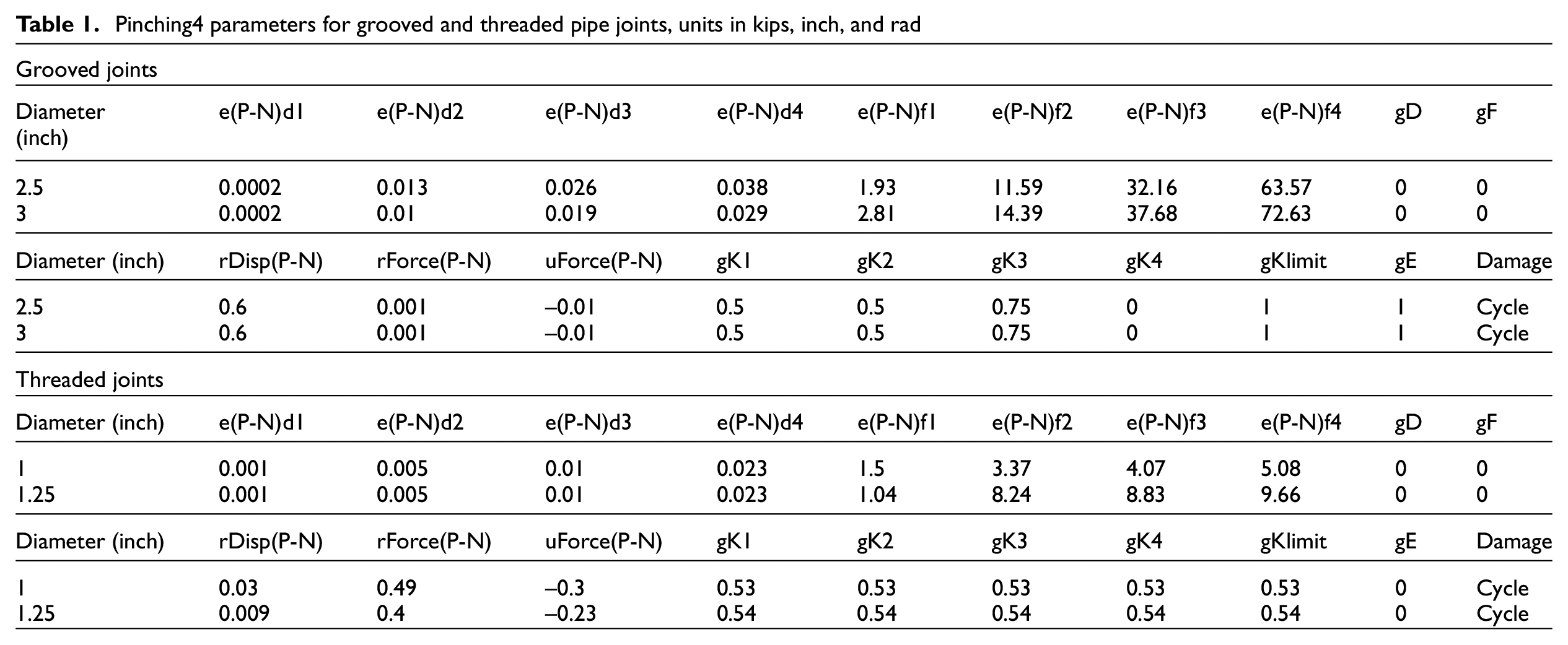
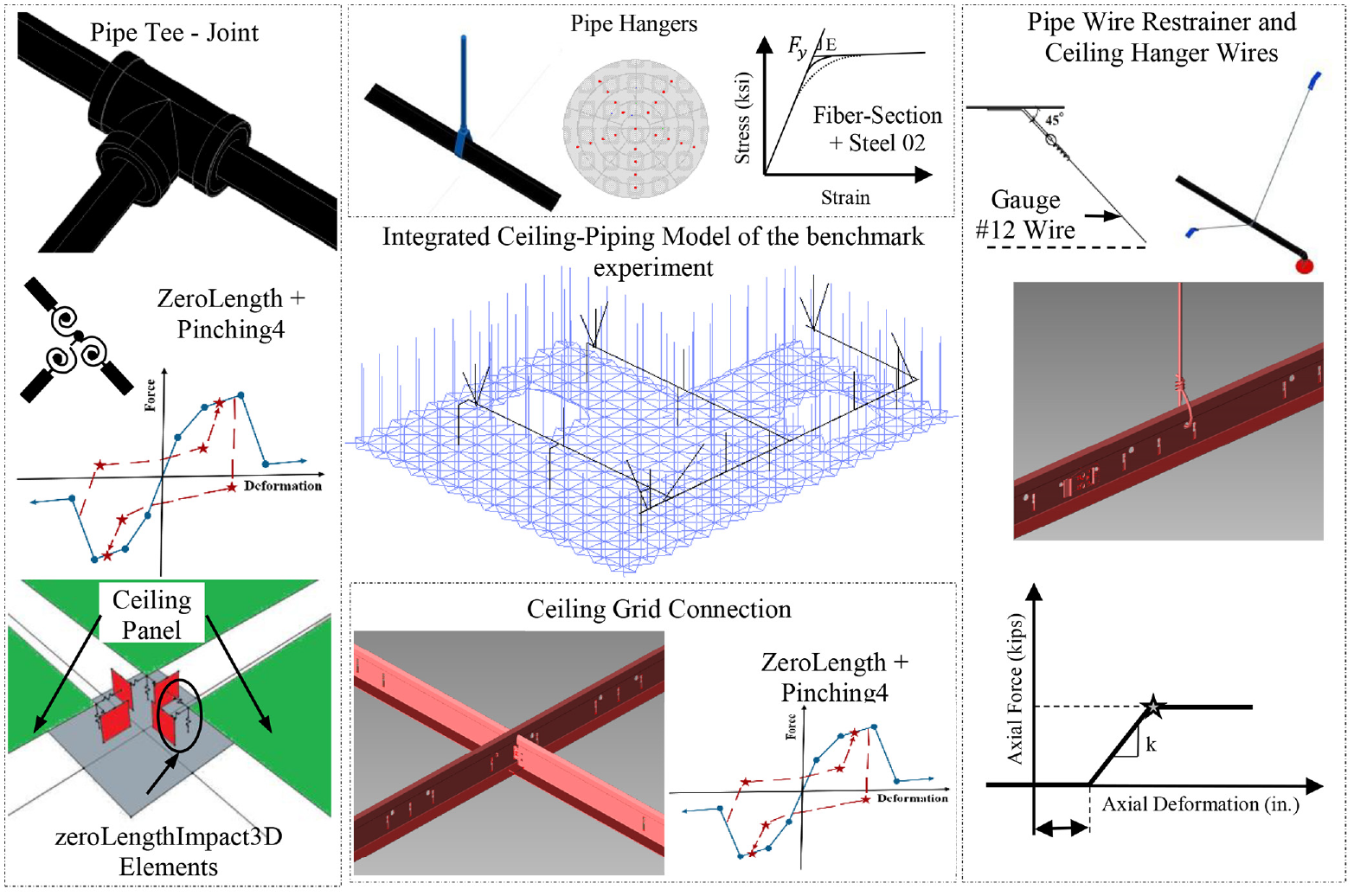
OpenSees software is used in the generation of all the proposed models (OpenSees, 2021). Pipe runs are simulated by the “Force-Based Beam-Column” command (OpenSees, 2021) using the gross section properties of the pipes. Two moment-rotation inelastic models were assigned to the rotational degrees of freedom to simulate threaded joints and grooved fit connections of the piping system at the defined locations. The “Pinching4” material in the OpenSees software is used for the generation of these models (OpenSees, 2021). This material model considers the pinched behavior and strength degradation of piping joints under each loading cycle. Thirty-nine parameters are required for the definition of a “Pinching4” material, including the shape of the backbone curve, pinching parameters, damage parameters, and so on (see Figure 6)(OpenSees, 2021). The main parameters (in Positive (P) and Negative (N) directions) of this material used in this study are: (1) response envelope points (e(N/P)di, e(N/P)fi), (2) reloading/maximum historic deformation ratio (rDisp(N/P)), (3) reloading/maximum historic force ratio (rForce(N/P)), (4) positive (negative) unloading/minimum (maximum) monotonic strength ratio (uForceN(P)), and (5) ratios defining the unloading stiffness degradation (gKi). These values are presented in Table 1 for each pipe diameter. The hanger rods were modeled using nonlinear “Force-Based Beam-Column” (OpenSees, 2021) elements with a 48-fiber section consisting of the Giuffre–Menegotto–Pinto steel material (Comite Euro-International du Beton, 1996). Multiple physical properties are required to define the hanger rods, which include (1) a modulus of elasticity (E = 21,600 ksi), (2) yield strength (Y =64 ksi), and (3) a hardening slope ratio (S = 0.01%). These rods are connected to the pipe runners at one end and are fixed at their other ends. The restrainer wires are simulated using “truss” elements with a tension-only material in the OpenSees software known as the “Elastic-Perfectly Plastic (EPP) Gap” command (OpenSees, 2021). To define this, material modulus of elasticity and tensile strength is required. These values were set at 29,000 and 100 ksi, respectively. The elastic “Force-Based Beam-Column” elements are also used to model the rigid seismic bracing system, assuming a rigid behavior at both ends. The mass of the entire piping system is assigned as a lumped mass concentrated on the defined nods. These values include the mass of wet pipe runs and an additional 0.5 lb for each sprinkler head.
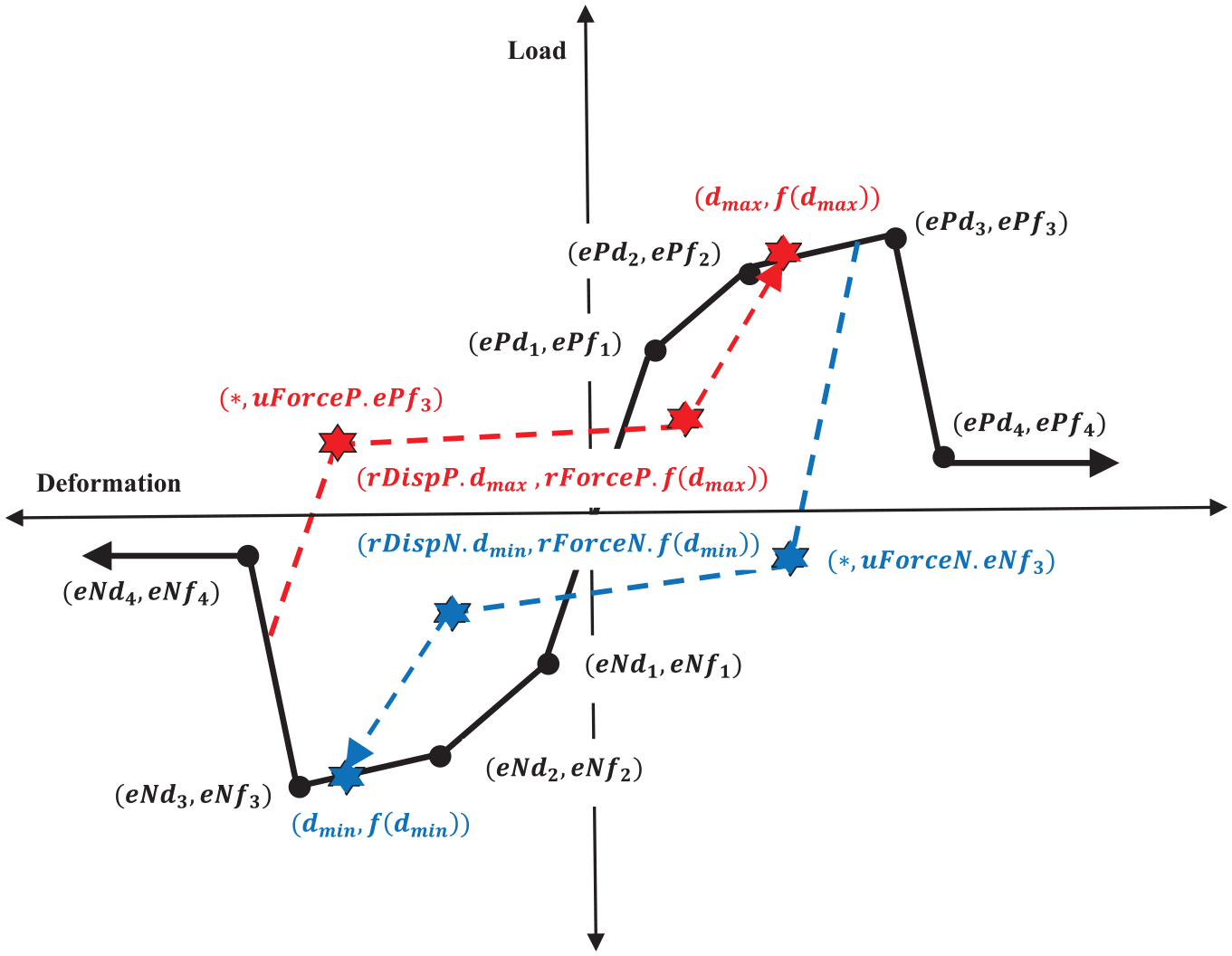
Thirty-nine parameters of Pinching4 material model.
Pinching4 parameters for grooved and threaded pipe joints, units in kips, inch, and rad
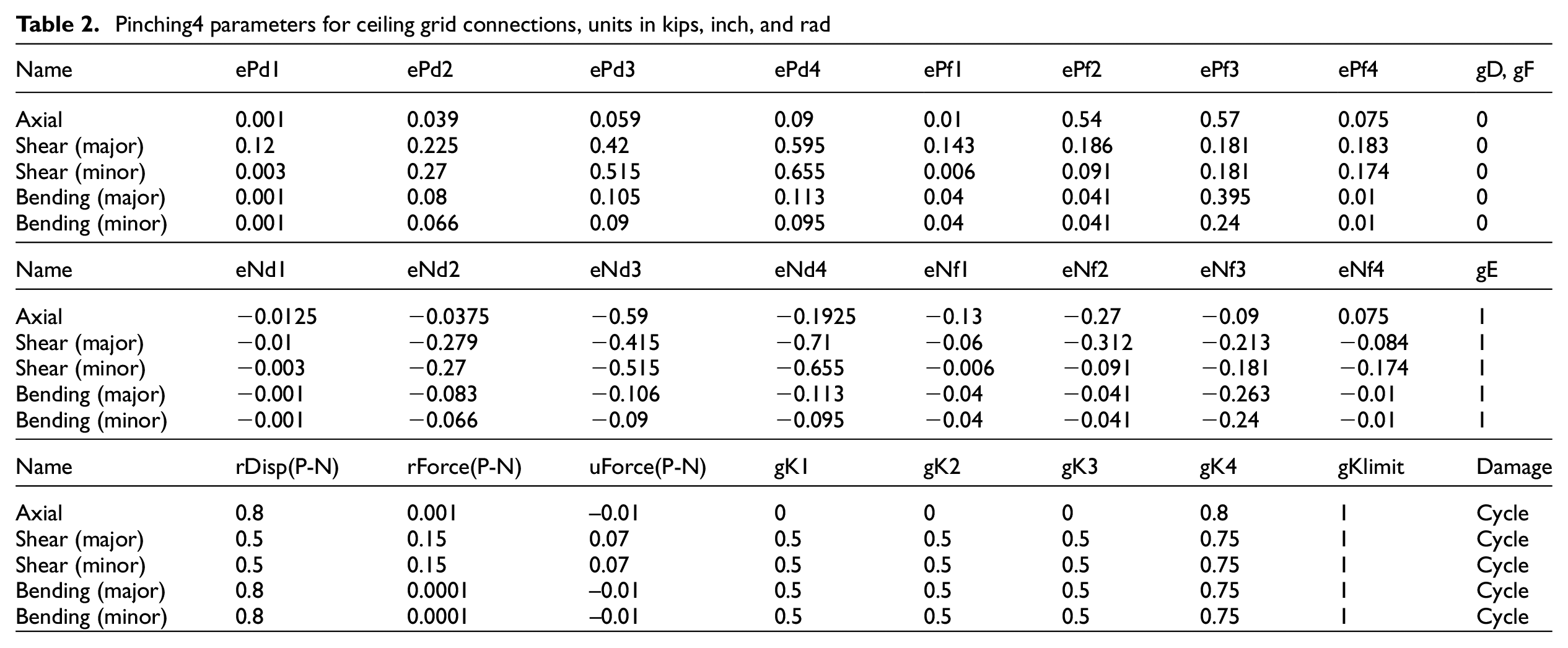
All ceiling grid tees are modeled using the elastic “Force-Based Beam-Column” command (OpenSees, 2021). The physical characteristics of real tee beams were assigned in their simulation process. The main tees of the grid system are assumed to be continuous. However, at the interaction point of the cross-tee elements, inelastic axial, shear, and bending models are defined using “zeroLength” elements and “Pinching4” material. The associated parameters of the “Pinching4” material model of cross-tee connections are presented in Table 2.
Pinching4 parameters for ceiling grid connections, units in kips, inch, and rad
The integrated “zeroLength” element and “Pinching4” material are also used at the fixed perimeter of the grid system. The “Pinching4” material parameters at the ceiling perimeters are presented in Table 3. At the floating boundaries, a horizontal “zeroLengthImpact3D” element is assigned with a 3/4-inch gap. These elements are capable of simulating the effects of impact, pounding, and friction (OpenSees, 2021) at the unattached perimeters.
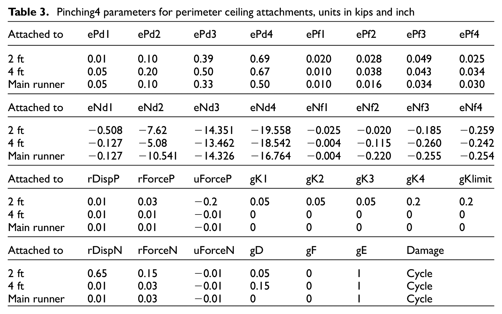
Pinching4 parameters for perimeter ceiling attachments, units in kips and inch
The ceiling panels are simulated as an X shape assembly (Zaghi et al., 2016). The weight of these panels is assigned on the corners of the X shape component and the middle point. The total deadweight of each panel is considered as 0.72 psf. Ceiling hanger wires and also the splay wires of the bracing system were modeled similarly to the pipe restrainers. The compression post is also modeled using the elastic “Force-Based Beam-Column” (OpenSees, 2021) elements with the physical properties of a real system.
Three “zeroLengthImpact3D” are assigned between the corners of the panel and the grid tee intersection. The two horizontal springs with the 1.25-inch gap can capture the related movements of panels toward the grid system. The vertical spring, however, records the displacement in the vertical direction accounting for the uplift and pounding of the panels. This element has an initial gap of zero representing the lay-in tiles. An additional “zeroLength” element were defined at the same locations, to record the panel–grid interaction in the vertical direction. The “Elastic” uniaxial material is also assigned to this element. According to the experimental data, a stiffness value of 2-lb/inch is assigned to the ceiling panels. However, on the perimeter panels, a higher stiffness was observed due to the additional resistance of seismic clips and hanger wires. A stiffness value of 4-lb/inch were assigned for these panels (Soroushian et al., 2015a). For the “zeroLength” elements also, an in-plane friction coefficient of 0.5 was considered throughout the modeling.
The interaction of the CP system is simulated using two in-plane “zeroLength” elements between sprinkler head nodes and the node representing the panel center. Two inelastic force–displacement material models in the positive and negative direction (representing tension and compression forces, respectively) are assigned to every “zeroLength” element. These inelastic models utilized the “Elastic-Perfectly Plastic (EPP) Gap” material and are parallel to each other. The initial gap of oversized holes is assigned using this material model considering their various dimensions. Along with the various spacings, a tensile and compressive strength of ±0.06-ksi and a modulus of elasticity of 0.36-ksi is assigned to the EPP material model. An overview of the integrated modeling methodology is illustrated in Figure 7. It should be also noted that Rayleigh damping with a 7% damping ratio set to the first and third modes of the integrated system, which was obtained from the experimental system identification study by Soroushian et al. (2014b).
Overview of modeling methodology used for the benchmark experiment (Soroushian et al., 2015b).
To capture the damage portion and failure mechanism of the suspended ceiling and piping system, removal algorithm was developed at each time step of the analysis. The element removal algorithm makes the numerical model capable of redistributing stiffness and forces (as a result) after each component failure using the “remove element” command in OpenSees (2021). An ultimate failure value (displacement or force) is assigned to each element of the suspended ceiling and piping system. At each time step, the numerical model compares the demands generated in the components with their ultimate criteria. Using this command, every element reaching its maximum capacity will be removed from the model and the analysis continues. These criteria are set according to the results of previous capacity evaluation experiments. The piping restrainers are removed by this algorithm when they reach their maximum capacity of 0.4 kips from USG Corporation (2006). Pipe hangers are also removed during the history analysis when their axial forces exceed five times the recorded axial force plus 250 lb (NFPA13, 2011). The ultimate strength of solid braces is 6.3 kips (NFPA13, 2011). Every solid brace reaching this criterion are removed from the numerical model using the removal algorithm.
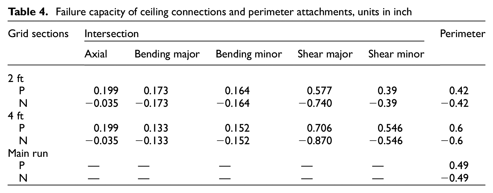
The failure criteria for suspended ceiling components are presented in Table 4. The ceiling hanger wires and bracing components are removed when their axial forces at every iteration of the analysis exceed 90 and 250 lb (ASTM, 2011), respectively.
Failure capacity of ceiling connections and perimeter attachments, units in inch
The ceiling panels were also subjected to removals during the analysis. This occurs when the displacement of the corner of the panels fills the initial gap between the panel and the grid system as long as the uplift of the panel exceeds the grid tee elevation (see Figure 8a). Ceiling panels also fail during the analysis due to the failure of the grid tee beams. When two connections of a 2 ft cross-tee fails (reaching their ultimate criteria), the component, corresponding attachments, and two panels on its both sides are removed (see Figure 8b). When a 4 ft cross-tee fails, however, two 2 ft tees and four panels on both sides are removed from the model (see Figure 8c).
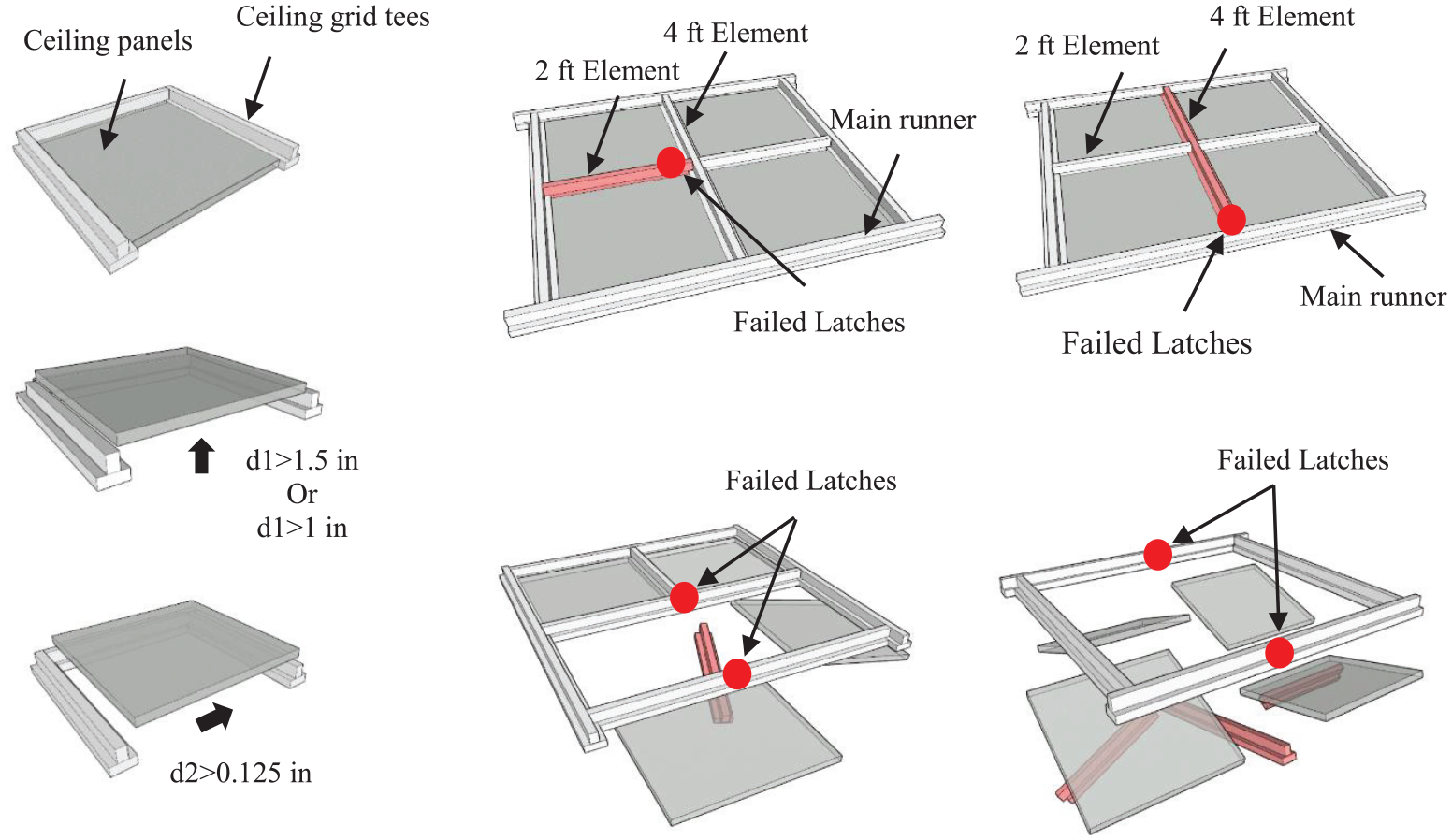
Remove element failure mechanisms. (a) Panels uplift, (b) 2 ft cross-tee failure, and (c) 4 ft cross-tee failure.
Input motion
The input motions used for validation purposes were obtained from the previously mentioned experiment. Through this experimental program, the five-story structure was subjected to multiple seismic records in 6 days. The sample structure, which is used as the validation source for this numerical model, was constructed with three various base configurations including (a) the triple pendulum isolated configuration (TPB), (b) the lead rubber isolated configuration (LRB-CLB), and (c) fixed-base configuration. Since the horizontal component of excitations will be significantly filtered out by using isolation systems, only the fixed-based phase of these test programs was used here. Five shaking table excitations out of 41 were used to examine the fixed-base condition. In three of them, triaxial input motions were applied on the structure including a vertical component, and in the remaining tests, only biaxial horizontal excitation was used. Since the seismic response of ceiling systems are sensitive to the vertical component of input excitation, CP system responses under three-dimensional (3D) excitation listed in Table 5 will be considered in this study.
Triaxial seismic input records
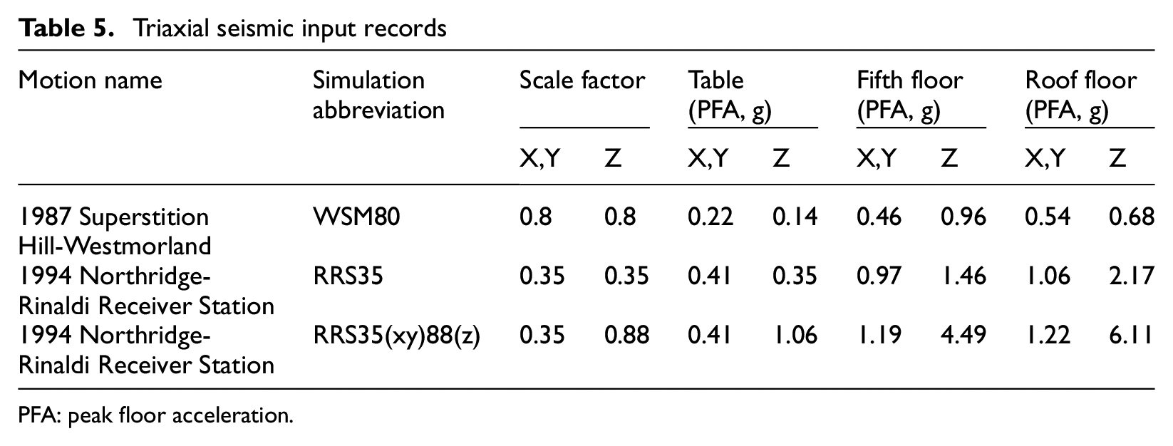
PFA: peak floor acceleration.
For the sake of nonlinear response history analysis, floor motions at the two top levels of the building were used as the input motion for the integrated CP system. Throughout this experiment, around 400 sensor channels recorded shake table and building responses at a sampling frequency of 1000 Hz. A four-pole low-pass Butterworth filter with a cutoff frequency of 25 Hz was applied to all recorded. Two drift measurement trusses at the N-W and S-E of the building are shown in Figure 9a. In addition, the layout of accelerometers on a typical floor is also shown in Figure 9b. It should be noted that in addition to triaxial sensors at the locations of columns, vertical accelerometers were set at the middle points. All of the data used in this project are archived at the NEES Project Warehouse and are publicly accessible (Ryan et al., 2013a, 2013b, 2013c; Soroushian et al., 2012). Examples of horizontal floor acceleration histories recorded at the fifth floor level under Superstition Hill-Westmorland (WSM80) and Northridge-Rinaldi (RRS35) with scale factors 80% and 35% are shown, respectively (see Figure 10) (Ryan et al., 2013a, 2013b, 2013c; Soroushian et al., 2012).
(a) Drift measurement truss and (b) typical layout of accelerometers at the floor levels.
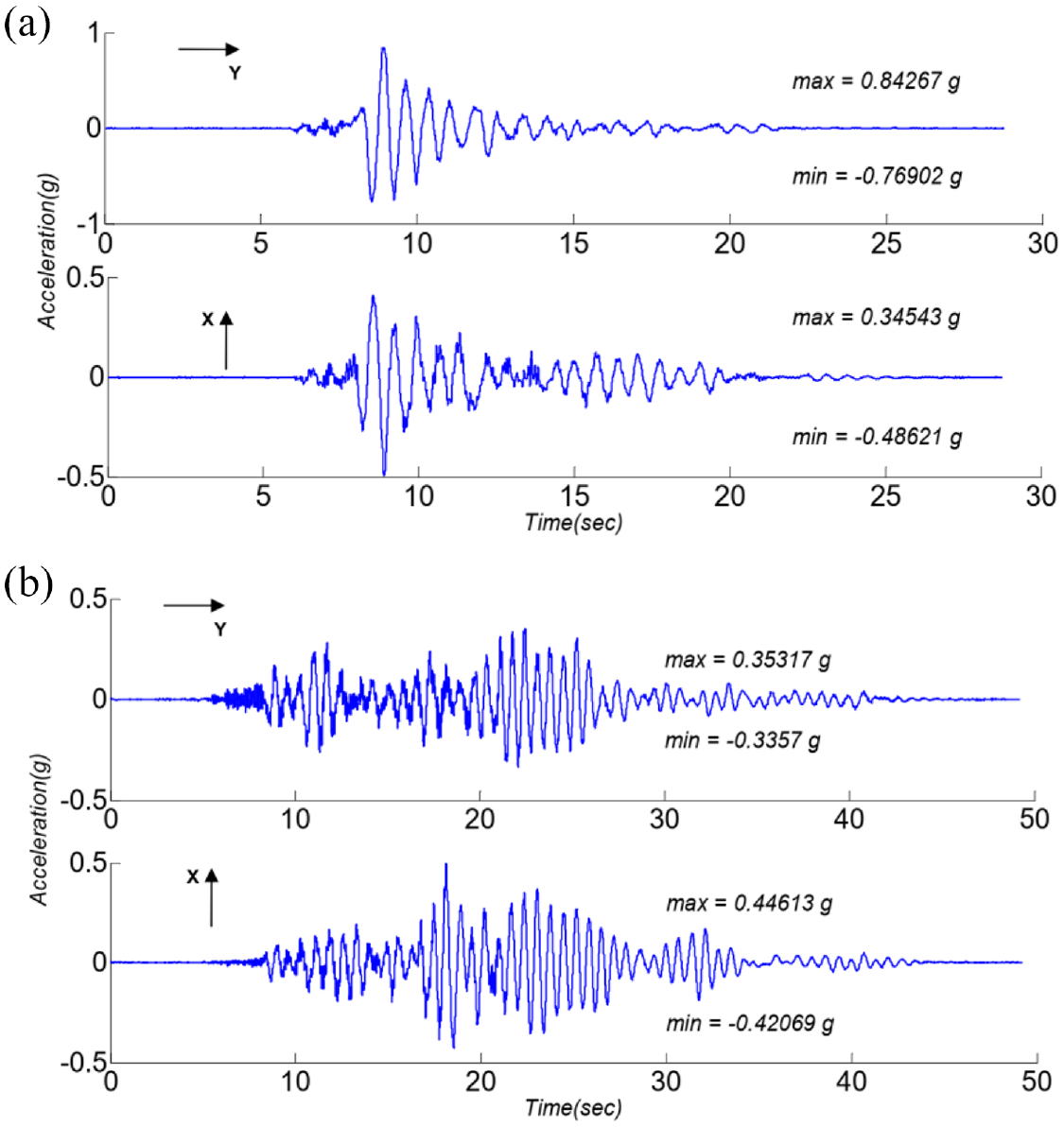
Calculated horizontal components of acceleration histories at geometric center of fifth floor: (a) under RRS35 and (b) under WSM80.
As mentioned earlier, the seismic response of suspended ceiling systems highly depends on vertical supporting floor excitation, which was significant in the referenced mentions used in this study (see peak floor acceleration (PFA) values in Table 5. As discussed in the study by Soroushian et al. (2012), the main source of large vertical acceleration was due to mounted additional weight on the east side of the roof, which caused excessive vertical slab vibration. Furthermore, the sensor data showed that the level slab vibration increased from the column locations toward the center of the slabs. Therefore, in order to accurately examine the seismic behavior of the CP system under this differential vertical movement, multiple support excitation was utilized using OpenSees (2021).
Since multiple support formulation in OpenSees (2021) requires input excitation in the form of displacement, horizontal and vertical floor displacement histories were derived as the input motion for nonstructural components. To do so, the horizontal displacement histories (X and Y) were calculated at the geometric center of the floors, which were taken as the sum of the (average) displacement readings through the floors from the two displacement trusses mounted on each floor. However, in the vertical direction, since there were no direct displacement sensors, a multi-resolution wavelet-based de-noising algorithm was used to convert acceleration floor records to the displacement ones. For the sake of completeness of this article, a brief discussion of this wavelet-based conversion method is added here. However, readers are encouraged to review the background documents presented in the study by Soroushian et al. (2016a).
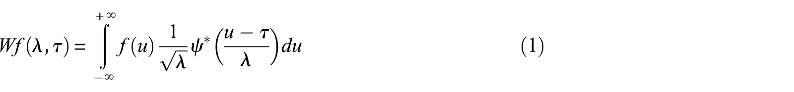
The procedure presented herein was applied to vertical recordings of all sensors (Ansari et al., 2007; Daubechies, 1992; Donoho, 1993, 1995; Donoho et al., 1995; Donoho and Johnstone, 1994; Noh et al., 2012; Taswell, 2000) mounted on fifth and roof floors. This methodology uses continuous wavelet transform (CWT) of a function
where
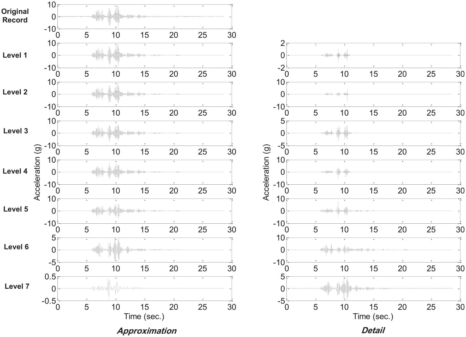
Wavelet multi-resolution decomposition of a middle deck acceleration during RRS35(xy)88(z) simulation.
The signals obtained from the real data cannot exist without noises (Taswell, 2000). More often, the original signals need to be filtered out of the noisy background records through data analysis, known as “de-noising.” In general, a non-parametric adaptive wavelet de-noising method is used in this study. In this method, the correction of the acceleration signals is done through a two-step procedure. In the first step, a wavelet transform is used to decompose the acceleration record into N levels. Note that the Nth detail of the signal should remain in the frequency range of interest. Then, two modification functions proposed by Donoho (1993, 1995; Donoho et al., 1995; Donoho and Johnstone, 1994) are used to modify the amplitude of the details of the signal when it is higher than the defined threshold. These functions depend on the positive parameter

In the first stage, level-dependent hard thresholding along with the SureShrink method was used to modify the signals. The SureShrink is a level-dependent thresholding method, which is based on the characteristics of each decomposed level. After thresholding, the corrected acceleration record is obtained by reconstructing the modified details and approximation. The high-frequency contents of the signal modify through this stage of the method. In the next stage, a similar approach with a minor alteration done for the low-frequency contents of the signal. The difference between the two stages include the following. (1) Modification is performed in the second stage for the velocity record. Velocity can be obtained by integrating modified acceleration retrieved from the first stage. (2) The velocity records of the second stage is decomposed in M levels with
Floor displacements at the sensor locations are then obtained from double integration of de-noised acceleration histories mentioned above. Left plots of Figure 12 shows displacement histories estimated based on the aforementioned approach in SlabNE. It should be noted that horizontal displacement generated based on the double integration method is only used for the validation process, and direct horizontal measures (discussed earlier) are used as the horizontal input motion of the nonstructural systems. In order to estimate floor vertical displacement at any nonstructural support (braces, hangers, and restrainers) attachment points, a polynomial surface fitting between sensor locations at each time step was used. An example of such a fitting, at the time step when the maximum vertical displacement at SlabNE occurred, is presented on the right plots of Figure 12.
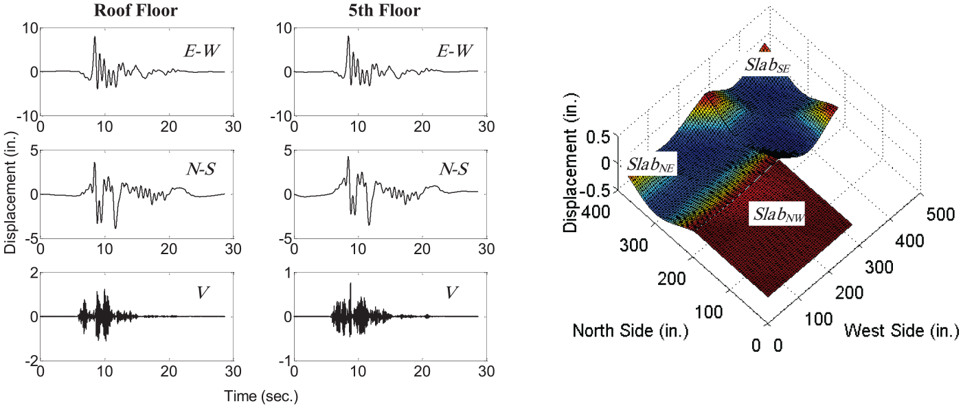
Estimated floor displacement during RRS35(xy)88(z) simulation.
Validation of numerical methodology
A brief discussion is presented in the following section to explain validity of the numerical model. The results obtained from the CP model is compared with the experimental data of the referenced tests. As reported in the study by Ryan et al. (2013b), a four-pole low-pass Butterworth filter with a cutoff frequency of 25 Hz was applied to all recorded responses. Therefore, the dominant frequency of the ceiling was not identified as it generally has a higher fundamental frequency. The fundamental periods of the piping system obtained from the numerical model and the experiments are presented in Table 6. The failure modes are also shown in Figure 13. Readers are encouraged to review the sensor locations and methodology that has been used to perform experimental system identification reported in the study by Soroushian (2013).
Natural periods of the piping system.

Failure modes of piping system: (a) main run, (b) branch line 1, and (c) branch line 2.
During the 35% RRS simulation, the displacement, acceleration, and 5% damped acceleration generated in the test specimen and the CP numerical model are compared and presented in Figure 14. These data are captured and presented at the same location. The approximate sensor locations are presented as plan-guide within each plot. As shown in this figure, the numerical model captured most of the major response details with some exceptions. Acceleration and displacement responses of the piping system were overestimated by the numerical model around 15% and 9%, respectively. Also, not every detail of ceiling displacement (toward the end of record history) was captured by the numerical model. However, since both ceiling and piping systems were partly displaced, replaced, and retrofitted during the previous base-isolated test series, some portion of prediction errors might be due to uncertain experimental conditions.
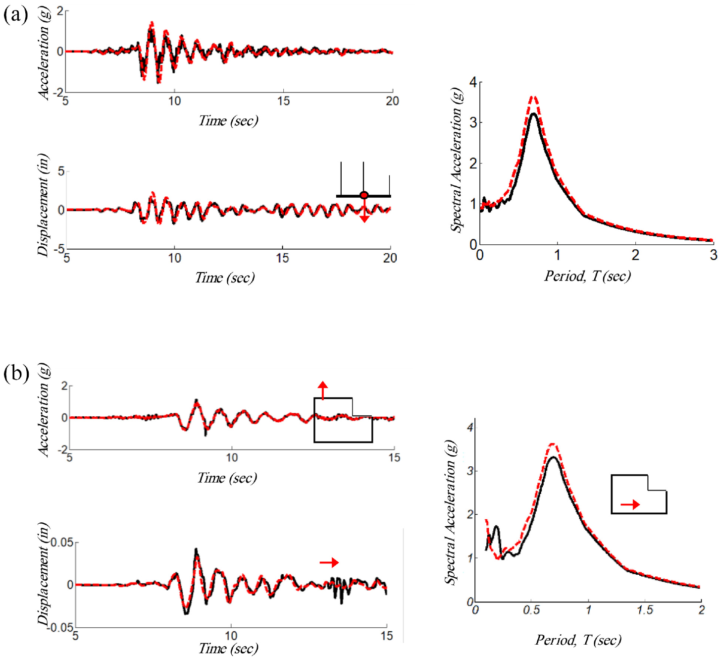
Validation of the numerical model (35% RRS): (a) fire sprinkler piping system and (b) suspended ceiling system.
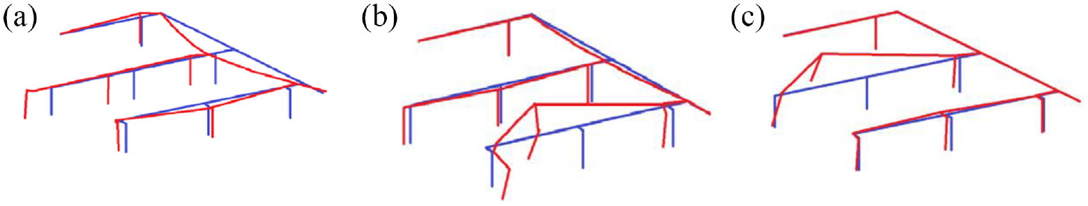
The end goal of this research was to generate an interacting ceiling model being able to capture the realistic damage propagation due to various damage mechanisms. Figure 15 shows the experimental and numerical damaged area of both braced and unbraced ceiling systems mounted below the roof and fifth floor levels. These plots show that the numerical model was fairly able to capture both damaged extent and locations. It should be noted the numerical model is incapable of detecting misaligned panels and only reports fallen or intact panels. Another difference that can be noted from this figure is that the extent of damage in the numerical pattern is larger compared to the experimental result. However, due to the complexity of ceiling dynamic behavior and its interaction with the piping system, such slight differences are anticipated.
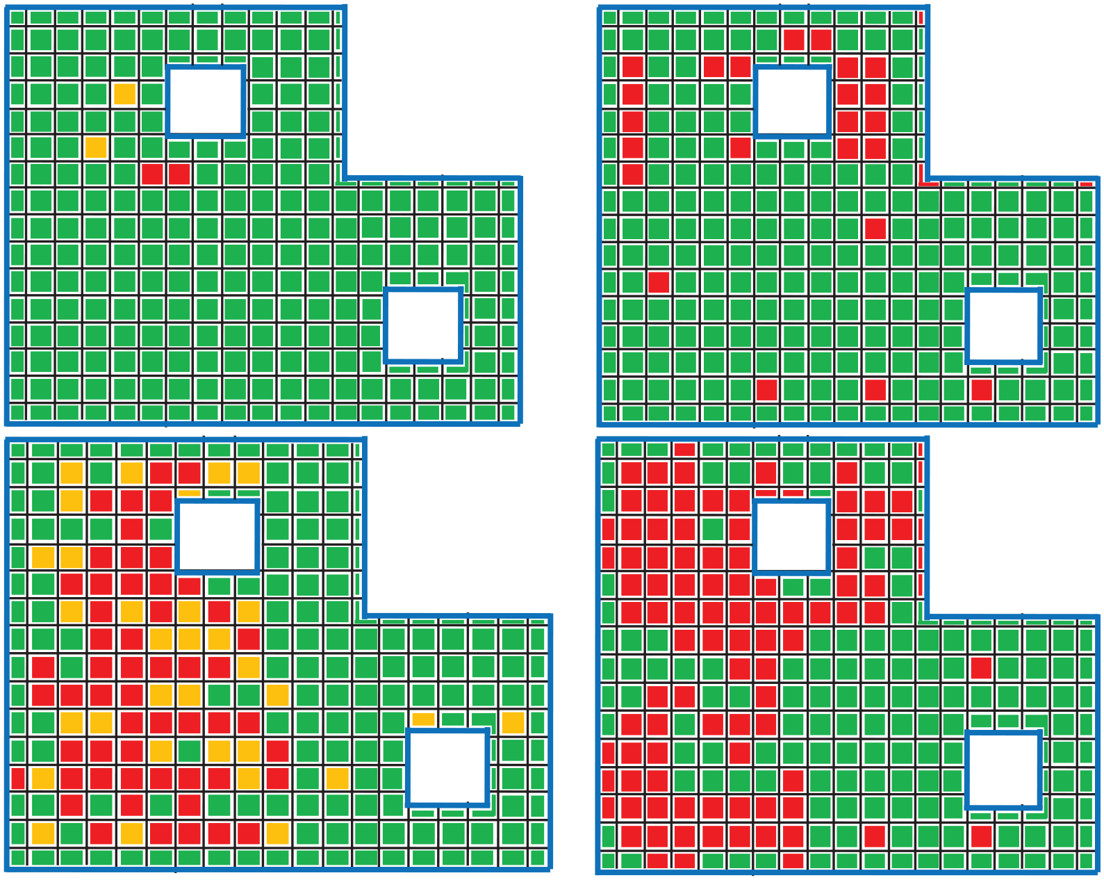
Pattern of fallen and misaligned ceiling panels.
These comparisons indicate that the behavior of braced suspended ceiling systems can be predicted more accurately with the proposed simulation method. Although the failure locations and failure portion of the unbraced ceiling match with the experimental observations, the difference is more noticeable with respect to the overall failure ratio of the system. The ceiling failure ratio is over estimated by the numerical model since the numerical model reports misaligned panels as fallen.
Summary and conclusion
In this article, the interaction between suspended ceiling systems and fire sprinklers was studied numerically using a novel modeling methodology. OpenSees (2021) software is used in the development of this numerical model. This methodology incorporated various previously developed experimentally validated component and subsystem level, numerical models. In the proposed numerical model, nonlinear behavior of connections and supporting members of both ceiling and piping connections were considered. The dynamic movement of ceiling panels relative to the grid system was simulated using various impact-based springs. Finally, several remove-element algorithms were coded for both ceiling and piping systems to capture progressive damage in both of these components.
The result of this simulation is validated using the results of an experimental program by NEES (United States) and NIED (Japan) in which, the seismic behavior of these systems in a full-scale five-story moment-frame structure was studied. This validation is achieved by comparing the system identification and response history results of CP systems between experimental results and numerical simulation. Toward the end, the failure patterns of the numerical model are compared against those observed during the experimental program. A comparison of the estimated numerical results and the results observed during experiments show good conformity; as such, the proposed model can be considered as a suitable tool for predicting the seismic behavior of these interacting CP systems.
Footnotes
Declaration of conflicting interests
The author(s) declared no potential conflicts of interest with respect to the research, authorship, and/or publication of this article.
Funding
The author(s) disclosed receipt of the following financial support for the research, authorship, and/or publication of this article: This material is based upon work supported by the National Science Foundation under grant no. 0721399. Any opinions, findings, conclusions, or recommendations expressed in this document are those of the investigators and do not necessarily reflect the views of the sponsors.