
Abstract
During recent major earthquakes, modern seismically designed buildings have demonstrated a low risk of collapse and life-safety limit states. However, both direct and indirect economic losses are often primarily due to damage to nonstructural components. This damage can be significant even under the more frequent low- or moderate-intensity earthquakes, as corroborated by system-level numerical studies, since it can result in greatly amplified forces and accelerations transmitted into the nonstructural components. Recent numerical research has demonstrated that this can be affordably and practically done by connecting the component to the structure via sacrificial controlled-strength steel fuses, designed to yield at desirable force levels and hence limiting the forces and damage in the nonstructural component. A shake table testing campaign was undertaken at the University of Bristol to experimentally validate this concept. The tests involved 14 specimens comprising different masses and tuned fuse geometries subjected to recorded floor motions, resulting in a total of 45 dynamic tests. The testing campaign, the instrumentation, the processing, and deduction of the response histories are described in detail. The resulting dataset is curated, organized, and made publicly available through an online repository to support further numerical and computational research on damage-free structures.
Keywords
Introduction
Recent earthquakes have demonstrated the vulnerability of nonstructural components even under low and moderate ground shaking where collapse and structural damage are not observed (Aslani and Miranda, 2005; Taghavi and Miranda, 2006). This can have a dire effect on the economy due to business interruption (Miranda, 2024; O’Reilly and Calvi, 2021). Notable examples are the cases of the Sylmar County Hospital in the aftermath of the 1994 Northridge earthquake (Naeim, 2004) and the Santiago and Concepcion airports during the 2010 Maule earthquake in Chile, which sustained very little structural damage but massive losses of nonstructural components (Fierro et al., 2011; Miranda et al., 2012). Similar observations have been made after recent earthquakes in New Zealand (Dhakal, 2010; Ferner et al., 2014).
With the advent of the performance-based design framework, several studies investigated the seismic response of buildings and the potential economic losses associated with structural and nonstructural damage (Elkady et al., 2020; Hwang and Lignos, 2017; Papadopoulos et al., 2019; Ramirez and Miranda, 2009; Taghavi and Miranda, 2006). These studies generally showed that for modern seismically designed buildings, nonstructural damage constitutes a major portion of the aggregated monetary losses, especially regarding acceleration-sensitive nonstructural components such as suspended ceilings, heating, ventilation, and air conditioning (HVAC) systems, and electric transformers data servers. Considering this issue and moving beyond the fundamental collapse prevention and life safety performance targets, the focus has shifted toward functional recovery (Cook et al., 2022; FEMA/NIST, 2021), particularly in community-critical buildings housing critical infrastructure or emergency services. This involves developing new strategies to minimize nonstructural damage.
It is well known that if a nonstructural component has a fundamental period equal or close to that of one of the prevailing modal periods of the supporting building, it can experience increased acceleration demands compared to those specified in the current seismic design provisions, for example, ASCE 7-22 (American Society of Civil Engineers (ASCE), 2022) and EN1998:2004 (CEN 2004). This has been shown numerically by using building models (Taghavi and Miranda, 2006; Wieser et al., 2013) as well as by using actual floor motions recorded during earthquakes in instrumented buildings (Kazantzi et al., 2020b). One way to avoid this issue and reduce the component acceleration demands is to allow some controlled inelasticity in the component’s supporting or bracing members (i.e. sacrificial fuses), as initially proposed by Miranda et al. (2018). The proposed approach combines key observations of the difference in demands between elastic and inelastic secondary systems tuned to the primary structure and well-known capacity-design principles within modern seismic codes. In their proposed approach, the nonlinearity is introduced in the attachments and can be achieved in various ways such as sliding, rocking, or yielding. The new approach provides several important benefits: (1) reduction of acceleration demands in nonstructural components; (2) dependable estimation (i.e. with reduced uncertainty) of forces to design the anchors to the structure and the nonstructural elements based on the capacity of the nonlinear attachments; (3) reduction in displacement demands for nonstructural components that are tuned or nearly tuned to modal modes of vibration of the primary (supporting) structure; and (4) reducing the design sensitivity to the ratio of the period of the nonstructural component to the period of the primary (supporting) structure.
A more accurate absolute acceleration demand assessment for inelastic nonstructural components is required for an effective design (Vukobratović and Fajfar, 2016, 2024). Kazantzi et al. (2020a, 2020b) further investigated this strategy numerically by examining the inelastic floor spectra for single-degree-of-freedom (SDoF) secondary systems representing the fuse-anchored nonstructural component. In their study, they assumed the SDoF response as a non-degrading bilinear hysteretic behavior with a post-yield-to-elastic stiffness ratio of 3%. This non-degrading response can represent a sliding element of a slightly concaved surface or that of the sacrificial yielding steel element (fuse) undergoing a stable hysteretic response. In this investigation, the latter approach was adopted. The fuse can be in the form of simple steel T-stubs or angles, as illustrated in Figure 1. Those are easy to design, install, and replace (if necessary), making them both practical and affordable. The study demonstrated the efficacy of the fuse concept where the computed inelastic floor spectra were substantially reduced (became flatter) with predictable force demands compared to their elastic counterparts, with the latter having narrow-band characteristics with strongly amplified resonance peaks.
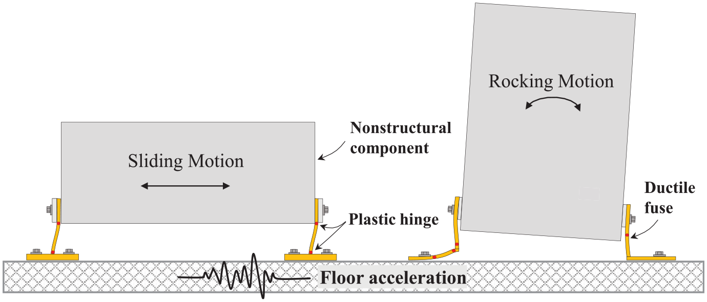
Illustration of the dominant response mechanisms of nonstructural components supported by sacrificial ductile yielding elements (fuses) under floor acceleration.
This article summarizes the details of an experimental campaign designed to corroborate the observations of the numerical study and reports on real shake table data that can support further research into this concept. The experimental campaign was conducted as part of the NSFUSE project that was undertaken at the EQUALS laboratory of the University of Bristol under the auspices of the EU-sponsored SERA Project, to investigate the conceptual validity of using ductile steel fuses for protecting acceleration-sensitive critical nonstructural components during earthquakes. The objective was to offer a reliable and inexpensive solution via replaceable sacrificial elements for the protection of critical nonstructural elements. The tests focused on nonstructural components whose seismic response is governed by horizontal movement (sliding), as demonstrated in Figure 1, rather than rocking. This can be implemented in many different types of nonstructural components with a low aspect ratio (height-to-width ratio) and low center of gravity.
Description of the experimental program
Test setup
The experimental program was conducted using the earthquake simulator (i.e. shake table) at the University of Bristol’s Earthquake and Large Structures (EQUALS) laboratory. The 3 m by 3 m shake table has a capacity of 15 tons and can reach acceleration up to 2 g with peak displacements of ±150 mm. This is sufficient to push the investigated structural steel fuses well into their nonlinear plastic range.
As previously mentioned, many nonstructural components can be idealized as SDoF systems with a defined mass and period. Since the experimental program aims to investigate specimens representing different nonstructural component properties, a modular test setup was developed for that purpose, as shown in Figure 2. Figure 2a shows a three-dimensional computer-aided design (CAD) model of the setup components, while Figure 2b shows the actual assembly in the lab. The setup comprises a fairly rigid U-shaped steel carriage supporting varying steel mass plates. The base of the carriage rests on two machined cylindrical steel rollers. The rollers, which possess very low rolling friction coefficients, can move horizontally in the X-direction, on top of two aluminum tracks. Four L-shaped guide sliders are installed on the lower end of both carriage walls to restrain the carriage from moving in the Y-direction and uplifting during shaking. To reduce friction between the different components, tolerances were designed and monitored carefully during construction and testing. The carriage walls have slotted holes at different elevations to accommodate the connection to structural fuses of different heights.
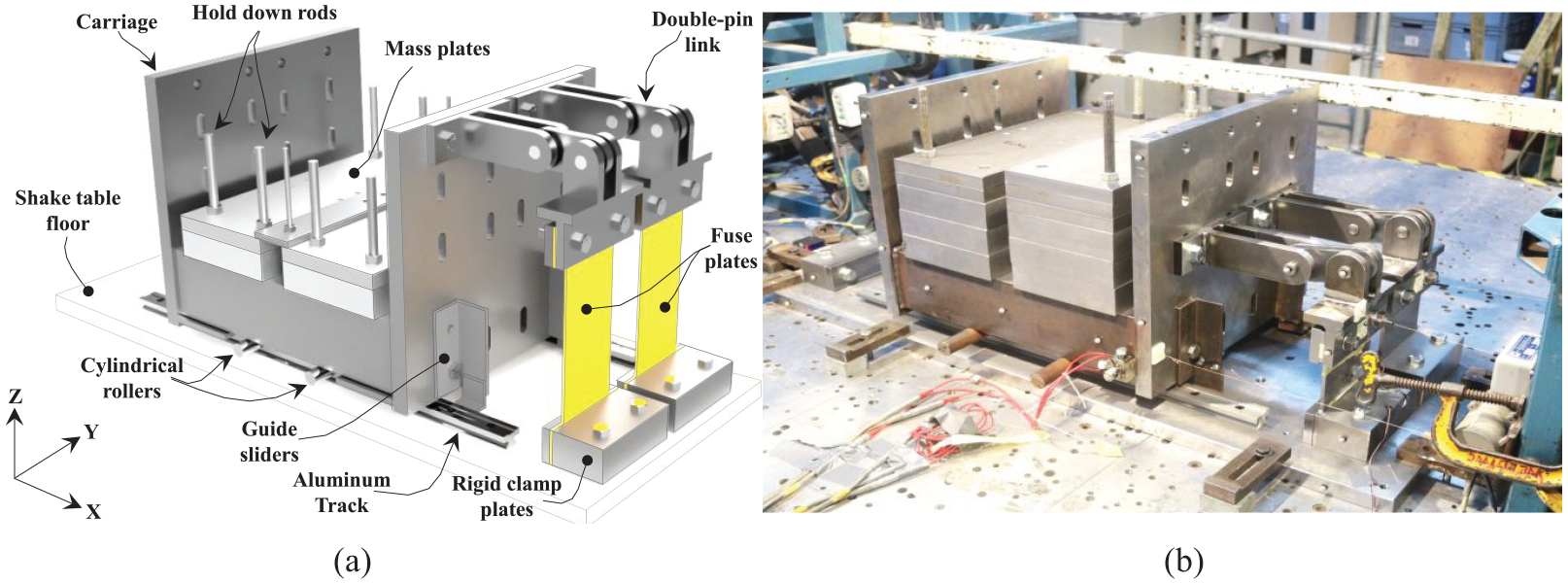
Overview of the test setup and its components: (a) 3D CAD model and (b) actual lab assembly.
The fuse represents the deformable yielding element between the nonstructural element (i.e. moving mass) and the supporting structure (i.e. building floor). In practice, the fuse could have a range of geometries incorporating one or more angles, channels, anchors, and so on. In this study, since the objective is to demonstrate the fuse concept regardless of configuration, the structural fuses are simple steel plates with uniform or reduced width as shown in Figure 3a. The fuse’s bottom region is sandwiched between two rigid plates and clamped rigidly to the shake table floor using two pre-tensioned high-strength M16 bolts and threaded table holes. This provides the fuse with a nearly fixed-end boundary condition in its lower region. The upper region is clamped by two plates and connected to the carriage wall through a rigid double-pin assembly with 20 mm pins and shrink-fitted ball joints, allowing in-plane rotation. This arrangement provides the fuse with a nearly free-end boundary condition. Essentially, the fuse plates represent the strength and stiffness component of an SDoF system in the attachment between the structure and the nonstructural component.
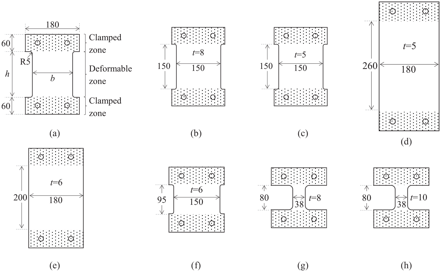
Fuse plate configuration: (a) typical layout, (b)–(h) the seven different fuse types (dimensions in mm): (a) typical detail, (b) Fuse 1, (c) Fuse 2, (d) Fuse 3, (e) Fuse 4, (f) Fuse 5, (g) Fuse 6, and (h) Fuse 7.
It is worth noting that the single-sided placement of the fuses was chosen, rather than a double-sided placement, as it eliminates the need to maintain symmetry in the setup which can be challenging when dealing with tight tolerances. In addition, achieving the target fuse stiffness (considering the size and weight constraints of the test) was more attainable with two fuses rather than four for the double-sided case.
Test matrix
A total of 14 specimens were tested, as summarized in Table 1. Each specimen is characterized by its fundamental period and damping coefficient, as deduced from free vibration tests (see the “Test Procedure” section). Each specimen comprises two fuse plates connected to the carriage. The employed fuse plates have seven different geometries, as shown in Figure 3b to h. Each fuse is characterized by three geometrical parameters: the height (h), the width (b), and the thickness (t) of the fuse plate’s mid-height deformable and yielding region. It is worth noting that although this testing campaign did not target any specific piece of nonstructural equipment, the properties of the considered specimens have a physical meaning. The tested specimens represent a wide range of full-scale acceleration-sensitive equipment with masses from 199 to 806 kg and periods between 0.15 and 0.45 s. Actual equipment in industrial facilities could have masses and periods within the considered range (e.g. a pump at a refinery plan, see Kazantzi et al., 2022) as well as mechanical/electrical equipment and medical instruments in hospitals (e.g. medical gas tanks, MRI scans) and other critical facilities.
Summary of the specimens’ geometric and dynamic properties
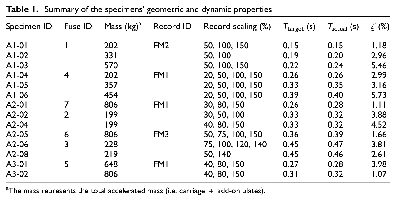
The mass represents the total accelerated mass (i.e. carriage + add-on plates).
Three floor-acceleration records are used as input motions for the shake table tests. They correspond to floor motions (FM) recorded in instrumented buildings in California, USA (CESMD 2018) during the 1989 Loma Prieta and the 1994 Northridge earthquakes (Kazantzi et al., 2020b), which were carefully selected to represent realistic severe motions that nonstructural components can be subjected to. The main characteristics of these records—labeled herein FM1, FM2, and FM3—are summarized in Table 2. For the Loma Prieta records, the floor acceleration spectra are characterized by large amplifications at or close to the fundamental period of the instrumented building (see Figures 4a and 3b, that is, T1 = 0.33 s and T1 = 0.19 s for FM1 and FM2, respectively) whereas the third case has its maximum floor acceleration spectral ordinate at the second modal period of the supporting structure (see Figure 4c, that is, T2 = 0.45 s).
Summary of floor records used in the shake table tests
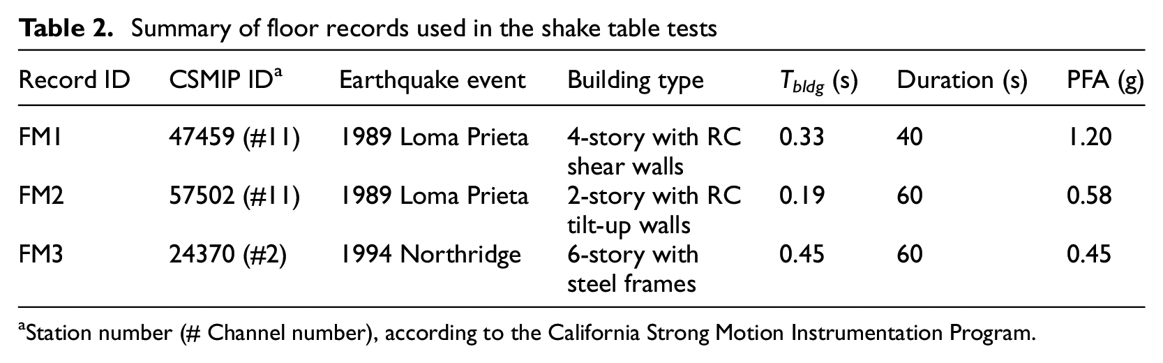
Station number (# Channel number), according to the California Strong Motion Instrumentation Program.
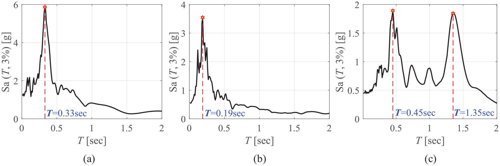
The elastic acceleration-response spectra of the three input floor motions: (a) FM1, (b) FM2, and (c) FM3.
Each of the 14 specimens was subjected to one of the three floor motions. For a given specimen, a series of sequential tests were conducted where the employed floor motion was increasingly scaled by up to 150% of the recorded intensity. The record scaling factors (SF) employed for each specimen are summarized in Table 1. In total, 45 tests were conducted.
Material properties
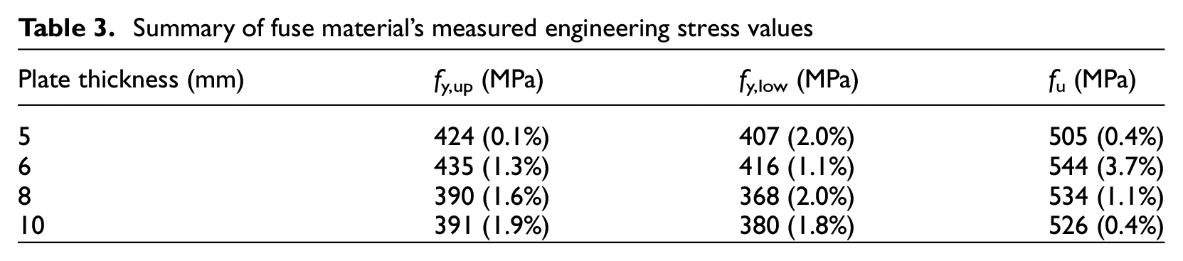
All steel fuses were fabricated from S355 grade steel (i.e. nominal yield stress,
Summary of fuse material’s measured engineering stress values
Instrumentation
An array of displacement and acceleration transducers was used to capture the motion of the carriage, the fuse, and the shake table at various locations. Figure 5 shows the instrumentation layout. Two accelerometers were employed to measure the shake table and carriage absolute accelerations in the three orthogonal directions X, Y, and Z. Eight string potentiometers were likewise used to measure the in-plane (i.e. X-direction) displacements of the carriage and at the top end of each fuse plate relative to the table. The string potentiometers were located at the eight corners of the carriage to confirm the rigid movement of the carriage in-plane and the absence of twisting during shaking. For measurement redundancy and to track possible uplift or twisting of the carriage, a wireless system with 12 light-emitting diodes (LED) targets was also employed to track absolute displacements of the shake table, carriage, and fuse plate in the three-dimensional space. It should be noted that carriage twisting and uplift were negligible in all tests. Out-of-plane accelerations were practically zero, and vertical accelerations were found in all tests to be below 0.1 g. Finally, a single strain gauge was installed at the middle of each fuse, 30 mm from the bottom clamped zone, to help monitor the local evolution of plastic deformations.
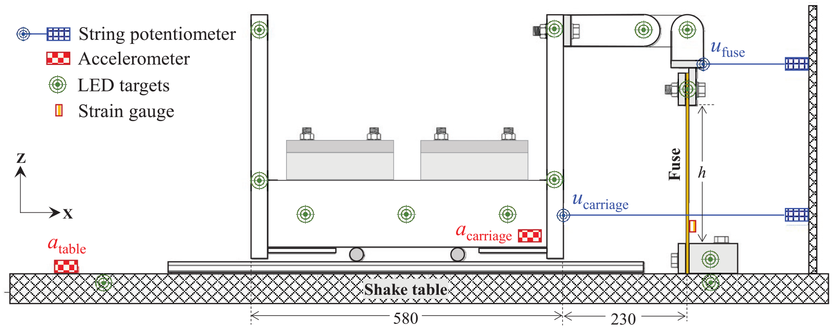
Instrumentation layout.
Test procedure
A free vibration test was first conducted for each specimen to identify the system’s dynamic properties (i.e. the fundamental period of vibration Tactual and the equivalent viscous damping coefficient ζ). This step is important to confirm that Tactual is as close as possible to Ttarget which corresponds to the peak of the elastic floor spectra for a given floor motion (refer to Table 2). Fine-tuning of the mass was carried out when necessary to improve the match to Ttarget.
The free vibration test was realized by manually shaking the carriage (i.e. forced vibration) and then analyzing the free vibration with a decaying amplitude of motion. Figure 6 shows a sample of the decaying motion of the carriage displacement as recorded by the wireless tracking system. The period of the system is then inferred from the difference in time between two consecutive decaying cycles’ peaks, or as the difference in time to complete a certain number of cycles of vibration divided by the number of cycles. The energy dissipation in the carriage is a combination of rolling friction in the cylindrical rollers, deformations in the nearly rigid U-shaped carriage, friction in the upper pins, and radiation damping. This was represented by an equivalent viscous damping coefficient. For each carriage configuration, the equivalent viscous damping coefficient, ζ, was inferred from the dynamics-based principles as k/(4π2 + k2)0.5, where k is the slope of the linear function that fits the logarithm of the decayed carriage amplitude of motion as a function of the cycle number (Chopra, 2017).
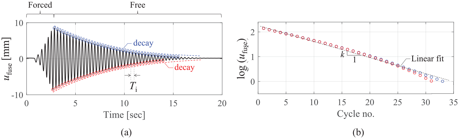
Illustration of period and damping coefficient deduction from free vibration test.
Referring to Table 1, the measured periods of the specimens match well the target periods, with the difference not exceeding ±10%. The inferred damping ratios varied from 1% to 6%. A weak positive correlation is observed between the damping coefficient and the system’s period. However, this correlation is associated with large variability that should be considered in numerical studies.
All recorded raw signals (accelerations and displacements) are processed first using a baseline correction (signal offsetting based on the average of first 100 data points) followed by a second-order low-pass Butterworth filter with a cutoff frequency at 10 Hz, which was applied to all recorded time histories to remove high-frequency noise present in the signals. The filtering process efficiently removed noise without compromising the signals’ amplitude or main frequency content characteristics. One filtering example is demonstrated in Figure 7.
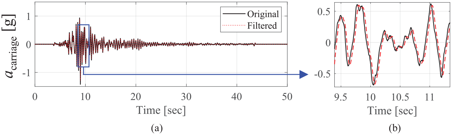
Illustration of the low pass filtering of the recorded signals.
Typical test results
Figure 8a depicts four major input or response quantities from each test: (1) the carriage’s filtered absolute acceleration history as recorded by the accelerometer (acarriage), (2) the shake table’s recorded and filtered absolute acceleration history as recorded by the accelerometer (atable), (3) the carriage’s recorded and filtered absolute displacement history as recorded by the wireless tracking system at the fuse’s top pin (ucarriage), and (4) the shake table’s recorded and filtered absolute displacement history as recorded by the wireless tracking system at the fuse’s base (utable). Two quantities are derived from the processed histories: the inertia force and the fuse’s relative displacement. The inertial force exerted by the carriage on the two attached fuse plates is then computed as the product of the system’s mass (see Table 1) and acarriage. Meanwhile, the relative deformation of the fuse (urel) is computed as the difference between absolute horizontal displacements ucarriage and utable. Figure 8b to d shows the F–urel responses of the A3-01 specimen when subjected to FM1, scaled by 40%, 80%, and 150%.
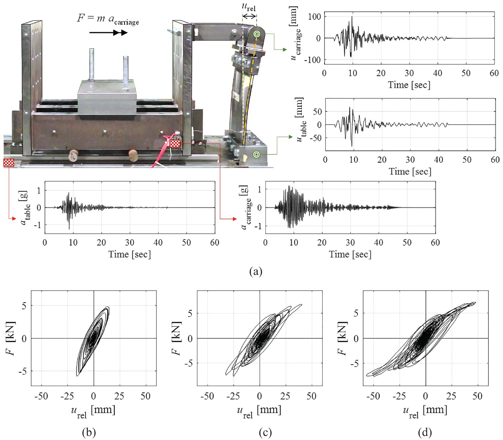
Specimen A3-01: (a) recorded displacement and acceleration histories, and deduced force-deformation responses at (b) SF = 40%, (c) SF = 80%, and (d) SF = 150%.
Online data repository
The curated test data are organized and made publicly available through online repositories within both the NHESRI DesignSafe (Elkady et al., 2025b) and GitHub (Elkady et al., 2025a) platforms. Figure 9 shows the organizational tree of the online repository. The repository contains two main folders: one for the input floor motions containing the unscaled acceleration histories and one for the specimens’ recorded and deduced data. Each specimen has a dedicated folder containing the free vibration test data (one test per specimen), which is the displacement history of the carriage (ucarriage, free) as recorded by the wireless tracking system. A sub-folder is included for each specimen test (i.e. under varying scaled floor motions), containing the recorded and filtered histories of the four main response quantities described earlier, the deduced force versus relative displacement of the fuse, and the strain history of the fuse. All data are provided in text file format (.txt). An additional MATLAB® data file (.mat) (MATLAB 2019) is provided for each test, which includes the summary information of the test, including the geometric, material, and dynamic properties of the specimen. Furthermore, in the GitHub repository, a MATLAB script is provided to assist users in extracting the data from the files and in generating the different response plots.
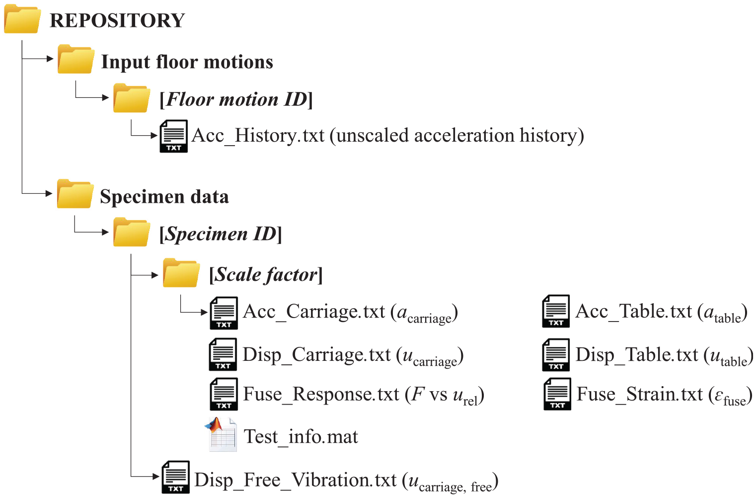
The organizational tree of the online data repository.
Summary and conclusion
An experimental campaign was conducted on a shake table to examine and demonstrate the efficacy of utilizing sacrificial steel yielding elements (fuses) to attach nonstructural components and limit the acceleration demand and the consequent damage they experience during earthquakes. In total, 45 shake table tests were carried out on different single-degree-of-freedom systems with varying dynamic characteristics subjected to real floor motions recorded from instrumented buildings in past earthquakes. The details of the test specimens and the recorded and deduced response quantities are described in detail. The curated data are also organized and publicly available through an online repository. The data can be instrumental in validating analytical and computational models such that the acceleration-control concept can be further investigated and developed. The results open new directions for research in the significant improvement of seismic performance of nonstructural components and they can easily find their way into prospective design codes.
Footnotes
Acknowledgements
Special thanks are given to the laboratory personnel at the University of Bristol for their assistance during the shaking table testing. Any opinions, findings, conclusions, or recommendations expressed in this paper are those of the authors and do not necessarily reflect the views of sponsors.
Declaration of conflicting interests
The author(s) declared no potential conflicts of interest with respect to the research, authorship, and/or publication of this article.
Funding
The author(s) disclosed receipt of the following financial support for the research, authorship, and/or publication of this article: Funding was provided by the Seismology and Earthquake Engineering Research Infrastructure Alliance for Europe, funded by the EU/H2020 under grant agreement 730900 (SERA), Project #12 NSFUSE. This funding is greatly appreciated.
Data and resources
The data generated by the experimental campaign discussed in this paper is made publicly available through online repositories within the NHERI DesignSafe (Elkady et al., 2025b) and GitHub platforms (Elkady et al., 2025a).