
Abstract
Many monotonic and cyclic tests have been conducted on cold-formed steel framed shear walls in the last 20 years. Cold-formed steel framed shear wall provisions in AISI S240, AISI S400, and ASCE 41 are supported by the data obtained through these tests. The main objective of this article is to introduce a recently compiled cold-formed steel framed shear wall test database, to reveal the database structure, and to explain how to access and present the data. Most recently, the database has been standardized and expanded to include additional tests, complete cyclic information from tests, limit states, and code prediction information. The database structure incorporates a central Excel spreadsheet that includes descriptive information; ordered plain text files for each individual test; and custom MATLAB codes, which can read, process, and plot designated database subsets. The provided database can advance the understanding and modeling of cold-formed steel framed shear walls.
Introduction
Various systems contribute to the lateral resistance of buildings framed with cold-formed steel (CFS). The overall behavior, design, and performance of CFS lateral force-resisting systems are summarized in the study by Madsen et al. (2016). Predicting the lateral response of CFS-framed shear walls can be complex, as considerable nonlinearity may be generated at connections, in any sheathing materials, or in the framing steel itself. As a result, experimental testing has taken a central role in studying the behavior of CFS-framed lateral force-resisting systems, as well as providing strength and drift guidance for these systems.
Design provisions for lateral force-resisting systems in the North American Standard for CFS Structural Framing (AISI S240-15) (American Iron and Steel Institute, 2015a), the North American Standard for Seismic Design of CFS Structural Systems (AISI S400-15) (American Iron and Steel Institute, 2015b), and the Seismic Evaluation and Retrofit of Existing Buildings standard (ASCE/SEI 41-17) (American Society of Civil Engineers, 2017) are constructed based on available CFS-framed shear wall test data. The shear wall strength tables in AISI S400 can only provide the design shear capacity. However, the seismic evaluation, retrofit, and design of CFS structures per ASCE 41 and further performance-based earthquake engineering require information beyond only shear capacity. Therefore, the integration of tested CFS-framed shear walls into a comprehensive database is expected to provide a necessary means for improving the understanding and design of CFS-framed systems.
Currently, 700 individual tests drawn from 29 different primary sources (Al-Kharat and Rogers, 2005, 2006; Balh and Rogers, 2010; Blais, 2006; Boudreault, 2005; Branston, 2004; Briere and Rogers, 2018; Chen, 2004; Comeau, 2008; DaBreo, 2012; DaBreo et al., 2014; Elhaji, 2005; Hikita, 2006; Kochkin and Hill, 2006; Liu et al., 2012; Lu, 2015; Morello, 2009; Morgan et al., 2002; Nguyen et al., 1996; Ong-Tone, 2009; Ong-Tone and Rogers, 2009; Rizk and Rogers, 2018; Rokas, 2006; Salenikovich and Dolan, 1999; Santos and Rogers, 2018; Serrette et al., 1997; University of California, Irvine (UCI), 2004; Velchev, 2008; Yu and Chen, 2009; Yu et al., 2007a, 2007b) are incorporated into the CFS-framed shear wall test database, published at DesignSafe-CI (Zhang et al., 2022), which is introduced herein. These collected tests include all CFS-framed shear wall tests that underpin AISI S240-15 and AISI S400-15. An initial version of this database (Ayhan et al., 2018; Ayhan et al., 2016) supported the recent revision to ASCE 41-17 for CFS framing. In the initial version database research, the expected strength of CFS-framed shear walls is explored, a commentary on code provisions is provided, and areas of potential improvement and need are discussed. Seismic overstrength and seismic fragility function research efforts for CFS-framed shear walls were also conducted based on the database (Haghpanah and Schafer 2021; Schafer et al., 2020). It is worth noting that recent testing, at McGill University, exploring CFS-framed steel sheet sheathed shear walls with higher capacity providing up to 145,939 N/m (10,000 lb/ft) in capacity (Briere and Rogers, 2018; Rizk and Rogers, 2018; Santos and Rogers, 2018) has been incorporated into the database.
Database structure and detail
The database has a specific folder structure, a central Excel spreadsheet database, and an analysis engine driven by custom MATLAB (2022) codes. There are three subfolders within the database home folder: “Data,”“Reference,” and “Analysis.” The “Data” subfolder contains seven folders named after university/research-center/research-project at which the shear wall tests were conducted. Within every affiliation folder, there is a “main” folder containing a series of ordered plain text files, each corresponding to a shear wall test data. A “Reference” subfolder under the home folder stores source literature (mainly test reports and thesis) corresponding to each test data group. The last subfolder in the database home folder (“Analysis”) accommodates all the custom MATLAB codes, which read, process, and plot the database data.
The central database Excel spreadsheet organizes all salient features of shear wall test specimens, as well as results, which can be read into and utilized by custom MATLAB codes. Some of the key field information in the Excel spreadsheet is listed in Table 1, while the detailed database field dictionary for the central database Excel spreadsheet is summarized in the Appendix. English customary units have been adopted within the database. The paths of the raw test data text files are also stored inside the central Excel spreadsheet, which can be accessed by the custom MATLAB codes to read the raw plain text test data files. The link information between a certain source and its corresponding reference is saved in a separate sheet within the central Excel spreadsheet. It is worth noting that the Excel spreadsheet is intended to be input to the analysis engine. Parameters selected from the test data response (e.g. the peak strength) are handled in the analysis engine but not stored in the spreadsheet. This is an intentional decision to require the analyst to utilize the data files, not just the input spreadsheet.
Data fields in the central database Excel spreadsheet
The analysis engine is composed of a few customized MATLAB scripts reading in both the central spreadsheet and raw plain text test data files following the accurate file path provided by the spreadsheet for deeper manipulation of the data. These customized scripts can process test data, visualize test results of a specific test or a designated database subset, and further explore the database (e.g. by comparing normalized results of different tests).
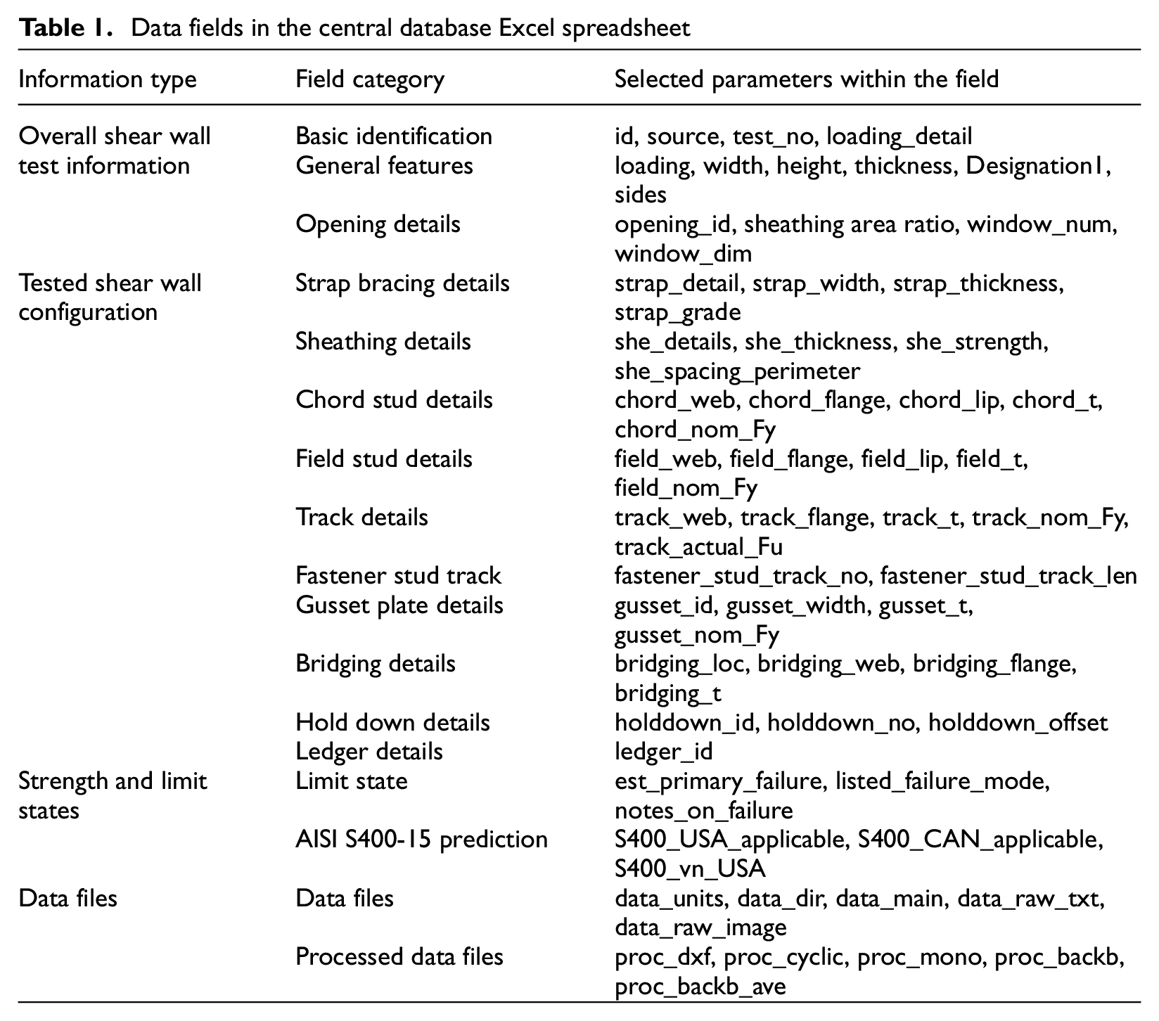
The four largest groups of tested shear walls can be classified by sheathing type. The normalized force-deformation responses of all the shear wall tests with wood structural panels (WSP), steel sheet sheathing (SS), steel strap bracing (STRAP), and gypsum board sheathing (GYP) are presented in Figure 1. In Figure 1, the normalized shear force V implies the peak base shear force per unit wall length, and the drift ratio means the ratio between shear wall lateral drift and wall height. The figure presents the overall lateral force-drift hysteretic shape of CFS-framed shear wall tests separated by sheathing types. Among these 700 shear wall tests, WSP-sheathed shear wall tests demonstrate a maximum absolute shear capacity per unit length of 84,537 N/m (5,793 lb/ft); STRAP-braced shear wall tests feature a maximum absolute shear capacity per unit length of 56,054 N/m (3,841 lb/ft); GYP-sheathed shear wall tests present a maximum absolute shear capacity per unit length of 19,163 N/m (1,313 lb/ft); SS-sheathed shear wall tests exhibit a maximum absolute shear capacity per unit length of 164,535 N/m (11,274 lb/ft).
Normalized lateral force-drift responses for all shear wall tests in the database.
Database usage sample: codes and outputs
There are three sample MATLAB (2022) codes available in the CFS-framed shear wall data set (in the “Analysis” folder). The first sample code is used when the database user is interested in the results of a specific test in the database. In such a case, the user can get the test ID from the central spreadsheet and then use the MATLAB code and the known test ID to plot the test force per unit wall length vs drift ratio curve and get the peak force and corresponding drift output in the MATLAB Command Window.
The second sample code addresses the situation in which the user needs to analyze all the tests whose configuration matches a specific cell in the strength Table E 1.3-1 for CFS-framed shear walls sheathed with WSP in AISI S400-15. This sample code can plot the force per unit wall length vs drift ratio curves of all matched tests and get the average peak shear force and corresponding average drift at peak shear force outputs in the MATLAB Command Window. The sample code can be modified to deal with all the tests whose configuration matches a specific cell in the strength Table E 2.3-1 for CFS-framed shear walls sheathed with SS in AISI S400-15. It is important to note that many of the tests in the shear wall database are not compliant with detailing requirements in the design specifications—it is up to the analyst to ensure that the selected data are appropriate for their analysis—the analysis code and spreadsheet provide necessary information to make this determination, and a field exists in the spreadsheet as to whether or not the test is judged to be compliant with AISI S400-15.
The third sample code enables the user to plot the force per unit wall length vs drift ratio curves for all tests with a particular type of sheathing (WSP, GYP, SS, STRAP), or with a specific load protocol (monotonic or cyclic). The code also generates various histogram plots of peak force per unit wall length separated or not separated by sheathing types.
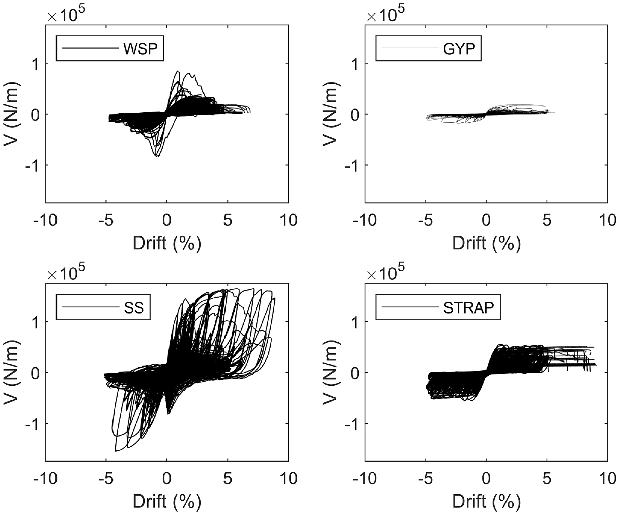
In the first sample code (“Database_Usage_Example1.m”), there are three input parameters including “ID_Input,”“write_switch,” and “units_output.” The “ID_Input” should be a unique test ID (tests IDs are listed in the first column of the database center spreadsheet), while the parameter “write_switch” determines whether the code will export the force-deformation curves to external files. For example, if the “ID_Input” is specified as 682 and the “write_switch” is “1” (“1” means TRUE and exporting the plot to external files, otherwise means FALSE), running the code will output the peak shear force and drift corresponding to the peak strength in the MATLAB Command Window in addition to plotting and exporting figures similar to that shown in Figure 2. In Figure 2, V denotes the shear wall base shear force per unit wall length, and the drift ratio implies the ratio between the shear wall lateral drift and the wall height. The last parameter of “units_output” controls the unit system for the output data and figure. Either “N-m” or “lbf-inch” can be used for the “units_output” input, resulting in two different unit systems.
The output of sample analysis code 1: shear force per unit wall length vs drift ratio curve (test ID: 682).
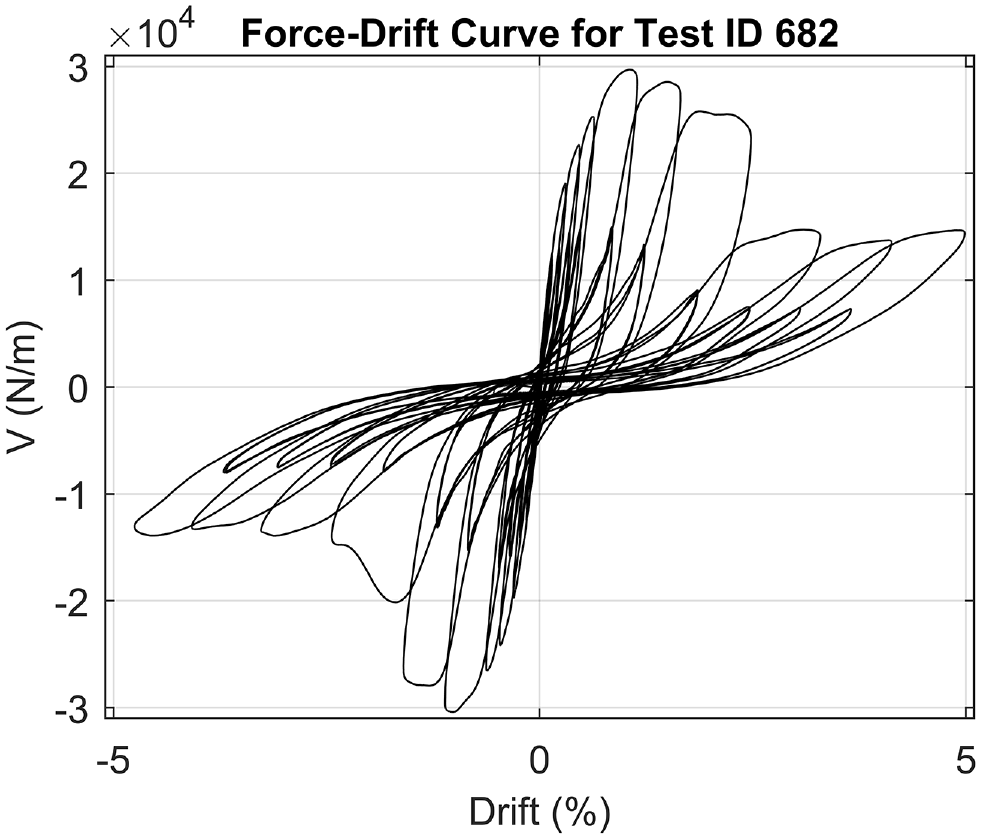
The second sample code file is “Database_Usage_Example2.m.” The code reads all the test data of shear wall test configurations with oriented strand board (OSB) sheathing and outputs a series of mean peak forces and corresponding mean drifts (both positive and negative loading directions) of tests matching each cell with OSB sheathing configuration in Table E1.3-1 of AISI S400-15 in the MATLAB Command Window. In addition, the sample code generates a shear force per unit width-drift ratio curve plot (as shown in Figure 3) covering all the shear wall configurations with OSB sheathing in Table E1.3-1 of AISI S400-15. In Figure 3, red horizontal lines represent code-predicted values, and data are not available if horizontal lines or test data curves are not presented. The vertical array in Figure 3 represents various designation thicknesses of stud and track (“t” implies framing thickness) while the horizontal array in Figure 3 shows the fastener spacing at sheathing panel edges (“s” implies spacing). The parameter “write_switch” is set as “1,” and the parameter “units_output” is set as “N-m,” playing similar roles as the first sample code.
An output of sample analysis code 2: shear force per unit wall length vs drift ratio curves of all the cyclic tests matching CFS-framed OSB-sheathed shear wall configurations in Table E1.3-1 of AISI S400-15.
As mentioned earlier, the third sample code (“Database_Usage_Example3.m”) helps the user to analyze all tests with a particular type of sheathing (GYP adopted herein as an example) or load protocol (cyclic loading chosen in the sample code) and further plot the test shear force-drift curves with a certain detailing feature in the same figure. Within the database, 348 tests employ a cyclic loading protocol, while 352 tests adopt a monotonic one. Regarding sheathing type, 279 tests utilize WSPs; 241 tests employ SS sheathing; 117 tests use strap bracing; 40 tests adopt GYP sheathing; and finally, the remaining 23 tests use other configurations. The third sample code also generates two histogram plots based on absolute peak shear force per unit wall length to help understand the shear wall strength value distribution: One histogram presents the data of all tests not separated by sheathing type, while the other is divided by sheathing type employed.
In the third sample code, four input parameters need to be defined: “Sheathing_Input” to specify the sheathing type of interest, “Loading_Input” to determine the loading protocol, “write_switch” to define whether the code will export the plots to external files, and “units_output” to choose the unit system used in the plots. For example, if “GYP,”“cyclic,”“1,” and “N-m” are defined for the aforementioned four inputs, respectively, the code can generate plots as that in Figures 4–7: Figure 4 shows the force per unit wall length vs drift ratio curves for all tests with GYP (overlayed); Figure 5 presents the force per unit wall length vs drift ratio curves for all tests where cyclic loading is used; Figure 6 plots a histogram for the absolute peak force per unit wall length of all the tests within this database; and Figure 7 shows a stacked histogram for the absolute peak force per unit wall length of all the tests where histogram columns is divided according to the number of tests of each sheathing type. This stacked histogram output could help in better understanding of the shear wall strength distribution for tests with different sheathing materials.
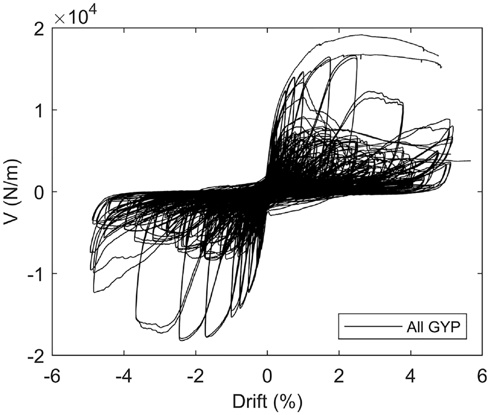
An output of sample analysis code 3: shear force per unit wall length-drift ratio curves of all the cold-formed steel framed shear wall tests with gypsum board sheathing.
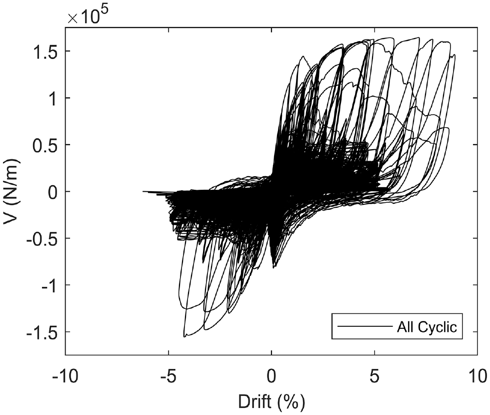
An output of sample analysis code 3: peak shear force per unit wall length-drift ratio curves of all the cold-formed steel framed shear wall tests under cyclic loading.
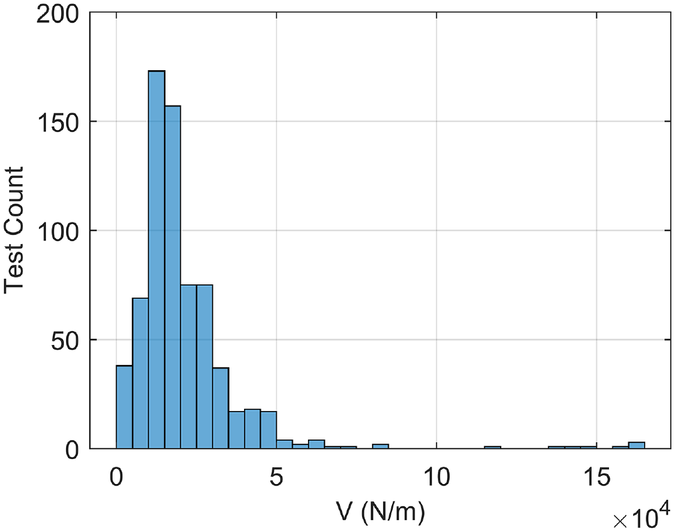
An output of sample analysis code 3: histogram of absolute peak shear force per unit wall length for all the tests.
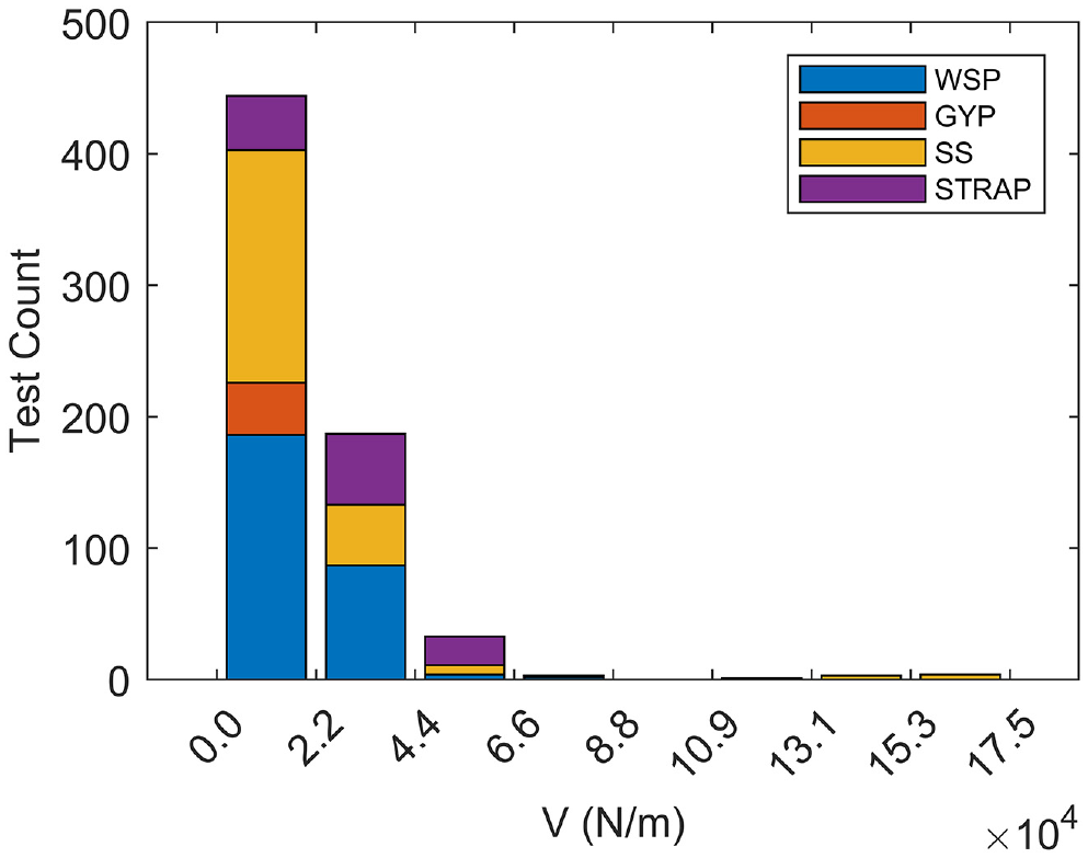
An output of sample analysis code 3: stacked histogram of absolute peak shear force per unit wall length for all the tests (grouped by sheathing type).
Database application discussion
The CFS-framed shear wall database has numerous potential uses. For design specifications, the data can be used to refine strength and drift requirements. In addition, the data provide a direct means to assess the overstrength and ductility of shear walls. As one contemplates a more analysis-based path for predicting lateral performance, the data provide a direct means to incorporate tested shear walls in numerical models. Also, the tests can provide benchmarks for high-fidelity models or semi-analytical/phenomenological model approaches. It is also possible to use the database to assess specific aspects of the nonlinear response—for example, cyclic degradation, post-peak slope, ultimate drift, and so on. Furthermore, the database is large enough to assess statistics of response and directly explore component and subsystem reliability. In addition, the quite large volume of the database also could make it useful as a training set for modern machine learning methods to predict strength or full shear-deformation response. It is worth noting that the authors are aware of recent additional tests that could also be used to further expand the database, particularly on new sheathing materials. The work herein is based on AISI S400-15, and further adjustments based on the updated version AISI S400-20 can be processed.
Summary and conclusions
A database composed of 700 tested CFS-framed shear walls has been assembled. Complete descriptive information and lateral force-deformation response are included in the database. The tests included in the database cover a wide range of sheathing types: wood structure panel, steel sheet, strap bracing, gypsum board, and a small number of additional miscellaneous configurations. The database incorporates all necessary information and data, including test configuration information, complete test response, limit states, and American Iron and Steel Institute code prediction information. The basic database structure is introduced, and three example MATLAB codes for presenting how the database can be utilized are provided. The database offers important and useful information to advance the understanding and modeling of lateral force-resisting systems in CFS framing.
Footnotes
Appendix
Detailed data field dictionary for the CFS-framed shear wall database
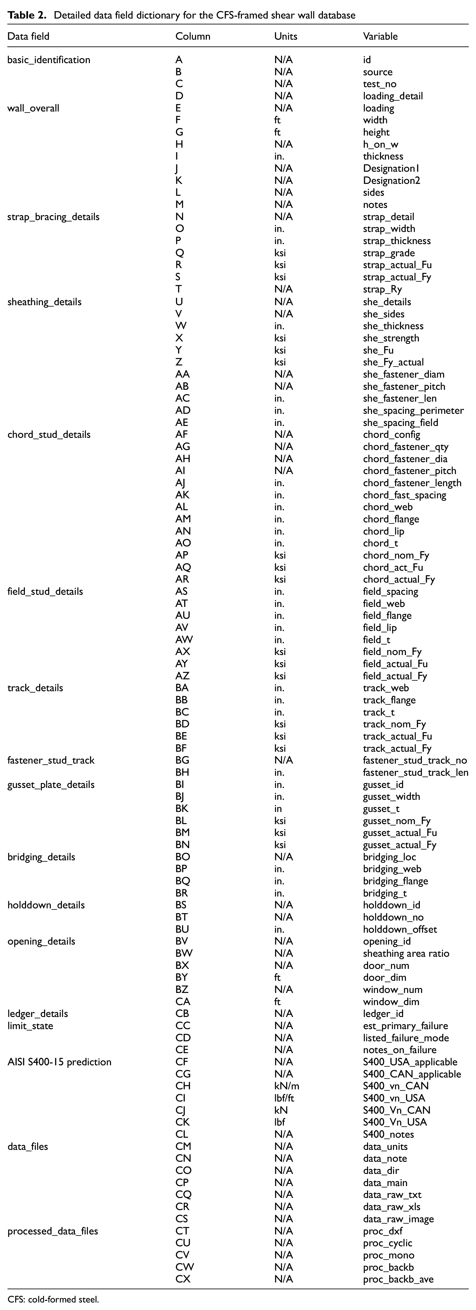
| Data field | Column | Units | Variable |
|---|---|---|---|
| basic_identification | A | N/A | id |
| B | N/A | source | |
| C | N/A | test_no | |
| D | N/A | loading_detail | |
| wall_overall | E | N/A | loading |
| F | ft | width | |
| G | ft | height | |
| H | N/A | h_on_w | |
| I | in. | thickness | |
| J | N/A | Designation1 | |
| K | N/A | Designation2 | |
| L | N/A | sides | |
| M | N/A | notes | |
| strap_bracing_details | N | N/A | strap_detail |
| O | in. | strap_width | |
| P | in. | strap_thickness | |
| Q | ksi | strap_grade | |
| R | ksi | strap_actual_Fu | |
| S | ksi | strap_actual_Fy | |
| T | N/A | strap_Ry | |
| sheathing_details | U | N/A | she_details |
| V | N/A | she_sides | |
| W | in. | she_thickness | |
| X | ksi | she_strength | |
| Y | ksi | she_Fu | |
| Z | ksi | she_Fy_actual | |
| AA | N/A | she_fastener_diam | |
| AB | N/A | she_fastener_pitch | |
| AC | in. | she_fastener_len | |
| AD | in. | she_spacing_perimeter | |
| AE | in. | she_spacing_field | |
| chord_stud_details | AF | N/A | chord_config |
| AG | N/A | chord_fastener_qty | |
| AH | N/A | chord_fastener_dia | |
| AI | N/A | chord_fastener_pitch | |
| AJ | in. | chord_fastener_length | |
| AK | in. | chord_fast_spacing | |
| AL | in. | chord_web | |
| AM | in. | chord_flange | |
| AN | in. | chord_lip | |
| AO | in. | chord_t | |
| AP | ksi | chord_nom_Fy | |
| AQ | ksi | chord_act_Fu | |
| AR | ksi | chord_actual_Fy | |
| field_stud_details | AS | in. | field_spacing |
| AT | in. | field_web | |
| AU | in. | field_flange | |
| AV | in. | field_lip | |
| AW | in. | field_t | |
| AX | ksi | field_nom_Fy | |
| AY | ksi | field_actual_Fu | |
| AZ | ksi | field_actual_Fy | |
| track_details | BA | in. | track_web |
| BB | in. | track_flange | |
| BC | in. | track_t | |
| BD | ksi | track_nom_Fy | |
| BE | ksi | track_actual_Fu | |
| BF | ksi | track_actual_Fy | |
| fastener_stud_track | BG | N/A | fastener_stud_track_no |
| BH | in. | fastener_stud_track_len | |
| gusset_plate_details | BI | in. | gusset_id |
| BJ | in. | gusset_width | |
| BK | in | gusset_t | |
| BL | ksi | gusset_nom_Fy | |
| BM | ksi | gusset_actual_Fu | |
| BN | ksi | gusset_actual_Fy | |
| bridging_details | BO | N/A | bridging_loc |
| BP | in. | bridging_web | |
| BQ | in. | bridging_flange | |
| BR | in. | bridging_t | |
| holddown_details | BS | N/A | holddown_id |
| BT | N/A | holddown_no | |
| BU | in. | holddown_offset | |
| opening_details | BV | N/A | opening_id |
| BW | N/A | sheathing area ratio | |
| BX | N/A | door_num | |
| BY | ft | door_dim | |
| BZ | N/A | window_num | |
| CA | ft | window_dim | |
| ledger_details | CB | N/A | ledger_id |
| limit_state | CC | N/A | est_primary_failure |
| CD | N/A | listed_failure_mode | |
| CE | N/A | notes_on_failure | |
| AISI S400-15 prediction | CF | N/A | S400_USA_applicable |
| CG | N/A | S400_CAN_applicable | |
| CH | kN/m | S400_vn_CAN | |
| CI | lbf/ft | S400_vn_USA | |
| CJ | kN | S400_Vn_CAN | |
| CK | lbf | S400_Vn_USA | |
| CL | N/A | S400_notes | |
| data_files | CM | N/A | data_units |
| CN | N/A | data_note | |
| CO | N/A | data_dir | |
| CP | N/A | data_main | |
| CQ | N/A | data_raw_txt | |
| CR | N/A | data_raw_xls | |
| CS | N/A | data_raw_image | |
| processed_data_files | CT | N/A | proc_dxf |
| CU | N/A | proc_cyclic | |
| CV | N/A | proc_mono | |
| CW | N/A | proc_backb | |
| CX | N/A | proc_backb_ave |
CFS: cold-formed steel.
Acknowledgements
The database itself has been published at DesignSafe-CI (Zhang et al., 2022). Building this database has included generosity and help from a large number of people. Postdoctoral researcher Dr. Deniz Ayhan Moen initiated the first version of the database and participated in the ASCE 41 analysis using the first version. Master’s student Sam Baer contributed to the expansion of the main database, and doctoral student Dr. Fardad Haghpanah provided significant error-checking when he was utilizing the database. The authors would like to express gratitude for the generosity of the original researchers of all these shear wall tests. Professor Cheng Yu provided source data not publicly available to improve the database information. Professors Tara Hutchinson and Kara Peterman in the CFS-NHERI effort provided feedback on the database and its application along with their doctoral students Amanpreet Singh, Hernan Casteneda, and Fani Derveni. In addition, several members of the Lateral Committee at the American Iron and Steel Institute have provided feedback on the database and its application. Any opinions, findings, and conclusions or recommendations expressed in this material are those of the author(s) and do not necessarily reflect the views of the U.S. National Science Foundation or others acknowledged.
Declaration of conflicting interests
The author(s) declared no potential conflicts of interest with respect to the research, authorship, and/or publication of this article.
Funding
The author(s) disclosed receipt of the following financial support for the research, authorship, and/or publication of this article: This work is a part of the research project, Seismic Resiliency of Repetitively Framed Mid-Rise Cold-Formed Steel Building (CFS-NHERI), which is supported by the U.S. National Science Foundation under grant no. 1663348 and no. 1663569.