
Abstract
This article describes a new multivalve configuration for achieving both high speed and high resolution in pneumatically driven soft robotic actuators. The proposed method utilizes dual on/off valves with differing orifice sizes in both the charge and discharge paths of the pneumatic circuit. The multiple-valve arrangement provides five states of flow-rate control, which can provide high flow rate for large step changes in pressure, and fine pressure control for precision positioning or force control. Compared with a proportional valve, the proposed method is physically smaller, lower cost, and significantly faster in charging and discharging a soft actuator. The performance of the proposed multivalve system is evaluated using a dual hysteresis control strategy, where the valve combination is dependent on pressure error. The proposed method is experimentally compared with two single-valve configurations, and the results demonstrate a significant improvement in both speed and accuracy. The proposed method is suited to applications that require a fast response between arbitrary set-points and precise control of position or interaction force.
Keywords
Introduction
Fluidic soft robots are traditionally driven by a system of pumps and valves.1–3 Their applications include minimally invasive surgery, 4 rehabilitation,5,6 and elderly assistance. 7 Compared with rigid robots, soft robots provide a desirable combination of high compliance, low mass, and user safety. Soft robots are typically driven by a pneumatic source with on/off valves for pressurization and discharge. Due to the manufacturer-specified minimum mechanical opening time of valves, a trade-off exists between the pressure rise time and the minimum achievable pressure change. The orifice diameter determines the maximum flow rate, while the orifice diameter and minimum on-time determine the minimum pressure variation. As shown in Figure 1, a large orifice provides a fast response for large pressure changes but is unable to make small pressure variations. Small orifices provide more precise pressure control but have a slow step response for large changes in pressure.8,9 This limitation causes the actuator’s performance to be constrained by the pneumatic supply rather than the actuator mechanics. As a result, the actuator cannot fully utilize its potential range of motion, force output, or actuation speed, leading to an under-utilized actuator and suboptimal performance.4,10–12

Trade-off between the speed and resolution of a solenoid valve. The orifice diameter (mm) of the tested valve decreases to the right of the graph. Resolution on the y-axis refers to the smallest pressure variation that a pneumatic system can track using the corresponding valve diameter.
The main components of compressed air systems are a pump or source, an optional accumulator, and valves for controlling flow direction.13,14 An accumulator can also be included to smooth pulsating flow and prevent excessive temporary pressure drop due to sudden demand.15,16 Moreover, the air accumulator allows for reduced energy consumption and fast pressurization of soft actuators. 17
Various setups with solenoid valves have been described in the soft robotics literature.18–20 Systems with 3/2 valves contain a single valve with two states, charging or discharging the actuator. The inlet port is connected to the compressor or the accumulator, the outlet port is connected to the soft actuator, and the exhaust port is open to the atmosphere. 21 These systems have no stable operating point other than maximum inflation and deflation and are not well suited to applications that require arbitrary pressure references.
Most soft robotic systems discharge to ambient pressure, which results in a slow deflation speed as the relative pressure approaches zero. By utilizing a negative pressure source and a second valve, the deflation speed can be improved.22,23 However, although the deflation speed is improved, negative pressure is not frequently used due to the need for a vacuum pump and cylinder. Negative pressure also has a tendency to collapse delivery hoses, so the pressure must be chosen conservatively. The methods proposed in this article are equally applicable to systems that use negative pressure or ambient pressure; however, in the remainder of the article, only the more common case of ambient pressure is discussed in detail.
To reduce energy consumption and improve the valve lifetime, more complex 3/3 (3-way, 3-position) or 5/3 (5-way, 3-position) valves can be used. 24 However, configurations with higher-order port position combinations are typically more expensive than a system with two 2/2 (2-way, 2-position) valves and provide no further advantage.19,20 Systems of two 2/2 valves also provide advantages for the design and manufacturing of custom manifolds, which allow precise selection of the orifice diameter.
Systems utilizing negative pressure have been explored in previous studies.14,25–27 These systems benefit from the actuator deflation operating point being farther from the source pressure than those relying on atmospheric pressure, leading to reduced actuation times for equivalent step pressure changes. However, despite their performance advantages, they introduce greater complexity to the pneumatic setup. Consequently, they have not been considered in this article, as the proposed method does not depend on the pressure source being distant from the actuator’s operating point. Instead, this approach emphasizes the systematic benefits of a dual-valve configuration.
When a system of two 2/2 on/off valves is used, a clear advantage is gained over a system with 3/2 on/off valves due to the additional stable state in which air is neither entering nor exiting the actuator.9,19,20 The simplest controller is a hysteresis controller with three states. In the first state, valve 1 is used for charging the actuator while valve 2 is blocked. In the second state, both valves are blocked, and no flow is allowed from the accumulator or to the atmosphere. Finally, in the third state, valve 2 is used to discharge the actuator into the atmosphere while valve 1 is blocked. There is a fourth state where both valves are open; however, this state produces no work on the actuator as the air simply travels in and out of the system simultaneously.
Contributions of this work
In this article, two 2/2 valves are proposed to improve the speed and resolution of pneumatically driven soft actuators. The proposed pneumatic system increases the performance of soft actuators without significantly increasing the complexity of the control algorithm or pneumatic system. The two 2/2-valve configuration also offers reduced energy consumption, reduced pressure ripple, and improved lifetime due to a reduced number of switching events compared with a 3/2-valve system. 9 Hysteresis controllers are implemented to evaluate the speed and accuracy of the proposed methods.
The proposed method is suited to applications that require a fast response between arbitrary set-points and precise control of position or interaction force, such as grippers, exo-suits, and worm-like continuum robots.13,14,17,18,28 In these references, a trade-off was chosen between speed and resolution, which resulted in under-utilization of the soft robotic actuator.
The foremost contributions of this work are:
A dual arrangement of 2/2 valves is proposed for charging and discharging, as illustrated in Figure 2. The dual 2/2 valves are arranged in parallel with orifice diameters selected to optimize both speed and resolution. A systematic method is described for choosing the orifice diameters and controller parameters for optimal response. The proposed method is experimentally compared with two single-valve configurations. The results demonstrate significant increases in both speed and accuracy.

The single-valve and dual-valve configurations. A pump provides a source of flow into the 1.25 L accumulator. Two pressure sensors are used to measure the accumulator and actuator pressures. A custom manifold with integrated valves is used to create user-defined orifice diameters. The valves are SMC VDW22LA. 29
In the following sections, the dual-valve concept is described in the first section, followed by the experimental system in the second section. A simulation model is presented in the third section, which is used to develop the control algorithm in the fourth section. The characteristics and performance of the proposed method are evaluated in the final section.
Dual-Valve System Concept
Figure 2 illustrates a conventional single-valve system and the proposed multivalve system. The single-valve system utilizes one on/off valve in both the charge and discharge paths of the pneumatic circuit. This system presents three useful unique flow states. In this article, a comparison system with a single-valve configuration was chosen because it closely resembles the proposed setup. To ensure a fair comparison between the single-valve and multivalve setups, the same pneumatic valves with the same orifice diameters were used. The dual-valve system utilizes two on/off valves in both the charge and discharge paths of the pneumatic circuit. This configuration presents five useful unique states, which can be chosen to provide a range of flow-rate restrictions. The resolution of a pneumatic system is determined by three main factors:
The difference between the upstream and downstream pressure. The pneumatic resistance between the source and actuator, which determines the flow rate. The minimum time that a valve can be opened for (minimum on-time).
In a system with a high flow resistance, high pressure resolution can be achieved at the cost of a slow response. Figure 1 compares the rise time and pressure resolution of a pneumatic system with orifice sizes ranging from 0.35 to 1.20 mm and a reservoir pressure of 100 kPa.
The following subsections present an approximate mathematical model to design a desired configuration and determine the optimal flow resistances.
Detailed design
As derived in studies by Xavier et al.,14,30 pneumatic systems can be modeled by two fundamental equations, which describe the air pressure dynamics of the pneumatic system. The polytropic gas law models the volume pressurization, which is reasonable for actuators with low deformation due to ballooning, including fast pneumatic network actuators.3,14,30,31

Differentiating both sides of 1,
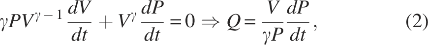
ANSI/(NFPA)T3.21.3 characterizes the volumetric flow rate Q (L/s) for charging and discharging through an orifice as,
30

For an actuator that is charging, by combining Eqs. (2) and (3), the flow rate and pressure of a constant pressure source charging an approximately constant volume load through an orifice is
30
:

While the valve flow conductance is a function of the pressure difference between the upstream and downstream paths and their absolute values, the following derivation aims to estimate the worst-case pressure resolution within the operating range of the actuator. By rearranging Eq. (4), the required flow coefficient

This is discussed in the section “Results.” Performance criteria of the system include a 10%–90% rise time ≤200 ms and an accuracy ≤2 kPa were first defined. Using Eq. (5), a resolution to 2 kPa and a minimum on-time of 20 ms, the valve conduction coefficient can be calculated
These values were used as starting points to select the orifice diameters of each valve. Second, simulations for a range of single orifices from 0.1 to 2.3 mm were performed to validate the response. This was then experimentally verified to show that the pressure resolution for a 0.35 mm orifice is 1.6 kPa, which agrees with the approximated prediction.
The large orifice was selected using the data, with an orifice of 0.9 mm diameter capable of achieving the 10%–90% rise in approximately 0.192 s.
Experimental System
The experimental system is illustrated in Figure 3 and comprises a diaphragm pump (Keyukang Electronic KYK50BPM 35 ), a 2 L air accumulator, four 2/2 on–off solenoid valves (SMC VDW22LA 29 ), two pressure sensors (Honeywell SSCDANV015PGAA5 36 ), and 6 mm tubing between each of these components. A custom manifold block shown in Figure 4 creates user-defined orifices for each valve. These manifold blocks are 3D printed on a Formlabs Form3 SLA printer in Grey Pro v4 resin. The manifolds were designed to limit the number of connectors required and minimize leakage. The pump and valves are driven by a PneuSoRD control board. 9 The hysteresis controller is implemented using MATLAB, Simulink, and dSPACE with a MicroLabBox.


Cross-section of the two orifice geometries. Left: Airflow through a single conventional orifice. Right: Airflow through a complex valve manifold orifice.
The experimental actuator follows the conventional molding procedure for soft fluidic elastomer robots.37,38 Molds are designed in Autodesk Fusion 360 and 3D-printed using a Voron Design Voron 2.4. Silicone rubber (DragonSkin 10) is mixed at a 1:1 ratio and degassed. The mixture is poured into the bottom mold, which is then clamped to the top mold. After 5 hours, the actuator is removed, and a strain-limiting layer (fiberglass fabric) is glued to the open side with a layer of DragonSkin. 9
Modeling and Simulation
A simulation model for the dual-valve system in Figure 3 was developed using Simscape Fluids and Simulink. As shown in Figure 5, the model includes a flow-rate source, accumulator, pipes, valves, and an actuator modeled by a constant volume. The simulation uses large orifice 2/2 on/off valves in series with smaller orifices to represent the experimental valves described in the section “Experimental System.” The ideal controlled volumetric flow source is set to a reference pressure of 100 kPa.
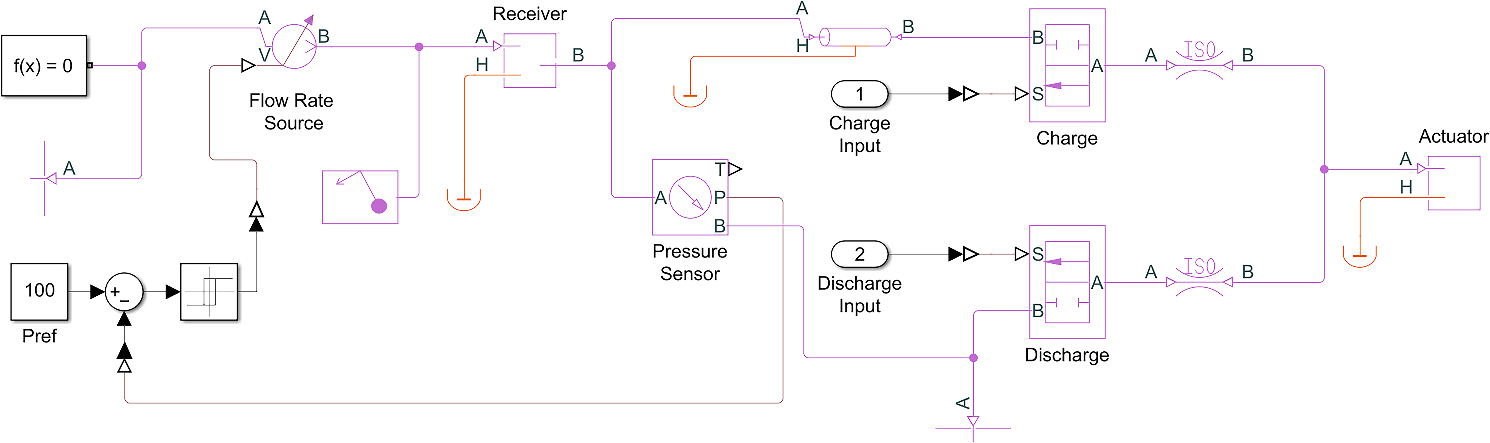
Simulink model of the pneumatic system. The pneumatic components are shown in magenta and include an air compressor modeled by a controlled volumetric flow source. Transmission pipes represent the pneumatic lines. A constant volume is used to model the actuator.
The simulation is used to evaluate the performance of the single-valve and dual-valve setups. Two measurements are taken from these results and used to characterize each orifice size. The first measurement is the rise time (10%–90%), which represents the actuation speed for large changes in pressure. The second measurement is the pressure change recorded 20 ms after the valve is opened, which represents the pressure resolution for a valve with a 20 ms minimum on-time.
Performing these simulations for a range of single orifices from 0.1 to 2.3 mm yields the results in Figure 6. Experimental results are also plotted in Figure 6, which show a similar trend. The difference between the simulated and experimental results is due to the geometric structure and flow coefficient variation between the simulated orifice and experimental orifice. The simulations allow the user to approximate the valve orifice size; however, to select the final valve requirements, experimental data should be used to select the required orifice.

Hysteresis Control
Hysteresis control is used to evaluate the performance of the proposed multivalve system in closed-loop. Hysteresis control allows a direct comparison of performance between a conventional single-valve system and the proposed multivalve system. For a system with single on/off valves, hysteresis control opens one valve at a time, since opening both valves causes direct discharge of pressurized air to the atmosphere. Eliminating this state reduces the number of possible states from 4 to 3. Figure 7A shows the logic output and limits of a symmetric hysteresis controller. When the pressure error exceeds (
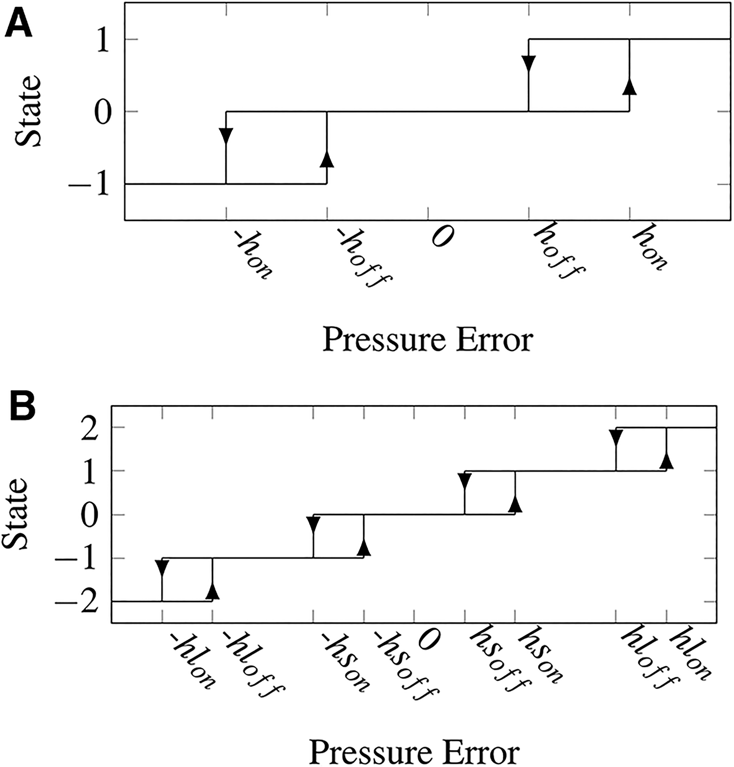
For a system with dual on/off valves, there are 16 possible states but only five useful states, which are: all valves off (0), slow charge (+1), fast charge (+2), slow discharge (−1), and fast discharge (−2). As shown in Figure 7B, this results in eight controller parameters, or four if they are chosen symmetrically.
Parameter selection
To avoid unnecessary valve activation, the hysteresis limits are chosen slightly greater than the pressure resolution, that is, the minimum achievable pressure change, over all operating conditions. From Eq. (4) the pressure resolution is approximately

Simulated Rise Time and Hysteresis Values for the Selected Orifices
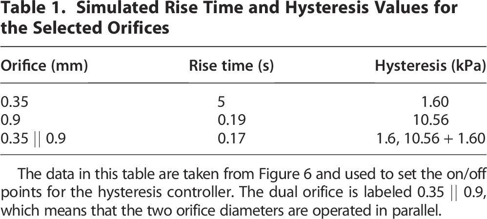
The data in this table are taken from Figure 6 and used to set the on/off points for the hysteresis controller. The dual orifice is labeled 0.35 || 0.9, which means that the two orifice diameters are operated in parallel.
To eliminate excessive switching due to measurement noise, the hysteresis limits are chosen slightly larger than the pressure resolution. In this article, a safety factor of 1.2 was selected for the on value of the hysteresis controller. That is:
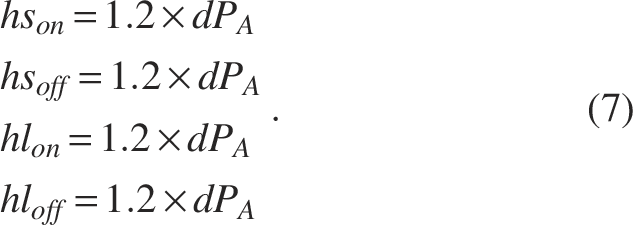
These safety factors were experimentally found to represent a good balance between pressure accuracy and erroneous switching events. Due to the stacked nature of the dual-valve hysteresis controller, the large valve off-time is different for the single and dual-valve controllers. With these safety factors applied, the hysteresis limits are:
Small valve on: Small valve off: Large valve on: Large valve off (single): Large valve off (dual):
Results
The experimental system is designed to achieve the following specifications:
10%–90% Rise time ≤200 ms Accuracy ≤2 kPa
The large orifice was selected using the data in Figure 6A. An orifice with a 0.9 mm diameter is capable of achieving the 10%–90% rise in approximately 0.192 s. This was repeated for the small orifice using the data in Figure 6B. A 0.35 mm orifice has a 20 ms pressure rise of 1.60 kPa; therefore, this was selected as the smaller orifice. In summary, the chosen orifice diameters are:
Small valve: 0.35 mm Large valve: 0.9 mm Dual valve: 0.35 mm || 0.9 mm
The notation 0.35 mm || 0.9 mm means that the two orifices are open in parallel. To determine the effectiveness of each controller and valve combination, a series of tests were conducted to compare the speed, accuracy, and ability to track dynamic references. The test conditions are described in the following, and the results are displayed in Figure 8. For each input test, the root mean square (RMS) error is calculated from:


Experimental comparison of the small-orifice single valve, large-orifice single valve, and dual-valve systems. The y-axis of each graph is the actuator pressure in kPa. Each column represents the experimental configuration tested, and each row represents a different test condition, which is discussed in the following: Speed—a full-range step input shows that the rise times of the large-orifice and dual-orifice systems are significantly faster than the small-orifice system, which is expected; Accuracy—a 2 kPa step demonstrates the ability of the small single-valve and dual-valve systems to track the desired 2 kPa pressure change; Large step—a series of decreasing-amplitude steps demonstrates that the dual-valve system simultaneously provides a fast rise time and high pressure accuracy; Small step—a series of 2 and 10 kPa step changes demonstrates that only the small-orifice and dual-orifice systems can track small changes in reference pressure; Dynamic—a sinusoidal wave increasing in frequency from 0.1 to 1 Hz over a 100 s period. The second axis zooms in on the interval from 0 to 50 s. The third axis zooms in on the interval from 60 to 80 s. All of the experiments demonstrate that the dual-valve system can simultaneously achieve the high speed of a large-orifice valve and the high resolution of a small-orifice valve.
Speed
The first row of Figure 8 compares the full step of 0–60 kPa for the three configurations under consideration. It can be observed that the single large orifice configuration has a faster response compared with the single small orifice configuration but a lower accuracy. The dual-valve response exhibits a comparable rise time to the large-orifice system and an accuracy similar to the single small-orifice system.
Accuracy
The second row of Figure 8 compares the ability of each configuration to resolve a 2 kPa step. The system with a single large orifice is unable to track the 2 kPa step, while the single small orifice and dual-valve configurations can track this reference change.
Large step response
The third row of Figure 8 compares the ability of each system to follow large step changes in reference pressure over a range of conditions. The pressure reference is a decreasing-amplitude square wave with a period of 10 s. The small valve system is incapable of settling before the input signal changes, resulting in a significant error. The dual-valve system shows the desirable characteristics of both the single small- and large-orifice systems; that is, the tracking performance is both fast and accurate.
Small step response
The small step response compares the ability of each system to follow a 2 kPa pressure change over a wide range of conditions. The small valve can track the step changes with minimal steady-state error. The system with only large valves is unable to track any of the desired step changes due to the larger required hysteresis band. The response of the dual-valve system is similar to the single small-orifice system.
Dynamic response
The fifth row of Figure 8 has a sinusoidal pressure reference increasing in frequency from 0.1 to 1 Hz over a 100 s period. The single small valve tracks the lower-frequency section of this input reference; however, as the frequency increases, the slew-rate limit eventually results in large tracking errors. On the other hand, the large valve performs best with the higher-frequency input. The lower-frequency signal is quantized by the large hysteresis band, while the dual-valve system combines these two benefits into a single response. A significant improvement over the entire range is shown.
Performance comparison
The RMS error for each experiment is summarized in Table 2. The dual-valve system is observed to consistently outperform the single small- and large-orifice systems. Further efforts could be made to include a negative source for improved deflation performance.
RMS Tracking Error of the Results Plotted in Figure 8

In each experiment, the dual-valve system matches or achieves a significant improvement in performance over the single-valve systems.
Comparison of valve configurations
Table 3 presents a comparison of different pneumatic valve configurations. While 3/2 valves are commonly used due to their affordability and ease of implementation, particularly in fluidic control boards, 2/2 valves offer notable advantages. These include lower energy consumption, reduced pressure fluctuations, and enhanced longevity due to fewer switching events, especially for constant pressure set points. Proportional valves, though more complex in terms of drive and control design, have not demonstrated a significant reduction in tracking error. 9 Consequently, a pneumatic system utilizing two 2/2 on–off valves is recommended for most applications.
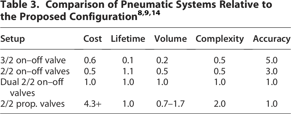
All valves have similar orifice diameters. Where possible, costs were sourced from the same manufacturer and supplier. Lifetime is assessed based on the number of valve switches required to achieve equivalent performance. Volume is estimated by considering the total setup size, including component connections within the system. Complexity is evaluated based on the electronic and control requirements for operating each configuration. Accuracy reflects the overall control performance across the three test signals.
Conclusion
This article describes a method for increasing the speed and accuracy of pneumatic soft robotic actuators. A dual-valve arrangement with optimized orifice sizes is proposed for the charge and discharge path. A design procedure is described for the orifice diameters and control parameters. A dual hysteresis controller, which allows independent tuning of the switching conditions for each orifice, was implemented to evaluate the performance of the proposed pneumatic system.
The proposed dual-valve system is experimentally compared with single-valve systems with a large and small orifice. The dual-valve system exhibits the high speed of large-orifice valves and the high resolution of small-orifice valves. Therefore, the proposed method provides a significant performance improvement for applications that require both high speed and resolution. This pneumatic system is best suited to tethered applications where large pressure sources and an increase in the number of valves do not negatively impact the function of the robot.
Applications are expected to include soft grippers, catheter devices, and soft robotic limbs, including fingers and hands. Future work will focus on optimizing the selection of valve orifice diameter and improving the control strategy for dynamic trajectories.
Footnotes
Author Disclosure Statement
No competing financial interests exist.
Funding Information
No funding was received for this article.