Quasi-Static Continuum Model with Fluid–Structure Interaction of an Octopus-Like Soft Robotic Arm Underwater Actuated by Twisted and Coiled Artificial Muscles
Open accessResearch articleFirst published online September, 2025
Quasi-Static Continuum Model with Fluid–Structure Interaction of an Octopus-Like Soft Robotic Arm Underwater Actuated by Twisted and Coiled Artificial Muscles
This study presents a qualitative investigation into the use of twisted and coiled artificial muscles (TCAMs) for actuating and replicating the bending motion of an octopus-like soft robotic arm underwater. The “extended” Cosserat theory of rods, alongside continuum mechanics principles, is employed to develop a strain-based model for the quasi-static motion of the soft arm, incorporating fluid–structure interaction through hydrostatic and dynamic forces from fluid flow. In the proposed model, the cross-section of the arm not only undergoes rigid rotation but also deforms within its plane, a feature that aligns with the biomechanical behavior of octopus arms, where local stiffness arises from the incompressibility of tissue. TCAMs, as lightweight and low-cost actuators, offer high power-to-weight ratios and can produce tensile forces up to 12,600 times their own weight, approaching the functionality of biological muscles. To support the modeling framework, a constitutive model is also developed to describe the characteristic material behavior of the soft octopus-like arm.
Early work on robot manipulation focused on discrete rigid manipulators, crafted to replicate the motion and grasping of the human hand.1 These robots consist of rigid links connected by joints, culminating in an end-effector that interacts with the environment. Therefore, each degree of freedom (DOF) relies on an actuatable joint, which limits the system’s agility. Consequently, enhancing maneuverability requires adding more joints and DOFs, increasing complexity in both design and control. Besides discrete robots, Robinson et al.2 categorized them into serpentine robots (also known as hyper-redundant manipulators) and continuum robots. Hyper-redundant manipulators typically feature a backbone structure with numerous actuatable joints, resulting in a DOF significantly greater than that of their operational workspace. For more details on modeling and solving the kinematics of hyper-redundant manipulators, see early works.3–5 They also employed the continuum formulation of kinematics to optimize the configuration of these manipulators.5 A continuum robot is a type of manipulator that can locally change its configuration at any point along its length.6 This allows it to navigate workspaces with obstacles and reach almost any point within them. Resembling the movements of snakes,7 elephant trunks,8 and octopus arms,9 continuum robots theoretically possess infinite DOFs. However, unlike other manipulators, not every DOF is actuated, resulting in a relatively small number of actuators generating the motion.8 These manipulators are typically actuated by cables, hydraulic, or pneumatic pressures.10–12
The analysis of motion in continuum robots is categorized into piecewise constant-field techniques8,13–16 and continuous-field techniques.17–22 One commonly adopted model for multi-sectional continuum robots is the piecewise constant curvature model, where it is assumed that the curvature remains constant along each section of the robot arm.8,13,14,16 The constant curvature technique becomes inaccurate in many scenarios, such as when significant external loads, like gravity, are present, or when there is considerable variation locally in the curvature of the robot arm.23,24 For more details on piecewise constant curvature model see.25
The standard Cosserat theory of rods,26 widely adopted as a continuous-field technique, offers an accurate formulation for the motion of continuum robots.17–22 This approach utilizes strain fields corresponding to the rod’s deformation to derive the dynamic motion of the robot arm. Previous works15,27 explains how standard Cosserat theory is implemented to model a cable-driven soft robot arm, followed by the application of the piecewise constant-strain technique for discretization.15 This approach was further developed in17 to incorporate a variable-strain methodology. Similarly, in,18 a strain-based technique was employed to construct a nonlinear parametrization of the Cosserat model for the soft robot arm and to conduct dynamic motion analysis. Unlike the standard Cosserat theory, which focuses solely on the deformation of the entire rod, the extended Cosserat theory of rods also incorporates planar deformation within the rod’s cross-section alongside the rod’s overall deformation.28 This implies that, the cross-section of the rod can undergo both rigid rotation and deformation within its plane. Incorporating the deformation in rod cross section can inherently enhance the dynamic analysis of the robot arm motion particularly for arms that undergo substantial deformations. For more details on application of Cosserat rod theory in modeling of continuum robots, see reviews.29,30
The recently developed twisted and coiled artificial muscles (TCAMs) offer lightweight and cost-effective alternatives to traditional actuators, such as electromagnetic motors, and hydraulic and pneumatic actuators.31–33 These artificial muscles generate a high power-to-weight ratio, producing tensile forces up to 12,600 times their own weight, closely resembling the functionality of biological muscles.34,35 The integration of TCAM actuators in soft robotics is rapidly growing due to their high power-to-weight ratio and low manufacturing cost.34 This application necessitates a thorough understanding and the development of a theoretical dynamic model of TCAMs to accurately describe their actuation behavior and facilitate the design of control algorithms. TCAM dynamics are categorized into fitting-based models, which derive constant parameters from experimental data, and physics-based models, utilizing constitutive relations.36 Weerakkody et al.36 developed a physics-based model akin to Giovinco et al.37 for TCAM actuation, introducing an adaptive control algorithm. This model extends their earlier static work in,38 comprising a thermal model linking input voltage or heat to fiber radius expansion in TCAMs, and a mechanical model describing how this radius expansion relates to generated tensile force in TCAMs. The extended Cosserat theory of rods has recently been employed in conjunction with continuum mechanics principles to develop a physics-based model of TCAMs for soft robotics applications,39 further demonstrating the applicability of this framework beyond classical rod systems. The proposed model is both more accurate and more general than previous models.37,38,40 The model is more general because it is strain-based, making the formulation applicable to different types of TCAMs with any geometry. This contrasts with previous geometry-based models, where the formulations explicitly depend on the TCAMs’ geometric configuration. Moreover, the model offers higher accuracy by incorporating nine strain components: three translational strains, three rotational (bending) strains of the bulk TCAM, and three cross-sectional strains. Unlike previous approaches, it does not rely on small deformation assumptions and allows for the incorporation of a nonlinear constitutive model to represent the TCAM’s material behavior. Therefore, the results demonstrate greater consistency compared to the standard Cosserat theory presented in.41
This work aims to investigate how hydrostatic and dynamic forces resulting from steady-state fluid flow influence the bending behavior of a soft robotic arm actuated by TCAMs. The modeling framework is based on the extended Cosserat theory of rods and is further supported by principles from continuum mechanics and fluid–structure interaction (FSI) to capture the interaction between the submerged arm and its surrounding fluid. This rod-based formulation allows for both rigid rotation and planar deformation of the cross-section, enabling a more accurate representation of soft structures with significant flexibility. While standard Cosserat rod theory accounts for rigid cross-sectional rotation, it assumes the cross-section remains rigid and undeformed.26 In contrast, the extended Cosserat formulation introduces in-plane deformation of the cross-section, which is essential for capturing the mechanics of hollow or highly deformable geometries such as octopus arms. This approach reflects the biomechanics of biological hydrostats, where localized stiffness arises from internal pressure and the incompressibility of the constituent tissue. The study explores the application of recently developed electro-thermo TCAMs, developed by some of the authors, to actuate and replicate the motion of octopus arms. A physics-based dynamic model of TCAMs is discussed to characterize their time-varying tensile actuation. Furthermore, a constitutive model is derived for the material of the octopus arm to capture its characteristic behavior.
Extended Cosserat Theory of Rods
Configuration of rod
Figure 1 shows both the reference (undeformed) straight configuration and the deformed configuration of the octopus-like arm, actuated by two longitudinal TCAMs. The extended Cosserat theory of rods28 is used to model the configuration of the robot arm. This theory retains the standard Cosserat framework, including all strains and governing equations that describe the bulk rod deformation, while adding new strains with corresponding equations to account for cross-sectional deformation. For a two-dimensional (2D) rod, this involves introducing a new normal strain to represent the planar deformation of the cross section, followed by the rigid rotation to determine the orientation of the cross section. The configuration of the robot arm, , is parametrized by the curve length of the centerline of the undeformed straight rod:
where represents the centerline of the rod, such that is the radius of undeformed rod (see Fig. 1a) and is the cross sectional normal strain that accounts for the planar deformation (i.e., stretching or compression) of the cross section along . The standard orthonormal directors and determine the rotation matrix , where form the global fixed Cartesian frame located on the centerline at and angle defines the orientation of (see Fig. 1b).
Octopus arm actuated by two TCAMs. TCAM, twisted and coiled artificial muscles.
Bulk strains
In standard Cosserat theory of rods, the bulk translational strains, which correspond to the deformation of the entire rod, are defined as the components of represented in the standard body frame
where and , respectively, measure the normal and shear translational bulk strains and subscript s signifies spatial derivative . Similarly, the bulk bending strains are defined as the components of and , expressed in the standard body frame:
where the bending strain locally measures the curvature of the centerline. The skew-symmetric matrix captures the bulk strains, where is the rigid body transformation. The centerline is calculated from strains by:
where and are its coordinates in standard body frame.
TCAMs Actuation Model
This section reviews the theory behind the recently developed electro-thermo TCAMs, by some of the authors.36 The theory consists of a thermal model and a mechanical model, which together describe the time-varying tensile actuation of TCAMs. The thermal model details the relationship between the input voltage or heat and the increase in the fiber radius in electro-thermally actuated TCAMs. The mechanical model relates the increase in fiber radius to the generated tensile force in the TCAMs.
Thermal model for TCAMs
TCAMs are manufactured by coating fibers with a thermally active polymer, then twisting them until they spontaneously coil. They undergo precise heat treatment to enable contraction when activated by electro-thermal stimuli. This contraction is caused by anisotropic volume expansion of the TCAM fibers after stimulation. The fibers’ anisotropic thermal properties cause their radius to increase upon exposure to heat, Joule heating, or absorption of a chemical solvent, while maintaining a constant length. For some materials like nylons, the fiber length shortens while the radius increases after stimulation.42 The increase in fiber radius can be linearly correlated with the rise in temperature:
where is the linear thermal expansion coefficient in the radial direction, denotes the initial fiber radius and is the change in temperature such that represents the ambient temperature. When the TCAMs are electro-thermally stimulated, the relationship between the input voltage and the change in temperature can be defined by:43
where represents time derivative and , and are respectively the thermal mass, electrical resistance, and the absolute thermal conductivity of the TCAM. Here, is the mass of the TCAM, is its cross section, is the convection coefficient between the actuator and the environment, and is the TCAM specific heat.
Mechanical model for TCAMs
The increase in the radius of TCAM fibers and the consequent anisotropic volume expansion of the fibers stiffen the bending and torsional deformations of the TCAMs, such that:
where are respectively normal Young’s modulus and shear modulus of TCAMs. The variation in bending and torsion stiffness of the TCAMs causes the change in the TCAMs geometry of coil angle
where denotes the total end rotation of the fiber, is the number of turns and denotes the external mass applied to the end of the TCAMs during the coiling process (the TCAM mass is neglected compared to mass ). Here, is the magnitude of gravity acceleration. The length of the TCAM after contraction is then calculated as:
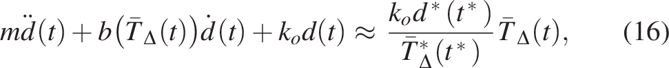
The dynamics of TCAMs actuation is modeled as a second-order mass-spring-damper system, governed by:
where , , and are, respectively, the time-dependent damping coefficient, the spring coefficient of the TCAMs, and the external force applied to the system. Considering an equilibrium configuration such that , where , then the time-dependent spring coefficient of the TCAMs is obtained:
The time-dependent damping coefficient of the TCAMs is calculated in correspondence to the viscosity coefficient of the TCAMs, where the Kelvin-Voigt viscoelastic theory is used to describe the constitutive behavior of the TCAMs as a viscoelastic material44
Now let us define the TCAMs contraction as , where the initial length of the TCAMs at time for ambient temperature of TCAMs is calculated as , where . The dynamic equation of motion of TCAMs (10) is reformulated:
where . Linearize (13) by considering , where the coefficient C can be experimentally approximated by some arbitrary constant temperature . Consider the equilibrium condition from (13) at an arbitrary time with arbitrary temperature and , where :
where such that is calculated from (11). Therefore, the coefficient C is:
and the dynamic equation of motion of the TCAMs is approximated as:
where is associated to the applied input voltage through the ODE in (6).
External and Internal Loads
Concentrated force of TCAMs
The concentrated force of the TCAMs of the segment is modeled as:45
where is the length of undeformed centerline of the segment and denotes the tension of the corresponding TCAMs and segment
In this context, the segment refers to an individual, flexible section of the arm that is actuated independently, allowing fine control over complex shapes. The temperature at any fixed time is associated to the applied input voltage through the ODE in (6). The for is the tangent vector to the TCAMs, such that the position vector of the TCAMs of the segment is determined by , where denotes the distance of that TCAMs from the undeformed centerline.
Distributed force of TCAMs
The distributed force per unit length of the TCAMs along the undeformed centerline of segment is modeled as:45
Therefore, the moment about the origin of the fixed global Cartesian frame is:
Fluid forces
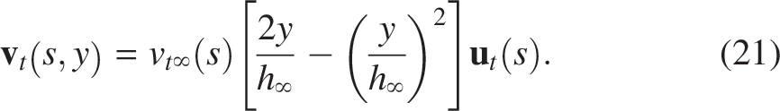
The primary objective is to investigate how hydrostatic and dynamic forces from a steady-state fluid flow affect the bending motion of an octopus-like robot arm propelled by TCAMs. Note that, the terms water and fluid are used interchangeably throughout this article. The article focuses on analyzing the static deformation of the arm as the tension in the TCAMs incrementally increases. To achieve this goal, a viscous fluid flow with a quadratic velocity profile is introduced over the arm. This velocity profile varies with the normal distance from the arm’s surface, satisfying the no-slip condition on the arm’s surface. The velocity monotonically increases to its maximum at a distance from the arm’s surface
The subscript t signifies the tangential direction to the surface of the arm such that is the tangent unit vector to the arm surface and is the tangential component of the free-stream velocity of the fluid flow. The quadratic velocity profile in (21) is used to calculate the viscous frictional force, given by , which acts on the infinitesimal (ventral or dorsal) surface of the arm, in the direction opposite to the flow on the surface :
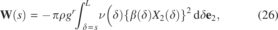
where is the dynamic viscosity of the fluid. The continuity equation and the principle of linear momentum for a steady state flow is applied separately over two infinitesimal control volumes of fluid on ventral and dorsal surfaces of the arm to compute the tangential and normal hydrostatic and dynamic contact forces applied by the fluid to the ventral and dorsal infinitesimal surfaces of the arm:
denotes the hydrostatic force of fluid, the superscripts V and D, respectively, signify the ventral and dorsal surfaces of the arm, subscript n signifies the normal direction to the surface of the arm, and subscript in signifies the inlet open surface of the control volume and its corresponding quantities. The weight of the infinitesimal control volume of the fluid is negligible compared with the other existing forces and therefore it is ignored in these computations. The normal component of the free-stream velocity is , where such that and forms an orthonormal local body frame of reference. The inlets and outlets of the control volume are determined in accordance with the direction of the velocity of the flow at each open surface of the control volume. The left and top surfaces of the control volume on the ventral surface of the arm serve as inlets, while the right surface is an outlet. Similarly, the left and right surfaces of the control volume on the dorsal surface of the arm are, respectively, an inlet and an outlet, with the flow through the top surface assumed to be negligible (see Fig. 1b).
In particular, the resultant normal force in (24), applied to the infinitesimal ventral surface of the arm, comprises both the hydrostatic force of the fluid and the dynamic force generated by the change in velocity (linear momentum) of the fluid flow between the inlet and outlet of the control volume from to 0. The resultant normal force in (25), applied to the infinitesimal dorsal surface of the arm, comprises only the hydrostatic force of the fluid, as the fluid flow through the top surface of the control volume is assumed negligible. The resultant tangential force in (23), applied to the infinitesimal ventral surface of the arm, consists of the force generated by the change in velocity (linear momentum) of the fluid flow between the inlet and outlet of the control volume from to . This indicates that the fluid flow exerts both hydrostatic and dynamic resultant forces on the surface of the arm, influencing the configuration of the deformed arm underwater. It is notable that the fluid forces in (22), (23), (24), and (25), along with their associated moments, are successively incorporated into the translational equilibrium equation (31) and the rotational equilibrium equation (32), presented in Section 6.
This modeling approach differs from classical frameworks such as resistive force theory (RFT) and slender body theory, both in formulation and application. Rather than estimating drag forces based on local velocity, as done in RFT, the present analysis employs a control volume framework grounded in the continuity and linear momentum equations for steady-state flow. The fluid domain is discretized into infinitesimal control volumes along the ventral and dorsal surfaces of the arm, where hydrostatic and dynamic forces are evaluated from depth and momentum changes across inlets and outlets. Importantly, the model captures both force and moment contributions from the fluid, including those due to viscous friction and dynamic pressure. These distributed moments are incorporated into the rotational equilibrium equation (32), thereby addressing the distributed drag couples mentioned in classical filament models, but through a different theoretical lens. While RFT is well-suited for long, slender filaments operating in low-Reynolds-number regimes, the approach adopted here is tailored to the geometry and actuation behavior of non-slender, soft, biologically inspired arms in steady-state flow. As such, the present model provides a complementary perspective that remains grounded in conservation laws while accounting for both hydrostatic pressure and dynamic momentum exchange in the fluid domain.
Weight of segment of arm
In the deformed configuration of the arm, the cross section is oriented along , and is not necessarily tangent to the centerline. Therefore, the weight of a segment of the deformed arm between is calculated as:
where denotes the density of the arm material. The normal strain appears in (26) to align the rod’s cross section with the direction of its centerline.
Resultant contact force and moment
The constitutive model of the soft robot material connects the strains to the internal contact forces and moments. Since the contact force is not always aligned with the normal unit director of the deformed cross section, it is expressed in the local standard body frame:
where , and N and H represent the normal and shear forces per unit area (tractions) of the cross section, which correspond to the normal and shear strains and , respectively. The constitutive model of the arm material defines the resultant contact moment in the local standard body frame as:
where M is proportional to the magnitude of the bending moment and corresponds to the bending strain (local curvature) . is the second moment of inertia of the circular cross section of the rod about axis.
Constitutive Model
The behavior of the soft material of the robot arm is described by a hyperelastic model. In a hyperelastic material, the stress field is a conservative function derived from a scalar-valued function called the strain energy function, by taking its derivative with respect to the strain field. Let’s assume the strain energy function for the robot arm is a quadratic polynomial of bulk strains:
where , and respectively denote the normal, shear and bending stiffness coefficients of the arm material. The constitutive equations for a continuum material must meet specific criteria to accurately model its behavior. The strain energy function needs to be sufficiently smooth as the quadratic polynomial in (29) is infinitely continuously differentiable , assuming for . In this work, the reference (straight) configuration of the rod is defined as an undeformed configuration where all bulk and cross-sectional strains vanish. It is also intended that the natural (stress-free) configuration coincides with the reference configuration, ensuring the strain energy function is minimized, thereby causing stress to vanish. Consequently, the straight reference configuration aligns with both the undeformed and stress-free configurations, resulting in vanishing strains and stresses. The tractions are required to monotonically increase. This implies that any increase in bulk strains , , and induces an increase in the corresponding tractions , , and , such that each traction reaches its maximum at the maximum of the respective bulk strain. The following constitutive equations are proposed here for these tractions based on the necessary conditions required for the strain energy function
where and . F∈or an isotropic material, the Young’s modulus E and the shear modulus G are related by , where is the Poisson’s ratio. It is notable that since , , and in (30) monotonically increase, they are injective and invertible functions. This implies the existence of conjugate constitutive fields , , and .
Governing Equations for Bulk Strains
To derive the governing equations for the system, the translational and rotational equations of equilibrium are utilized in their local forms. This results in three scalar-valued governing equations for the bulk strains , , and . These equations are formulated as a system of three nonlinear ordinary differential equations (ODEs). The vector form of the governing equations is expressed as follows:
where using (19), (22), (23), (24), (25), and (27). Here, is the weight of the arm per unit length of straight centerline, which is obtained from (26). For (32) use (20) and (28), where and denotes the moment of the arm’s weight in (26) about the origin of the fixed global Cartesian frame.
Local Volume Preservation Constraint
The current work applies the extended Cosserat theory of rods to a 2D rod, where the planar deformation of the rod’s cross section is characterized by a single cross-sectional normal strain, . This is consistent with the framework in,28 where for a three-dimensional (3D) rod, the planar deformation of its cross-section is described using two normal and one shear strain fields. However, the formulation presented here for modeling the octopus-inspired soft arm, based on Cosserat rod theory and accounting for cross-sectional deformation, differs slightly in structure. While Kumar and Mukherjee28 derive the additional governing equations for cross-sectional deformation using equation of motion and continuum mechanics principles in the 3D setting, the current work formulates the governing equation for planar cross-sectional deformation based on the continuum mechanics principle of locally volume-preserving deformation. This approach is biologically motivated, as the incompressibility of tissue in muscular hydrostats, such as octopus arms, significantly influences the mechanical stiffness of the hydrostat. This means that, the deformation of the octopus arm is locally constrained by:
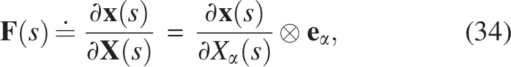
where V and v are respectively the volumes of undeformed and deformed robot arms and denotes the deformation gradient tensor:
where describes the straight arm, and for and denotes the tensor product of two vectors. Note that the summation convention is used over the repeated index in (34). Using (1), (2), (3), and (34), the local volume preservation constraint in (33) yields a governing equation for the new cross-sectional normal strain :
Note that the local volume preservation constraint in (33) is satisfied only by the strain in (35), without any corresponding internal force or moment associated with . This contrasts with scenarios where the local volume preservation constraint is enforced on the strain energy function using a Lagrange multiplier, such as pressure (stress). In that case, there is no strain directly conjugate to the pressure, meaning the pressure is not computed through a constitutive equation.
Results and Discussion
In this section, we apply the previously discussed general formulations to a specific case study. This case study focuses on an octopus-like soft robot arm with a straight undeformed configuration and a truncated conic geometry that is characterized by a radius of (see Fig. 1a):45
such that denote the maximum and minimum radii of the undeformed rod cross sections, respectively. The distance of the TCAMs in segment from the undeformed centerline is calculated as:
where such that and represent the distances of each TCAM in segment from the undeformed centerline of the rod successively at the beginning and end of that segment. In this setup, electro-thermo carbon fibers/silicone rubber TCAMs are employed to actuate the octopus robot arm. These TCAMs are driven by a sinusoidal input voltage , where is the amplitude and rad/second is the angular frequency. Table 1 tabulates the parameters of these TCAMs.40 It is notable that, the material parameters used in this study, such as Young’s modulus and electrical resistance, are constitutive characteristics associated with the models presented in Sections 3 and 5, which describe the mechanical behavior of the soft robotic arm under external loading due to TCAM actuation and fluid flow. These coefficients, along with other physical constants, can be easily adjusted within the dynamic model to represent different soft materials or fluid types. In this work, representative values were selected for a specific case study to demonstrate the formulation and effectiveness of the proposed ODE-based dynamic modeling framework. The primary objective was to develop a general model and algorithm for simulating the motion of soft robotic arms under the influence of fluid flow, and to validate the modeling approach. Therefore, a detailed parametric study was not conducted. However, the model is formulated in a general way and can be readily applied to systems with different material or fluid properties, depending on the specific use case or design requirements.
Parameters of TCAMs
Parameters
Values
0.106 Kg
0.106 Kg
0.46 m
0.418 m
200
m
23
0.162
18
Pa
Pa
0.0086
Results
Figure 2a shows that the temperature of the electro-thermo TCAMs, stimulated by the sinusoidal voltage, rises to . Correspondingly, the TCAMs’ tensile force in Figure 2b increases similarly, reaching 25 N. It is important to note that the functionality of the TCAMs is highly dependent on temperature, with potential malfunctions occurring beyond a certain threshold. Figure 2a indicates that the TCAMs are operating within a feasible temperature range. The system of four coupled nonlinear ODEs (31), (32), and (35) forms a quasi-static model. This model is used to study the effects of hydrostatic and dynamic forces from steady-state fluid flow on the bending motion of an octopus-like robot arm driven by TCAMs. The deformed configuration of the arm is analyzed statically at each incremental increase in the tension of the TCAMs. The model is numerically solved for the four unknown strain fields: normal strain , shear strain , bending strain , and cross-sectional normal strain , under the boundary conditions (BCs) for the fixed support arm: and . In this section, the application of the model to two case studies involving free-stream velocities m/s and 0.4 m/s of steady-state water flow is presented. For each case study, a step size of 0.5 N is used to incrementally increase the tension N of the TCAMs, allowing for a static analysis of the arm’s deformation under water at each tension level. The parameters and dimensions for both case studies are provided in Table 2. Figure 3 illustrates the deformations of the arm for various tensions N applied by the TCAMs and for two water free-stream velocities, m/s and 0.4 m/s. The direction of the tangent vector in (2) to the centerline of the arm at , and the direction of the unit director at , are displayed on each configuration of the rod in both Figure 3a and 3b. It is notable that traditional rod theories do not account for any deformation or rigid rotation of the cross-section. Consequently, the cross section at any always remains perpendicular to the tangent line of the centerline. In other words, the tangent vector in Figure 3 signifies the orientation of the cross section of the rod at , before any rigid rotation. On the other hand, in the standard Cosserat theory of rods, the unit director is defined such that it always remains perpendicular to the cross-section of the rod through deformation and signifies the orientation of the cross section after rigid rotation. Therefore, each unit director in Figure 3 shows the orientation of the rotated cross-section at for the corresponding configuration.
(a) TCAMs temperature and (b) TCAMs tensile force, both actuated by a sinusoidal voltage.
Deformations for various tensions of TCAMs N and water free-stream velocities m/s.
Parameters of Silicone Rubber and Water
Parameters
Values
10 MPa
0.5
1.1
9.81
4 mm
15 mm
418 mm
12 mm
1 mm
0.998
1.002 mPa.s
0.2, 0.4 m/s
[0, 20] N
0.0 N
Figure 3 demonstrates that as the tension of the TCAMs increases, the overall deformation of the arm gradually amplifies. This is observed in both scenarios of water free-stream velocities: (Fig. 3a) and (Fig. 3b). Specifically, at , the tip of the arm reaches heights of cm and 10.56 cm, respectively, for these velocities under the constant tension N. This implies that for the same tension , the overall deformation of the arm, measured by the height of its tip at , is less pronounced at higher water free-stream velocities. This reduction in bulk deformation is primarily attributed to the effects of drag force and the dynamic forces exerted by the water flow on the arm’s surface, where both the drag force and resulting dynamic force are proportional to the square of the flow velocity. The dynamic force in a steady-state flow results from changes in linear momentum (velocity vector) within the fluid’s control volume between two open surfaces. This alteration in momentum does not solely stem from friction between the arm’s surface and the water, as it can occur even in the flow of an inviscid fluid over a frictionless body surface. Figure 3c visually compares the bulk deformation of arm configurations under the constant tension of TCAMs N for two scenarios: water free-stream velocities and . This comparison underscores that, when subjected to the same tension , the arm experiences less deformation at higher free-stream flow velocities.
Figure 4a illustrates the variation of the tilt angle, , of the rod’s cross section at (see Fig. 1b) across tensions of TCAMs N, for water free-stream velocities and . From Figure 1b, and , respectively, signify the orientations of the cross section before and after the rigid rotation of the cross-section. In essence, depicted in Figure 4a indicates how much the cross-section deviates from its original perpendicular orientation due to the rod’s deformation. Figure 4a demonstrates that in the straight arm, the tangent vector aligns with the unit director (see Fig. 3a and 3b) for both water free-stream velocities. Figure 4a illustrates that is consistently positive for both and m/s across all TCAMs tensions N. This implies algebraically, indicating a clockwise tilt of the rod’s cross section at every tension and for both water velocities. The clockwise rotation is visually confirmed by the orientations of and in Figures 3a and 3b. The orientation of the cross section at is influenced by two primary factors: 1) the difference in curvatures between the ventral and dorsal surfaces of the rod, and 2) the concentrated force exerted by the TCAMs as defined in (17). For TCAM tensions N and N, which produce counterclockwise bent configurations as seen in Figures 3a and 3b, the curvature of the ventral surface at any point is generally greater than or equal to the curvature of the dorsal surface at the same point . The cumulative effect of these local curvature differences along the ventral and dorsal surfaces drives the clockwise rotation of the cross section at , as depicted in Figure 3. The initial increase in the tilt angle shown in Figure 4a is attributed to the heightened curvatures of the ventral and dorsal surfaces of the arm for higher TCAM tensions. This results in increasing differences in local curvatures, consequently leading to a larger tilt angle at . Conversely, the decreasing trend of the tilt angle, observed at N for m/s and at N for m/s, is driven by the increasing concentrated force of the TCAMs . This concentrated force induces a counterclockwise rotation in the cross-section at , opposing the clockwise rotation caused by the curvature differences along the ventral and dorsal surfaces. Figure 4a illustrates that the tilt angle reaches larger values for a water free-stream velocity of m/s compared with m/s, under the same tensions . This accelerated increase in tilt angle can be attributed to the faster growth of angle observed at m/s, as shown in Figure 4b. Figure 4c displays the variation of the tilt angle along the arm for selected tensions N and at m/s. The positive tilt angle implies clockwise rotation of the cross section along the arm. Note that, the downward trend near the rod’s end is influenced by the increasing concentrated force of TCAMs at higher tensions.
Variations of angles , , and cross-sectional strain .
The variation of the cross-sectional normal strain along the arm is depicted in Figure 4d for various tensions N under a water free-stream velocity of . represents the planar deformation of the cross-section in the direction of the standard unit director . This deformation enables the arm’s cross-section to adjust locally while preserving the local volume. This behavior aligns with the biomechanical principles observed in octopus arms, where tissue stiffness depends on incompressibility. Figure 4d indicates that increases monotonically along the arm for all tensions . In the present work, is introduced as a normal strain in the direction of the director within the extended Cosserat theory of rods in two dimensions. Unlike standard Cosserat rod theory, which assumes a rigid, undeformable cross-section, the extended theory permits planar deformation of the cross-section, which is essential for capturing the local mechanical response of soft materials. In this 2D setting, describes how the initially circular cross-section undergoes uniform radial deformation, becoming either a larger or smaller circle depending on whether or . The director lies in the plane of the cross-section and defines its local orientation. The second director, , is orthogonal to and represents the outward normal direction from the cross-section. Importantly, is not necessarily aligned with the tangent to the centerline (except in the undeformed state). Instead, it is tilted by an angle , where is the angle between the centerline tangent and the global horizontal axis, and is the angle between and the same axis (see Fig. 1b). Physically, controls not only the deformation of the cross-section but also affects the bending stiffness of the rod. This is because bending stiffness is directly related to the second moment of area (also known as the area moment of inertia) of the cross-section. For a circular cross-section of undeformed radius , the second moment of area is given by When the cross-section deforms under the influence of , its new radius becomes , and the updated second moment of area becomes Thus, the bending stiffness of the rod scales with , meaning that even small changes in can have a significant impact on local bending resistance. When , the cross-section enlarges and the bending stiffness increases; when , the cross-section shrinks and the bending stiffness decreases. This provides a biologically inspired mechanism for local stiffness modulation along the soft arm, much like what is observed in octopus limbs that adjust shape to support different motion strategies. To further explore arm mechanics, Figure 5 illustrates the variations in the normal and shear tractions, as well as the bending moment along the arm for selected TCAM tensions.
Normal traction , shear traction , bending moment , and bending stiffness along the rod for various TCAM tensions and water free-stream velocity .
Figure 5d shows the variation of bending stiffness along the soft robotic arm for a representative case with maximum TCAM tension of and water free-stream velocity of . As illustrated in Figure 1a, the undeformed shape of the arm is a truncated cone with a larger cross-sectional radius near the base () and a smaller radius near the tip (). At this actuation level, the cross-sectional normal strain increases monotonically along the arm, as shown in Figure 4d, indicating local expansion of the cross-section toward the tip. However, because the undeformed radius decreases along the arm, the geometric reduction dominates the strain-induced expansion, leading to an overall decrease in bending stiffness from to . This decreasing stiffness results in a corresponding increase in the curvature along the arm under TCAM actuation (see Fig. 3), causing more pronounced bending near the tip. Interestingly, while the stiffness decreases, the curvature increases more sharply, leading to an increase in bending moment along the arm, as illustrated in Figure 5c. This observation highlights a key feature of soft continuum structures actuated by internal artificial muscles: even with decreasing stiffness toward the tip, bending moments can intensify due to the combined effects of geometry and curvature amplification.
Validation
The physics-based (geometry-based) model for the dynamics and actuation of TCAMs used in this work was previously developed and experimentally validated using actuation data from three different experimental setups: (1) constant stress, (2) constant strain, and (3) dynamic force configurations, for both CF/PDMS and nylon fishing-line TCAMs.36,38 In addition, the authors have recently developed a novel strain-based model for TCAM actuation, grounded in extended Cosserat theory,39 which has been experimentally validated for both CF/PDMS and nylon fishing-line TCAMs under a constant stress configuration. However, neither the geometry-based nor the strain-based models have yet been applied in the context of soft robotic arm actuation. The current work focuses on this direction by integrating TCAMs into soft robotic structures to generate dynamic arm configurations using TCAM-based actuation. Therefore, this study emphasizes simulation-based validation of soft robotic motion actuated by TCAMs. Future work will incorporate experimental testing and two-way FSI analysis to validate the dynamic underwater motion of TCAM-actuated soft robotic arms against experimental data.
To validate the Cosserat-based model for the octopus-like arm in water, Ansys simulations were conducted under similar conditions. Due to the limitations of beam elements in Ansys for FSI analysis, 3D solid elements were utilized, and an FSI approach was employed to accurately model the interaction between the soft arm and the steady-state water flow. Figure 6 shows the deformations of the arm modeled in Ansys with FSI, while Figures 7 and 8, respectively, present the distribution of velocity and pressure fields over the arm. The Ansys simulation results generally show strong agreement with the Cosserat-based model, particularly in terms of the maximum deformations at the arm tip, confirming the model’s accuracy. However, some discrepancies are observed at the arm tip, where the Ansys results differ in curvature compared with the Cosserat-based results. This divergence arises because the extended Cosserat theory models the arm as a rod, effectively capturing the complex behavior of the arm’s curvature and the orientation of its cross-section, which are particularly critical at the tip where curvature is more pronounced. In contrast, the 3D solid elements in Ansys do not explicitly model the arm’s curvature as a rod or the orientation of the cross-section, leading to variations in predicted curvature and overall deformation, especially in regions with higher curvature. This difference in modeling approaches explains the observed discrepancies, particularly at the arm’s tip.
Deformations of the arm modeled in Ansys with FSI for different flow velocities. FSI, fluid–structure interaction.
Distribution of the velocity fields over the arm for different flow velocities.
Distribution of the pressure fields over the arm for different flow velocities.
Conclusions
This study investigated the use of recently developed TCAMs to actuate and replicate the bending motion of an octopus-like soft robotic arm underwater. A quasi-static continuum model was developed using FSI principles to examine the effects of hydrostatic and dynamic forces from steady-state fluid flow on the arm’s bending behavior. The extended Cosserat theory of rods, combined with continuum mechanics principles, was employed to model the soft arm as a continuum robot, allowing for rigid rotation of the cross-section without constraining it to remain locally normal to the rod’s centerline. In contrast to the standard Cosserat theory, the extended framework includes planar deformation of the cross-section by introducing a new normal strain field to capture in-plane deformation. A constitutive model for the octopus arm material was also proposed to capture its characteristic behavior. While this study adopts a simplified thermal-mechanical model assuming constant material properties, it is acknowledged that temperature-dependent variations in material behavior may affect model accuracy under high temperatures or fast actuation. Incorporating these effects, guided by prior experimental studies,36,38 will be an important direction for future work to improve the fidelity of TCAM actuation modeling in dynamic or thermally varying conditions. The steady-state fluid flow considered in this study assumes that the velocity and momentum of the flow are independent of time, that is, they do not vary with time at any given point within the control volume. However, they may still vary spatially from point to point. The steady-state assumption, which is a rational and widely used simplification in many case studies, refers strictly to the temporal invariance of flow properties and does not imply any assumptions regarding whether the flow is laminar, turbulent, or subject to transient effects. The adopted modeling approach provides a general framework for evaluating fluid effects on the structure and is independent of the specific flow velocity or regime. In other words, the technique used here to calculate the effects of fluid flow on underwater robotic motion is broadly applicable to flows of various types and velocities. However, we acknowledge that this formulation does not capture transient effects, flow separation, or turbulence. These phenomena could introduce additional unsteady FSI forces. Addressing them through two-way coupled FSI simulations will be a key direction for future work to further enhance the fidelity of the model in dynamic underwater environments.
Footnotes
Abbreviations
References
1.
GullettaG, ErlhagenW, BichoE. Human-like arm motion generation: A review. Robotics, 2020; 9(4):102.
2.
RobinsonG, DaviesJBC. Continuum robots—a state of the art. In: Proceedings 1999 IEEE International Conference on Robotics and Automation (Cat. No. 99CH36288C), vol. 4. IEEE; 1999, pp. 2849–2854.
3.
ChirikjianGS. Theory and Applications of Hyper-Redundant Robotic Manipulators. PhD thesis, California Institute of Technology; 1992.
4.
ChirikjianGS, BurdickJW. A modal approach to hyper-redundant manipulator kinematics. IEEE Trans Robot Automat, 1994; 10(3):343–354.
TrivediD, RahnCD, KierWM, WalkerID. Soft robotics: Biological inspiration, state of the art, and future research. Appl Bionics Biomech, 2008; 5(3):99–117.
HannanMW, WalkerID. Kinematics and the implementation of an elephant’s trunk manipulator and other continuum style robots. J Robot Syst, 2003; 20(2):45–63.
9.
LaschiC, MazzolaiB, MattoliV, et al.Design of a biomimetic robotic octopus arm. Bioinspir Biomim, 2009; 4(1):e015006.
10.
RendaF, LaschiC. A general mechanical model for tendon-driven continuum manipulators. In: 2012 IEEE International Conference on Robotics and Automation. IEEE; 2012, pp. 3813–3818.
11.
MarcheseAD, TedrakeR, RusD. Dynamics and trajectory optimization for a soft spatial fluidic elastomer manipulator. In: 2015 IEEE International Conference on Robotics and Automation (ICRA). IEEE; 2015, pp. 2528–2535.
12.
RusD, TolleyMT. Design, fabrication and control of soft robots. Nature, 2015; 521(7553):467–475.
13.
KatzschmannRK, SantinaCD, ToshimitsuY, et al.Dynamic motion control of multi-segment soft robots using piecewise constant curvature matched with an augmented rigid body model. In: 2019 2nd IEEE International Conference on Soft Robotics (RoboSoft). IEEE; 2019, pp. 454–461.
14.
SantinaCD, KatzschmannRK, BiechiA, RusD. Dynamic control of soft robots interacting with the environment. In: 2018 IEEE International Conference on Soft Robotics (RoboSoft). IEEE; 2018, pp. 46–53.
15.
RendaF, BoyerF, DiasJ, SeneviratneL. Discrete cosserat approach for multisection soft manipulator dynamics. IEEE Trans Robot, 2018; 34(6):1518–1533.
16.
SayadiA, CecereR, HooshiarA. Finite arc method: Fast-solution extended piecewise constant curvature model of soft robots with large variable curvature deformations. Robot Rep, 2024; 2(1):49–64.
17.
RendaF, ArmaniniC, LebastardV, et al.A geometric variable-strain approach for static modeling of soft manipulators with tendon and fluidic actuation. IEEE Robot Autom Lett, 2020; 5(3):4006–4013.
18.
BoyerF, LebastardV, CandelierF, RendaF. Dynamics of continuum and soft robots: A strain parameterization based approach. IEEE Trans Robot, 2021; 37(3):847–863.
19.
XunL, ZhengG, KruszewskiA. Cosserat-rod-based dynamic modeling of soft slender robot interacting with environment. IEEE Trans Robot, 2024; 40:2811–2830.
20.
RoshanfarM, DargahiJ, HooshiarA. Cosserat rod-based dynamic modeling of a hybrid-actuated soft robot for robot-assisted cardiac ablation. Actuators, 2023; 13(1):8.
21.
DoroudchiA, BermanS. Configuration tracking for soft continuum robotic arms using inverse dynamic control of a cosserat rod model. In: 2021 IEEE 4th International Conference on Soft Robotics (RoboSoft). IEEE; 2021, pp. 207–214.
22.
TillJ, AloiV, RuckerC. Real-time dynamics of soft and continuum robots based on cosserat rod models. Int J Robot Res, 2019; 38(6):723–746.
23.
CamarilloDB, MilneCF, CarlsonCR, et al.Mechanics modeling of tendon-driven continuum manipulators. IEEE Trans Robot, 2008; 24(6):1262–1273.
24.
TatliciogluE, WalkerID, DawsonDM. New dynamic models for planar extensible continuum robot manipulators. In: 2007 IEEE/RSJ International Conference on Intelligent Robots and Systems. IEEE; 2007, pp. 1485–1490.
25.
WebsterRJIII, JonesBA. Design and kinematic modeling of constant curvature continuum robots: A review. Int J Robot Res, 2010; 29(13):1661–1683.
26.
AntmanSS. Nonlinear Problems of Elasticity. Springer; 2005.
27.
GiorelliM, RendaF, CalistiM, et al.A two dimensional inverse kinetics model of a cable driven manipulator inspired by the octopus arm. In: 2012 IEEE International Conference on Robotics and Automation. IEEE; 2012, pp. 3819–3824.
28.
KumarA, MukherjeeS. A geometrically exact rod model including in-plane cross-sectional deformation. J Appl Mech, 2011; 78(1).
29.
QinL, PengH, HuangX, et al.Modeling and simulation of dynamics in soft robotics: A review of numerical approaches. Curr Robot Rep, 2023; 5(1):1–13.
30.
ArmaniniC, BoyerF, MathewAT, et al.Soft robots modeling: A structured overview. IEEE Trans Robot, 2023; 39(3):1728–1748.
31.
LengX, HuX, ZhaoW, et al.Recent advances in twisted-fiber artificial muscles. Advanced Intelligent Systems, 2021; 3(5):2000185.
32.
YangSY, ChoKH, KimY, et al.High performance twisted and coiled soft actuator with spandex fiber for artificial muscles. Smart Mater Struct, 2017; 26(10):105025.
33.
TawfickS, TangY. Stronger artificial muscles, with a twist. Science, 2019; 365(6449):125–126.
34.
SaharanL, TadesseYT. Novel twisted and coiled polymer artificial muscles for biomedical and robotics applications. In: Materials for Biomedical Engineering. Elsevier; 2019, pp. 45–75.
WeerakkodyTH, HammondM, NeilanJH, et al.Modeling and control of twisted and coiled artificial muscles for soft robotics. Meccanica, 2023; 58(4):643–658.
37.
GiovincoV, KotakP, CichellaV, et al.Dynamic model for the tensile actuation of thermally and electro-thermally actuated twisted and coiled artificial muscles (TCAMS). Smart Mater Struct, 2020; 29(2):e025004.
38.
LamutaC, MesselotS, TawfickS. Theory of the tensile actuation of fiber reinforced coiled muscles. Smart Mater Struct, 2018; 27(5):e055018.
39.
Fahim GolestanehA, CichellaV, LamutaC. Physics-based modeling of twisted and coiled artificial muscles (tcams) for soft robotics using extended cosserat theory of rods. Smart Mater Struct, 2025; 34(4):e045015.
40.
HammondM, CichellaV, WeerakkodyT, LamutaC. Robust and adaptive sampled-data control of twisted and coiled artificial muscles. IEEE Control Syst Lett, 2022; 6:1232–1237.
41.
SunJ, ZhaoJ. Physics-based modeling of twisted-and-coiled actuators using cosserat rod theory. IEEE Trans Robot, 2022; 38(2):779–796.
42.
HainesCS, LimaMD, LiN, et al.Artificial muscles from fishing line and sewing thread. Science, 2014; 343(6173):868–872.
43.
YipMC, NiemeyerG. High-performance robotic muscles from conductive nylon sewing thread. In: 2015 IEEE International Conference on Robotics and Automation (ICRA). IEEE Press; 2015, pp. 2313–2318.
44.
KatoA, HirabayashiM, MatsurnotoY, et al.Continuous wrist joint control using muscle deformation measured on forearm skin. In: 2018 IEEE International Conference on Robotics and Automation (ICRA). IEEE Press; 2018, pp. 1818–1824.
45.
RendaF, GiorelliM, CalistiM, et al.Dynamic model of a multibending soft robot arm driven by cables. IEEE Trans Robot, 2014; 30(5):1109–1122.