
Abstract
Photovoltaic systems are attractive renewable energy sources for rural electrification and distributed power generation. However, the capital cost of these systems compared to non-renewable energy sources is still challenging. Thus, many researchers have focused on enhancing the efficiency and feasibility of PV systems. This paper proposes an optimum methodology for optimizing the layout of power distribution network for grid-connected photovoltaic systems considering solar inverter size and location, as well as cable path. The main aim of the proposed method is to offer the shortest cable length and path; achieving a higher efficiency and feasibility in the overall assessment. The suggested approach follows a heuristic method, starting by generating numerous inverter combinations for analysis. For each combination, the total length of cables is calculated considering all feasible inverter locations, aided by Python code to ensure precision. Ultimately, the method identifies the optimal inverter location that results in the shortest cable lengths. A 900 kWp grid-connected photovoltaic system is chosen as a case study in this research. Results show that a 26.9% reduction in total cable length as compared to the conventional approach is achieved by the proposed method. Meanwhile, the proposed method offered a better configuration of required solar inverters (size and location). Such a method is very useful for designing photovoltaic systems AC and DC distribution networks and exceeds the conventional and intuitive methods.
Introduction
Photovoltaic (PV) systems are one of the most common renewable energy sources (Khatib et al., 2016). Although PV systems are known to be clean, environmentally friendly, and secure energy sources, the capital cost of these systems as compared to non-renewable energy sources is still considered high. Thus, when designing a grid-connected PV system, designers should carefully consider the proper size of the PV array and inverter, the optimum size of the AC and DC distribution network (length, size, and distribution), shading impact, adherence to local regulations and grid requirements, and many other factors (Khatib et al., 2016).
The AC power distribution network in a PV system consists of three types of cables, which are DC, AC, and earthing cables. The DC cables connect the PV arrays to the inverter, while the AC cables are used to link the inverters to the electricity grid either directly or via a power transformer. Meanwhile, earthing cables are AC cables that are used to earth all of the parts of the PV system. PV system's power distribution network needs to be sized correctly to enhance the reliability and the performance of the system, hence, reducing the cost (Ekici and Kopru, 2017).
According to (Reichelstein and Yorston, 2013), more than half of the PV system costs are attributable to balance-of-system (BoS) components which include the inverter and the wiring system. Therefore, it is necessary to reduce these costs to increase the feasibility of the PV system. The cost of system wiring depends on the PV system layout's complexity, the length, and the gauge of the wires. A significant portion of the system installation budget may be allocated to the wiring costs because cabling is necessary to link all of the components and to ensure efficient electrical flow. Thus, cutting back on wiring expenses can help lower the PV system's overall cost and increase its economic viability (Reichelstein and Yorston, 2013). Based on that, many authors focused on the importance of designing the cables to provide a higher efficiency for the overall PV system, whereas an optimum power distribution network can decrease losses and increase the expected productivity of the PV system (Narasimhan, 2020).
The efforts of optimizing the PV system power distribution network can be divided into two categories; which are the optimization of solar inverter size, and the optimal design of the power distribution network (wire's length, configuration, and size). For solar inverter size optimization, many authors have utilized meteorological data and PV system models to find the optimum solar inverter size that assures maximum conversion efficiency. In (Notton et al., 2010) the authors proposed a method for optimal selection of solar inverter size considering specific locations. Similarly, In (Demoulias, 2010), a method was introduced to determine the most suitable inverter size, energy yield, and efficiency for grid-connected PV power plants in different geographical locations. The approach involves considering crucial factors that impact the performance of these power plants and employs a simple yet effective technique to select the appropriate inverter. In addition, in (Chen et al., 2013) an optimization method was proposed to select the optimum inverter size for PV grid-connected power plants. The method considered various factors, including solar irradiance, temperature, wind speed, component specifications, and location characteristics.
In most of the previously mentioned research, the authors have focused on the optimal sizing of solar inverters without considering AC and DC networks layouts. However, according to (Gan et al., 2014), a saving of 50% may be achieved in the photovoltaic system's Wp cost when optimally considering the design of “other system materials”, including wiring configurations.
Based on that, some other researchers have focused on the optimal design approach of AC and DC wiring in photovoltaic systems. In (Ekici and Kopru, 2017) the authors used commercial software to simulate a PV system to find the optimum value for cable cross-sectional area by considering power losses, and economical operational factors. However, the authors didn’t consider cable length and configuration in the study. On the other hand, in (Gan et al., 2014), a life cycle assessment (LCA) framework is introduced for selecting the most suitable rating for a DC cable in a photovoltaic system. The proposed method aims to find a trade-off between the investment cost and the cost of cable losses over the asset's operational life. According to this research, the method can effectively meet both voltage drop and thermal limitations. Moreover, the authors concluded that oversizing the cable is advisable to minimize long-term losses effectively. However, the authors also reported that the proposed method is for small grid-connected photovoltaic systems. Meanwhile, it is crucial to emphasize that for large-scale solar PV farms, the distance between the PV array junction box and the inverter must be considered. Similarly, the author in (Sulaiman et al., 2012) implemented a similar approach by presenting a method that considers the combined costs of losses and solar cable investment throughout the entire lifespan of the system.
The author of (Hayibo and Pearce, 2022), proposed a method for optimally designing the power distribution network of a PV system that is located in an agricultural area. The system has a special feature where all wires should be fixed at the land fence to save agricultural land. The proposed method took into account three factors; which are the distance from the fence to the AC electrical panel, the cost of inverters, and the geographic location. The results of this research indicated that micro-inverters outperformed in scenarios where the cross-over fence length is less than 30 meters or when the system had fewer than seven solar PV modules. On the other hand, for longer fences, string inverters are more suitable. In (Mosheer and Gan, 2015) a method was proposed for optimally sizing cable cross-section area without considering cables optimal length. Similarly, the authors in (Hayibo and Pearce, 2022; Sulaiman et al., 2011), used artificial intelligence (AI) based techniques for optimally sizing inverter and cable size without considering cable length and configuration. Finally, in (Cazzaro et al., 2023), AI AI-based algorithm is utilized for optimally designing the layout (source location and cable length) for large wind farms. This interesting research work considers the Net Present Value (NPV) metric as a combined objective function to represent a balance between source location and cable length. The proposed algorithm optimizes both parameters by reducing the distance between turbines to ensure the shortest required cables.
From the conducted literature review, it is very clear that the optimal design of photovoltaic system AC and DC distribution power network (inverter size, location, and AC and DC wiring) is very important. Meanwhile, it can be concluded that most of the researchers focused on the optimal sizing of solar inverter and cable cross-sectional area, without considering cable length and configuration. In addition to that, in most of the conducted research, a small PV system was considered, while the case of large PV plants was still not addressed due to the complexity implied.
Based on these research gaps, this paper offers the following significant contributions
A novel method for calculating the shortest length of AC and DC power distribution network's wires. A full consideration of large photovoltaic plants which implies a very complex AC and DC power distribution network The method also suggests solar inverters’ size and location
Grid connected PV system layout design consideration
In general, when designing a power distribution network for a PV system, many technical issues should be considered. These issues include cable ampacity (Mohanty and Muneer, 2014), cable power losses (Khatib, 2010), voltage drop (Kyriaki-Nefeli et al., 2014). In addition to that, solar inverter size should be also estimated. Solar inverters also play a great role in maximizing the energy output of PV systems. To attain the maximum solar energy output from a system, it's crucial to ensure that the rated capacity of the inverter matches that of the PV array (Mondol et al., 2006). The nominal output power of inverters is usually 30% less than the PV array nominal power, with an initial efficiency of 95% to 97% at partial load, where it gradually declines at full load (Performance Factors of the Photovoltaic System: A Review ). Moreover, selecting the optimum Inverter Loading Ratio (ILR) has a great impact on the overall efficiency of the PV system, ILR values differ depending on the solar energy and ambient temperature profile of the system (Khatib, 2014; Korkas et al., 2015, 2018).
Once sizing all of these issues, it is important to arrange their solar inverter location and AC, DC and earthing wire paths on project site which usually presented as system layout. Figure 1 shows an example of a grid connected PV system layout. The layout shows important information about the system including the location of PV panels, AC and DC wire paths, inverter locations, and distribution boxes panels.

An example of PV system layout.
The selection of solar inverter location is usually done by an intuitive method, whereas its location is usually selected in the center of PV panels tables that power this inverter. Meanwhile, AC and DC cables are usually pathed considering inverter's locations and electrical power room. This process is not optimized actually and implies extra costs in many of PV project (Good and Johnson, 2016; Khatib, 2010, 2014).
Optimal path of AC and DC wires in PV system power distribution network
Proposed optimizing approach
In this research, a new method is proposed for optimally designing the power distribution network of a large PV power plant. Figure 2 illustrates the proposed method. The method is divided into four main stages. The first stage is called the initial system's component sizing. This stage is done based on input data from the user, which is mainly system information including the system's capacity, land dimensions, and PV panels and inverter unit's data. Here, the sizing of the inverter does not mean the size of each inverter unit but the total required size. Meanwhile, a set of inverters size and configuration is generated in the second stage. In the third stage, the PV panels’ distribution layout is generated for each case. Finally, in the fourth stage, an iterative methodology is applied to calculate the required cable length for each possible inverter location based on the design space generated in the second and third stages. The best inverter's location is chosen based on the minimal cable length, considering the minimum AC or DC cable length.

Proposed optimizing approach flowchart.
System's component sizing
The proposed method considers the following sizing parameters as inputs:
System size in kWp Land dimensions in meters (land width, land length) Photovoltaic panels’ data. (panel size, panel dimensions (length * width), and panel optimum operating voltage (Vmp)) Inverter's data such as inverter size, number of independent maximum power point (MPP) tracker ports, strings per MPP tracker, rated MPP input voltage, and number of PV panels per inverter. In the proposed method three different inverter sizes are required as minimum input by the user to provide optimum inverters’ configuration.
Optimum inverters configuration and size
In this research, the inverter's size and number of units have a direct effect on the required cable length. Therefore, all of the possible inverter combinations that could cover the system size are taken into consideration. This is achieved by considering different inverter choices through the input data, and the required number of PV panels for each inverter.
Once the optimum size and configuration of inverters are, an iterative algorithm is applied to generate all the possible inverter combinations to fulfill the PV system size.
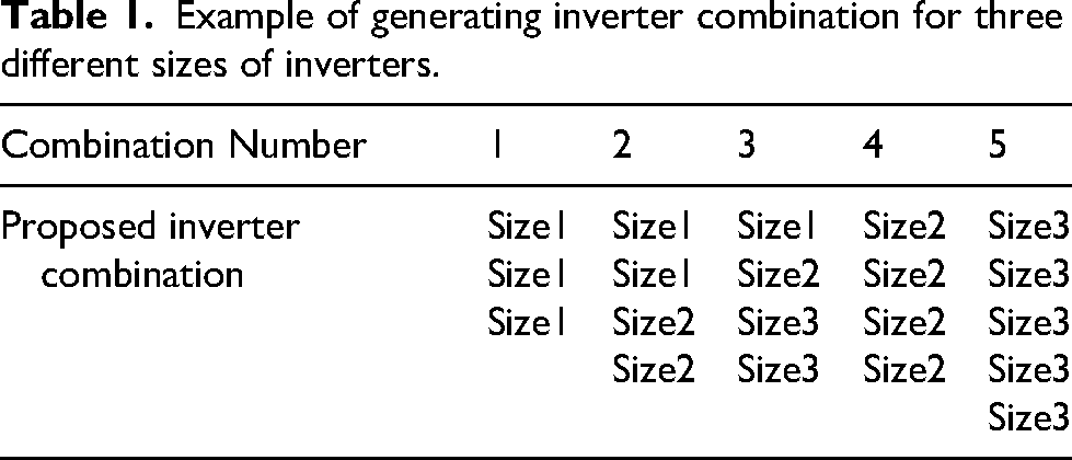
In this research, a minimum number of three inverters size is considered. The three different inverters choices are named Size1, Size2, and Size3, where (Size1 > Size2 > Size3). A sample of inverters’ combinations is illustrated in Table 1.
Example of generating inverter combination for three different sizes of inverters.
PV panels’ layout generation
In this research, each distinct combination of inverters is treated as a separate case and thoroughly examined on an individual basis. This process starts by distributing the PV panels among tables and assigning each table specific coordinates. Subsequently, the necessary quantity of PV panels is accurately calculated, followed by their meticulous distribution across the designated tables. To facilitate subsequent calculations and analyses, the specific data about each inverter is stored together with its corresponding group of tables.
Once generating the layout of PV panels is, every inverter is assumed to occupy one table based on the initial assumption that the land continues and has no vertical displacements. The width of the table is calculated by multiplying the number of PV panels assigned to each inverter by the PV panel width divided by the number of PV panel rows in each table. Depending on virtual coordinates, the first table is assigned to ([1,1], [table width, 1], [1, table length], [table width, table length]). If the table width is shorter than the land width, otherwise, the table will continue on the second row, and the procedure continues until all tables to virtual coordinates.
Calculating and optimizing cable length for different inverter locations
DC cables length calculation methodology
Figure 3 shows the proposed methodology for calculating the required DC cable length. The length of the required DC cable running from the DC output node to any inverter location is given in (2), where all inverter locations and DC outputs are given as coordinate pairs (x, y).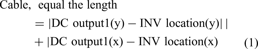
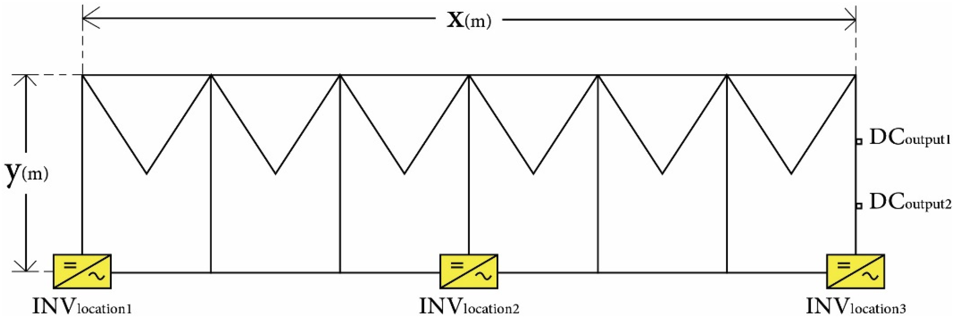
Calculating DC cable length.
AC cables length calculation methodology
In this part, Dijkstra's shortest path algorithm is used to determine the best route for the AC cables from the inverter to the connection room. The task of identifying the shortest path is a well-known problem, and Dijkstra's algorithm serves as a common solution for this purpose. Dijkstra algorithm is illustrated in Figure 4. The Dijkstra algorithm is a method for determining the shortest routes between nodes in a weighted graph, which could, for instance, be a network of connections for electrical cables (Farhan, 2019; Hassaine et al., 2014; Wei et al., 2019).

Flowchart for parallel Dijkstra algorithm (Hassaine et al., 2014).
When applying Dijkstra's shortest path algorithm to the photovoltaic project, the inverter is considered as the source node (v1), and the connection room as the end node (v2). The shortest path from v1 to v2 is to be determined. Then as usually implemented in PV projects, cables run in horizontal and vertical trenches.
Selecting the optimum inverter location
In this research, the optimal location of inverters is achieved when having the minimum required DC cables, and minimum required AC cables, or when compromising the two parameters. In general, the cost and the length of DC cables are much more than the AC cables (Good and Johnson, 2016; Korkas et al., 2015, 2018). Thus, the weight of the DC cable length factor is more dominant in this optimization process. However, it is also good to consider the minimum length of AC cables as AC cable length affect critically the voltage level at the electricity grid integration point to consider these two factors, two approaches are adopted in this research as follows,
In the case, the inverter location is chosen based on the length of connecting DC cables to every possible inverter location. Inverters are usually located near the bottom of PV-tables. Therefore, three locations are tested in each table (bottom-left, bottom-middle, and bottom-right) (see Figures 5(a) and 5(b)). Finally, the locations are compared based on the required DC cables length. Here once the optimum location is determined, the length of ac cables is located from the chosen coordinate regardless of its length.

Connecting dc lines to inverter location 2. Connecting dc lines to inverter location 4.
In Figures 4(a) and 4(b), the methodology employed to minimize the utilization of DC cables is illustrated. In Figure 4(a), the diagram represents the necessary DC cables when positioning one inverter on the bottom-middle side of the first table. Conversely, Figure 4.b depicts the required DC cables for the same inverter when located on the bottom-left side of the second table. This process is applied to all potential locations of each inverter, and the optimal placement is determined by considering the shortest length of the DC cables.
In this case the inverter location is chosen based on the length of connecting AC-cables from every possible location to the connection room. Finally, the locations are compared based minimum ac cables length. Once the optimum location is determined, the length of DC cables is located from this coordinate regardless of its length (See Figures 6(a) and 6(b)).

Connecting inverter location 1 to the connection room. Connecting inverter location 5 to the connection room.
Figures 5(a) and 5(b) demonstrate a comparison between the necessary AC cables when positioning the inverter at two different locations; either at the bottom-left of the first table or at the bottom-middle of the second table. This method involves testing all potential locations for each inverter, as mentioned earlier, and selecting the optimal placement based on the shortest AC cables.
After selecting the best location of each inverter, the earthing cables lengths are calculated. The earthing cable can be connected to any point on the table; therefore, the point with the minimal cable length is chosen for earthing connections.
Finally, results are extracted for the two approaches for minimal AC cables or minimal DC cables. Here, it's clearly noticed that the DC cables contribute to more than 75% of the total cable's length in the project. Thus, the approach of minimizing the DC cables at the expense of AC cables is preferable. Eventually, the output of this process are Ac cables lengths, dc cables lengths, and earthing cables lengths are the main outputs.
Results and discussion
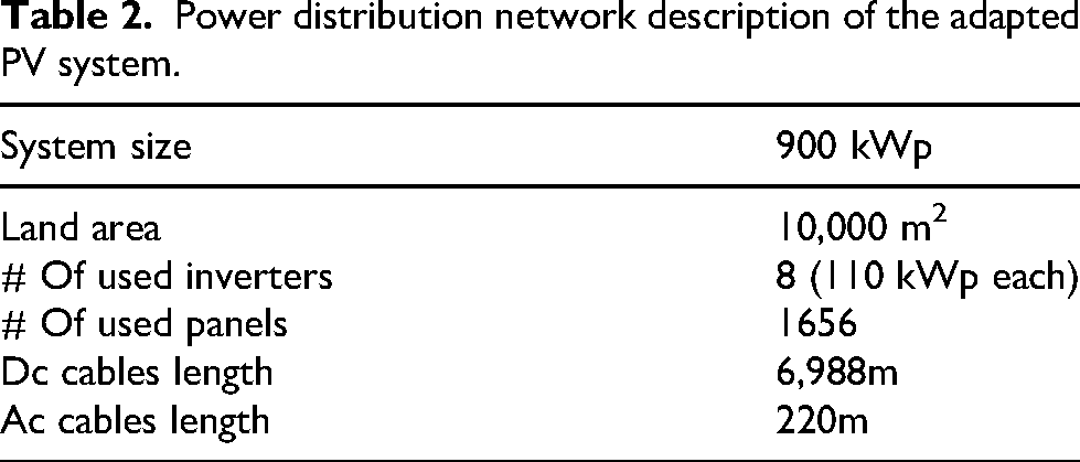
In this research, the results of the proposed method are validated by an actual PV system with a capacity of 900 kWp. The system is located in Hebron city, Palestine and it occupies a 10,000.0 m2 land as shown in Figure 7. Table 2 shows a description of the AC and DC network of the system according to system's operator.

Project's land contour (case study).
Power distribution network description of the adapted PV system.
The results of the proposed method in this paper is compared to the results of the intuitive and conventional approach that is used in designing the aforementioned system in terms of cable configurations (DC, AC and earthing cables) and the placement methodology of PV inverters.
For comparison purposes, the same PV panel's type is used in this research. Meanwhile, three different inverters are considered (the actual system contains one inverter type which is Option 3. Tables 3 and 4 show the specification of the adapted PV panels and inverters
Specification of the adapted PV panel.

Specification of the adapted inverters.

Based on the conventional method applied to the depicted land in Figure 3, the inverter's location was chosen based on engineering sense. The designer chose a location that appeared to offer shorter cable lengths. This process was subsequently utilized when connecting the cables. The obtained outcomes are shown in the Table 5 below,
Characteristics of the power distribution network of the actual PV system.

On the other hand, the proposed method is used to design the power distribution network considering the data of the adapted system. Initially, the land area is rectified to a rectangular shape measuring 50 by 182 meters (910 m2). After that, eleven possible scenarios are generated based on the proposed methodology considering same parameters of the adapted system by three inverters type instead of one. Table 6 shows the obtained results by the proposed method
Optimization results.

From Table 6, in the first combination (combination #0), where five inverters of 110 kW size with one 80 kW inverter are used, a significantly low cables length is recorded, whether on the first or the second approach. In this case, the total cable length of the first combination is 5558 m for the first approach and 8450 m for the second.
On the other hand, a gradual increase in the total cable length is noticed when increasing the number of used inverters and decreasing the size. This can be seen clearly in Combination#1 which recorded 5451 m for the first approach and 8173 m for the second approach. Meanwhile, combination #2 recorded 5898 m for the first approach and 9117 m for the second. Moreover, by looking into the final combination (combination #10), the total cable length values jump to 7111 m for the first approach and 10,682 m for the second.
This is to say that Scenario #1 is considered the best choice as it achieves the minimum length of cables. This achieves a 26.9% reduction in required cables’ length as compared to the conventional methodology of designing method which resulted in a total cable length of 7208 m.
After all, there are some minor errors in the proposed method due some factors. These factors are; first the proposed method assumes that the land is continuous and flat, whereas the actual case study involves land with varying vertical displacements. This discrepancy between the assumption and reality introduces inaccuracies in the calculations. Additionally, the proposed method approximates the land as a perfectly drawn rectangle, which is not typically representative of real PV projects. Consequently, this approximation process, which occurs during the pre-processing stage, leads to an accumulation of approximately 5% error in the cable length results. Moreover, due to the vertical displacements in the land, only 1656 panels could fit on the site, as more space was required between the tables. This is in contrast to the proposed theoretical analysis, which assumed a lower requirement for spacing between tables, allowing for more flexibility in distributing the PV panels.
Moreover, to validate the rectangular land approximation and orthogonal trench routing, a layout of a 1.5 MWp PV system is utilized (720 Wp PV panel). The land of this layout does not have a rectangular shape. Thus, to validate the assumption of the proposed method, the electrical grid is first established manually and then the length of the cables are estimated. After that, the proposed method is used to calculate the required length of the cables. Figure 8 shows the utilized layout and the generated DC grid by the proposed method. Meanwhile, Table 7 shows a comparison between the quantities calculated by the system and the quantities estimated by hand.

A layout of a 1.5 MWp PV system generated by the proposed method.
Addtional validation for cable length for a non rectangluar land.

The results from the table shows that the proposed method is still able to generate a layout of electrical cable with less length as compared to the conventional method even when the land is not perfectly rectangular. However, in this case the method is found relativity less efficient.
Conclusion
This paper proposed an optimum methodology for designing layout of the power distribution network for grid connected PV power plant considering solar inverter size and location, as well as cable's size and configuration. This was achieved by an iterative method by using Python code to propose various inverter combinations and test different inverter locations. This method offered the shortest cables length and the optimum inverter locations. Both the conventional and the proposed methodology were applied on a 900-kWP grid-connected PV system for comparison purposes. Ten different inverter combinations were suggested and analyzed using the proposed method, which offers the choice of minimizing DC cables at the expense of AC cables of vice versa. Results showed that the DC cables account to more than 75% of the total cables length which supports the first approach of minimizing DC cables length. Results also showed that when the number of used inverters increases with lower size, a gradual increase in the total cable length is noticed. Moreover, a comparison of the best-case scenario was conducted. The results of this comparison showed that the proposed methodology demonstrates a 26.9% decrease in total cable length. In conclusion, the proposed methodology offers the potential to enhance the selection of inverter parameters, resulting in a more efficient and optimized PV project with reduced cable lengths.
Footnotes
Acknowledgment
The authors would like to thank Eng. Sura Malhis from Palestine Telecom Corporation for her extreme help in adjusting the data analysis methods. Authors would like to extend their thanks to Eng. Zaina Ruzzeh from An-Najah Company for Consultancy and Technical Studies for providing the real data of the actual PV system used in the comparison.
Ethical approval
The research does not include any type of experiment on humans or animals.
Funding
The authors received no financial support for the research, authorship, and/or publication of this article.
Declaration of conflicting interests
The authors declared no potential conflicts of interest with respect to the research, authorship, and/or publication of this article.
Data availability statement
Data are available upon request.