
Abstract
This study explores the mechanical, water absorption, and erosive wear properties of hybrid polymer composites reinforced with treated hemp, carbon, and basalt fibers. The composites were fabricated using the hand lay-up method, with epoxy resin as the matrix and fillers (CaCO3 and coconut fiber) incorporated to enhance performance. Treated hemp fibers underwent 5% NaOH treatment to improve fiber-matrix adhesion, and ASTM standards were followed for tensile, flexural, and impact tests. Water absorption was monitored over 10 days, and solid particle erosion was assessed under varying impingement angles. Results showed that Sample B2 (20% treated hemp, 6% basalt) exhibited superior mechanical properties, including flexural strength (15% higher than comparable samples) and impact resistance (10% higher). Treated fibers and fillers minimized water absorption, while erosion resistance was maximized in carbon-basalt composites. SEM analysis confirmed uniform fiber dispersion and strong interfacial bonding in optimal samples, leading to improved load transfer and mechanical stability. This study demonstrates the potential of hybrid composites as high-performance materials for automotive, aerospace, and construction applications, emphasizing the critical role of balanced fiber composition and chemical treatments in optimizing material properties.
Introduction
Composite materials have increasingly become integral to various engineering applications due to their superior mechanical properties, lightweight nature, and versatility. The incorporation of natural fibers into polymer matrices has garnered significant attention in recent years as a sustainable alternative to synthetic fibers, driven by environmental concerns and the need for eco-friendly materials. Natural fibers like hemp are biodegradable, cost-effective, lightweight, and exhibit high specific strength, reducing environmental impacts compared to synthetic fibers. Natural fibers such as hemp offer advantages including biodegradability, low density, and high specific properties, making them suitable for composite reinforcement. 1 Natural fiber-reinforced composites (NFRCs) have been extensively studied for their potential applications in automotive, aerospace, and construction industries. Hemp fibers, in particular, have shown promise due to their high tensile strength and modulus, as well as their availability and renewability. 2 However, the hydrophilic nature of natural fibers poses challenges, such as poor adhesion to hydrophobic polymer matrices, which can lead to suboptimal mechanical properties. Alkali treatment (NaOH) of hemp fibers has been demonstrated to improve fiber-matrix adhesion by removing surface impurities and increasing surface roughness.3,4
Hybrid composites, which combine natural fibers with synthetic fibers such as carbon and basalt, have emerged as a strategy to enhance the overall performance of composites. These hybrid systems can leverage the high strength and stiffness of synthetic fibers while benefiting from the sustainability and cost-effectiveness of natural fibers. 5 Combining different fibers can also mitigate the drawbacks associated with each fiber type, resulting in composites with tailored properties for specific applications. 6 To enhance the interfacial bonding between natural fibers and polymer matrices, chemical treatments are commonly employed. Alkaline treatment (NaOH) is one of the most effective methods for improving fiber-matrix adhesion by removing surface impurities and increasing surface roughness. 3 Studies have shown that NaOH treatment can significantly enhance the mechanical properties of hemp fiber composites by improving wettability and reducing the fiber’s hydrophilicity. 7 The mechanical properties of hybrid composites are crucial for their potential applications in various industries. Natural fibers, such as hemp, can be effectively combined with synthetic fibers like carbon and basalt to produce composites with enhanced mechanical performance. Hemp fibers are known for their high tensile strength and modulus, which make them ideal for reinforcing polymer matrices. However, their hydrophilic nature often results in poor adhesion with hydrophobic matrices, leading to suboptimal mechanical properties. 8 To improve the interfacial bonding between natural fibers and polymer matrices, chemical treatments such as alkali treatment (NaOH) are commonly employed. Alkaline treatment helps remove impurities like lignin and wax from the fiber surface, increasing surface roughness and enhancing fiber-matrix adhesion. 2 Studies have shown that NaOH treatment can significantly enhance the mechanical properties of hemp fiber composites. For instance, Kabir et al. reported that NaOH-treated hemp fibers exhibited improved tensile strength and modulus compared to untreated fibers. 3
Hybrid composites, which combine natural fibers with synthetic fibers, offer a promising approach to achieving superior mechanical properties. The integration of fibers such as carbon and basalt with hemp fibers results in composites with high strength, stiffness, and toughness. Carbon fibers provide high tensile strength and modulus, while basalt fibers offer good thermal stability and resistance to environmental degradation. By combining these fibers in a hybrid composite,9,10 it is possible to achieve a balance of mechanical properties that surpasses those of single-fiber composites. 11 Several recent studies have investigated the mechanical properties of hybrid composites. For example, Khan et al. reviewed the mechanical properties of hybrid composites reinforced with natural and synthetic fibers. They found that hybrid composites exhibited improved tensile and flexural properties compared to single-fiber composites. The authors attributed this improvement to the synergistic effects of combining different types of fibers, which enhanced the overall performance of the composites. 12 Similarly, Zhou et al. reported that hybrid composites reinforced with natural and synthetic fibers exhibited better mechanical properties compared to composites reinforced with only natural fibers. 13
Erosion resistance is a critical property for composites used in abrasive environments. The erosion behavior of hybrid composites is influenced by factors such as fiber type, matrix composition, and processing conditions. The ASTM G76 standard provides guidelines for conducting erosion tests using solid particle impingement. 14 Erosion testing is typically performed using an air jet erosion testing machine, where erodent particles are accelerated by compressed air and directed at the composite surface at a specific impingement angle. Recent studies have shown that hybrid composites exhibit improved erosion resistance compared to single-fiber composites. The synergistic effects of combining different fibers can enhance the composite’s resistance to erosion by distributing the impact energy more effectively across the fibers. For example, Mahapatra et al. investigated the erosion behavior of epoxy/polyester hybrid composites reinforced with glass and jute fibers. They found that the hybrid composites exhibited lower erosion rates compared to composites reinforced with only glass or jute fibers. The authors attributed this improvement to the enhanced interfacial bonding between the fibers and the matrix, which distributed the impact energy more effectively. 15 The erosion resistance of hybrid composites can be further improved by optimizing the fiber-matrix interface through chemical treatments. For instance, Mahesh studied the erosion behavior of jute fabric composites treated with NaOH. He reported that the treated composites exhibited lower erosion rates compared to untreated composites, which was attributed to the improved interfacial bonding between the fibers and the matrix. 16
Water absorption is a significant concern for composites exposed to humid or aquatic environments. The hydrophilic nature of natural fibers can lead to high water absorption, resulting in swelling, plasticization, and degradation of the polymer matrix, which adversely affects the mechanical properties of the composite. 17 Studies have shown that hybrid composites can exhibit varied water absorption behaviors depending on the type and treatment of fibers used. For instance, Sreekumar et al. investigated the water absorption behavior of sisal/polyester composites and found that water absorption decreased with the incorporation of glass fibers. The authors attributed this to the lower water absorption of glass fibers compared to sisal fibers, which reduced the overall water absorption of the composite. 18 Similarly, Bahrami et al. reported that hybrid composites reinforced with natural and synthetic fibers exhibited lower water absorption compared to composites reinforced with only natural fibers. 19 The water absorption behavior of hybrid composites can be further improved by chemical treatments that reduce the hydrophilicity of natural fibers. For example, Mohammed et al. studied the water absorption behavior of NaOH-treated hemp fiber composites and reported a significant reduction in water absorption compared to untreated composites. The authors attributed this to the removal of hydrophilic components from the fiber surface and the improved fiber-matrix adhesion. 20
The primary objective of this study is to develop and characterize hybrid fiber composites reinforced with hemp, carbon, and basalt fibers. Specifically, the study aims to investigate the effects of surface treatment on hemp fibers and its impact on fiber-matrix adhesion and composite properties, evaluate the erosion resistance of these composites under different conditions, assess water absorption behavior and its influence on mechanical properties, determine tensile, flexural, and impact properties in accordance with ASTM standards, and analyze microstructural characteristics using Scanning Electron Microscopy (SEM) to understand the relationship between material structure and mechanical performance.
Materials and methodology
Materials
Erosion test parameters.

Composite preparation
All purchased and derived raw materials were brought to the fabrication site. The preparation process involved several steps to ensure the proper creation of the polymer composites. First, the mold materials were brushed with a releasing agent, such as wax, and covered with a plastic transparent sheet to facilitate easy removal of the final composite. Next, the matrix preparation commenced. Epoxy resin and hardener were mixed in a predetermined ratio of 10:1. This mixture was continuously mechanically stirred to ensure proper blending. After achieving a homogeneous mixture, the filler material (5 wt%) was added. The mechanical stirring continued until the filler was uniformly distributed throughout the mixture. Care was taken to stop the stirring process as soon as heat generation was observed, indicating the onset of the exothermic curing reaction.
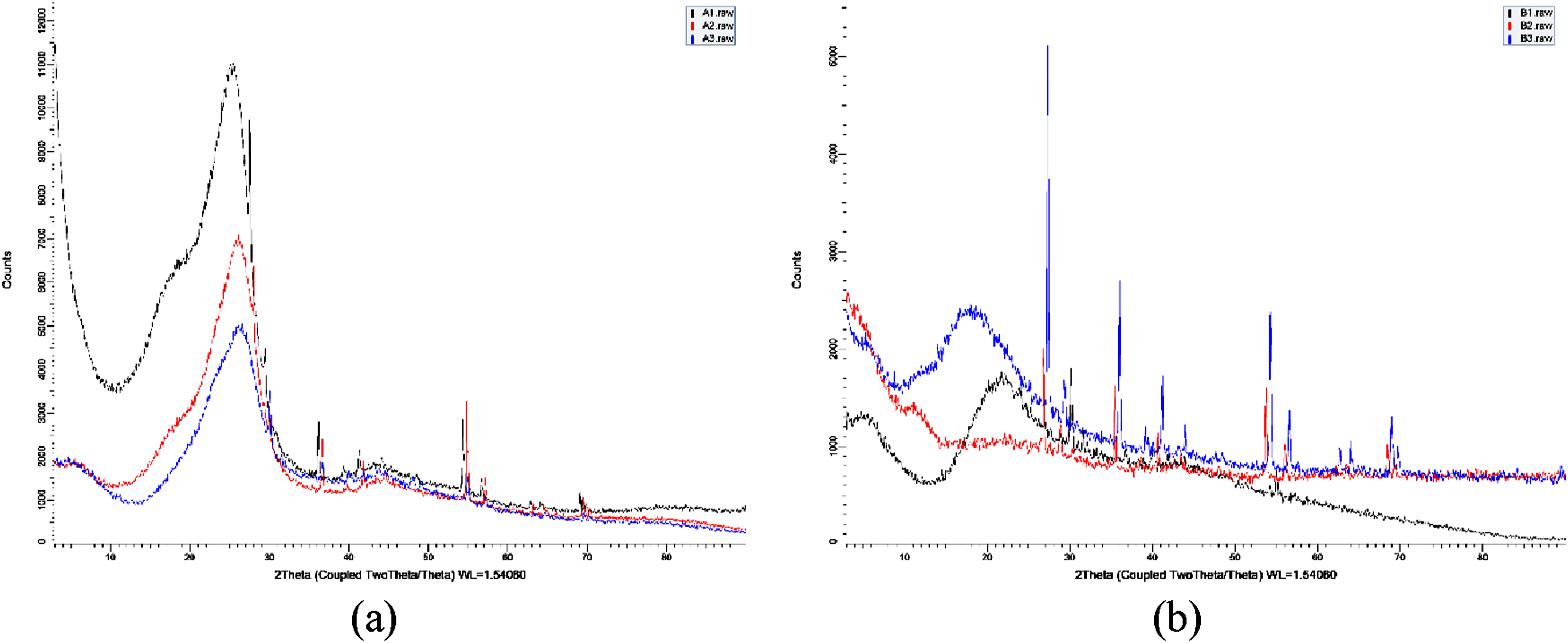
Following the matrix preparation, the composites were fabricated using the hand lay-up method. First, the bottom mold layer was prepared by placing the first layer of carbon or basalt fiber. The mixed epoxy was then poured onto this layer to ensure proper bonding. The layer arrangement for the proposed work consisted of alternating layers of carbon or basalt fiber and hemp fiber in the sequence: carbon/basalt fiber – hemp fiber – carbon/basalt fiber – hemp fiber – carbon/basalt fiber (Figure 1). Epoxy was applied between each layer to facilitate bonding. The orientation of the hemp fibers was maintained at 90°, while the carbon and basalt fibers were oriented at 0°/90°. This process ensured a strong interfacial bond between the layers, resulting in a cohesive composite structure. After completing the layering process, the mold setup was placed into a compression machine to apply a load of 45 psi, which helped the matrix spread evenly throughout the composite. During this process, any excess material was expelled, ensuring uniform distribution and proper compaction of the composite layers. Uniform layer distribution is achieved by alternately stacking fibers with matrix resin and applying pressure during curing. Following the compression, the composite was allowed to cure for 6 to 7 h, resulting in a robust and well-bonded final product. The materials were combined in various proportions to prepare the polymer composites, as outlined in Figure 2. The compositions were designed to explore the effects of different fiber contents and types on the mechanical properties of the composites. The preparation of these composite materials aimed to evaluate the mechanical properties based on the varying fiber content and types. Each sample was analyzed to determine the optimal combination for enhanced performance. The XRD pattern of prepared composite materials is shown in Figure 3. Proposed fiber layer arrangement. Proposed various samples raw material combination. XRD image of (a) carbon fiber hybrid composite and (b) basalt fiber hybrid composite.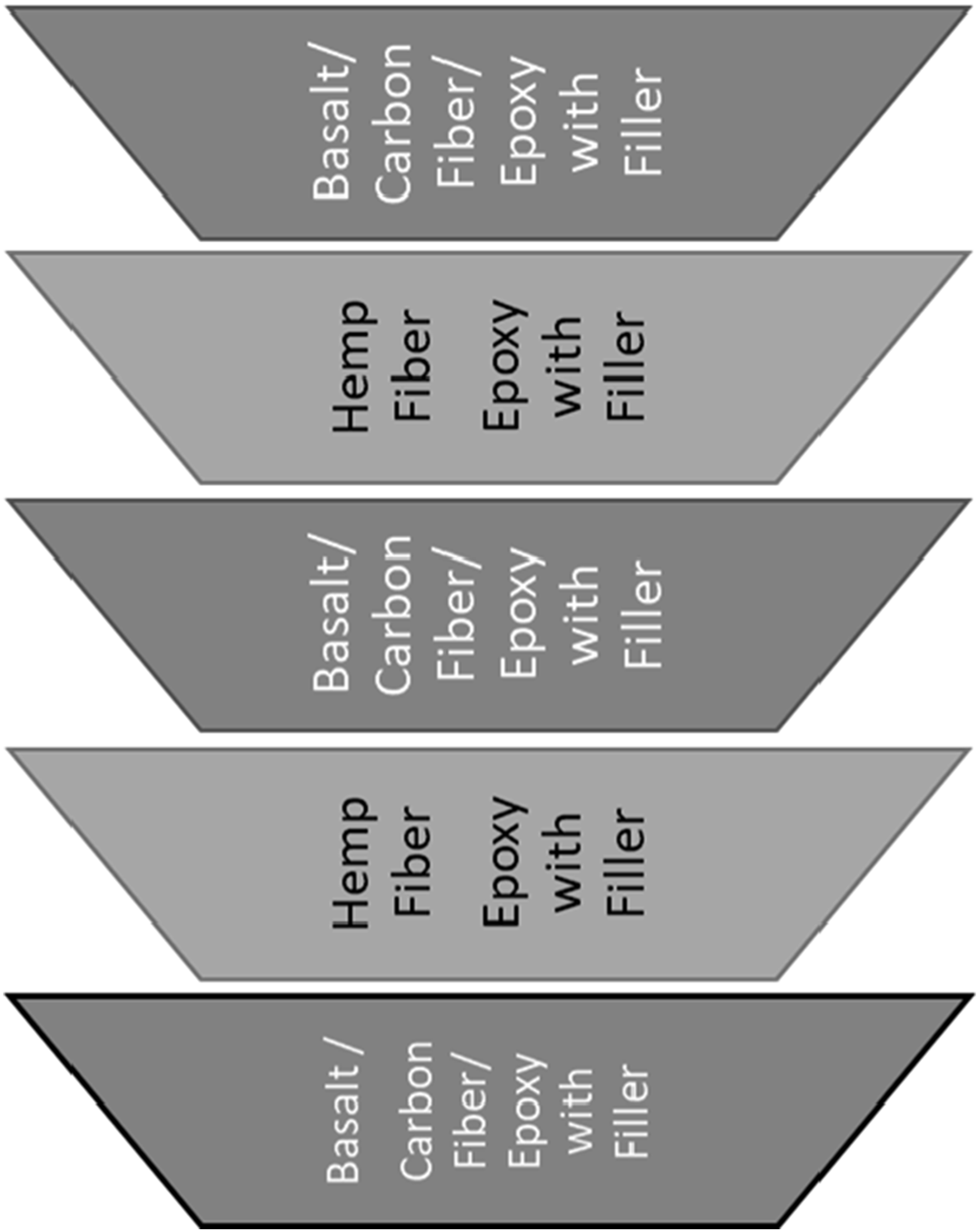

Mechanical properties analysis of the prepared composite
After the composite fabrication, the prepared composite underwent mechanical property analysis, including tensile, flexural, and impact testing, conducted in accordance with ASTM standards. Three samples were evaluated for each test, and the mean values were recorded. Tensile specimens were prepared as per ASTM D3039 (Figure 4(a)) and tested using an FIE Make, UTES-100, Universal Testing Machine with a maximum load capacity of 100 kN, a minimum test speed of 0.1 mm/min, and a maximum test speed of 300 mm/min. The specimens were fixed between grips and subjected to a crosshead speed of 0.3 mm/min until fracture occurred. Three samples of each configuration were tested to ensure reliable results. For the flexural test, specimens were prepared according to ASTM D790 (Figure 4(b)) and subjected to a three-point bending load with a crosshead speed of 1 mm/min. A constant span length was maintained for the flexural specimens as per ASTM std, with three samples of each configuration tested to obtain accurate measurements. The impact strength was assessed using the Charpy impact test, following ASTM D256 (Figure 4(c)), and performed on the AIT 300 EN Pendulum Impact Testing Machine with a hammer energy of 15 J. Three samples of each configuration were tested, and the absorbed impact energy (J) was recorded. These mechanical property analyses provided essential data on the composite’s performance under various loading conditions, thoroughly evaluating its structural integrity and potential applications. (a) Tensile specimens as per ASTM 3039. (b) Flexural specimen as per ASTM 790. (c) Impact specimen as per ASTM D 256.
Water absorption analysis
The present study investigated water absorption following ASTM D570 guidelines. Hybrid fiber composite specimens were immersed in distilled water at room temperature for 10 days. At regular intervals, the samples were removed, gently cleaned with a soft tissue to remove surface water, and weighed using a precision balance (up to 200 g). The samples were then re-immersed to continue absorption, with mass measurements taken and recorded at each interval. Weighing was completed within 30 s to minimize evaporation errors. The percentage of water absorption (wt (%)) was calculated using the appropriate equation.
21

Erosion study
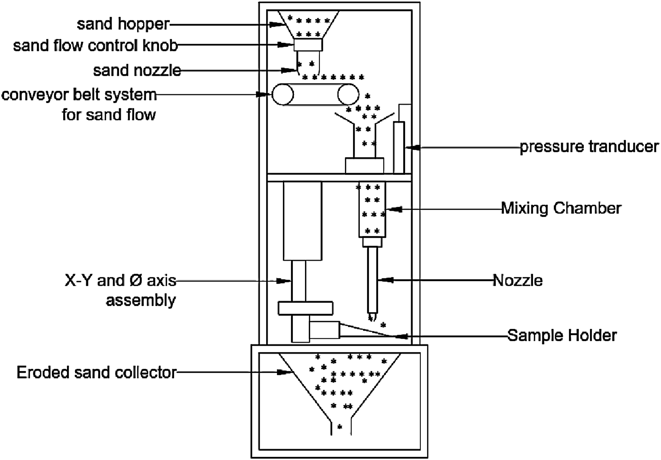
In the current study, an air jet erosion testing machine (TR-470, Ducom, Bangalore, India) was used to assess the erosion behavior of specimens per ASTM G76 standards. Erodent particles were combined with compressed dry air and directed at the sample on an angled holder. Test parameters (Table 1) such as particle velocity, erodent feed rate, and testing time were kept constant, while the impingement angle varied. The study used 50 µm alumina oxide particles, and the erosion test was conducted at room temperature. Samples measured 10 × 10 × 4 mm3 and were tested at angles of 30°, 45°, and 90°. Before and after testing, samples were cleaned, dried, and weighed to calculate erosion rates using equation (2). The erosion morphology was analyzed using SEM. The schematic view of air jet erosion machine is shown in Figure 5. Schematic diagram of erosion test.
Wfinal = weight of the sample after erosion test in g.
Ef = erodent flow rate in/sec.
t = discharge time of erodent in sec.
Micrography analysis
Utilizing a Scanning Electron Microscope (SEM) (Make: Zeiss FE-SEM, Germany), the researcher examined the fiber-matrix interface of the composite laminates. The specimens’ conductivity was enhanced by applying a gold coating before capturing the micrographs. This coating ensured clear visibility of the sample surface and improved the conductivity of the non-conductive polymer specimens. SEM imaging was crucial for a thorough examination of the surface characteristics and bonding at the composite material’s fiber/matrix interface. This technique provided valuable insights into the mechanical properties and overall performance of the composite. It was particularly useful for analyzing fracture surfaces after mechanical testing, observing microstructural changes due to water absorption, and assessing erosion behavior and bonding. The treated hemp fiber is shown in Figure 6. SEM identifies fiber-matrix adhesion and microstructural changes, correlating these observations with mechanical performance. Treated hemp fiber SEM view.
Results and discussion
Mechanical property studies
The Figure 7(a) compares the tensile strength of nine composite material samples of three groups (A, B, and C) based on their fiber composition. The tensile strength increases by approximately 15% from A1 to A2 and decreases by about 10% from A2 to A3. Material group B shows a similar pattern with a 12% increase from B1 to B2 and a 15% decrease from B2 to B3. In Group C, the strength increases by around 13% from C1 to C2 and decreases by 8% from C2 to C3. Comparing the highest tensile strength samples from each group, A2 exhibits 14% higher strength than B2 and 18% higher than C2, while B2 shows a 3% higher strength than C2. The optimal strength in A2 suggests that a composition of 20% treated hemp fiber and 6% carbon fiber maximizes performance, emphasizing the importance of balanced fiber content. The observed trends indicate that beyond a critical fiber content, tensile strength diminishes due to fiber agglomeration disrupting matrix continuity. These findings align with studies indicating that optimal fiber-matrix ratios enhance mechanical performance, while excessive fiber content leads to stress concentrations and reduced strength.22,23 Mechanical properties of composites (a) tensile strength, (b) flexural stress, and (c) impact strength.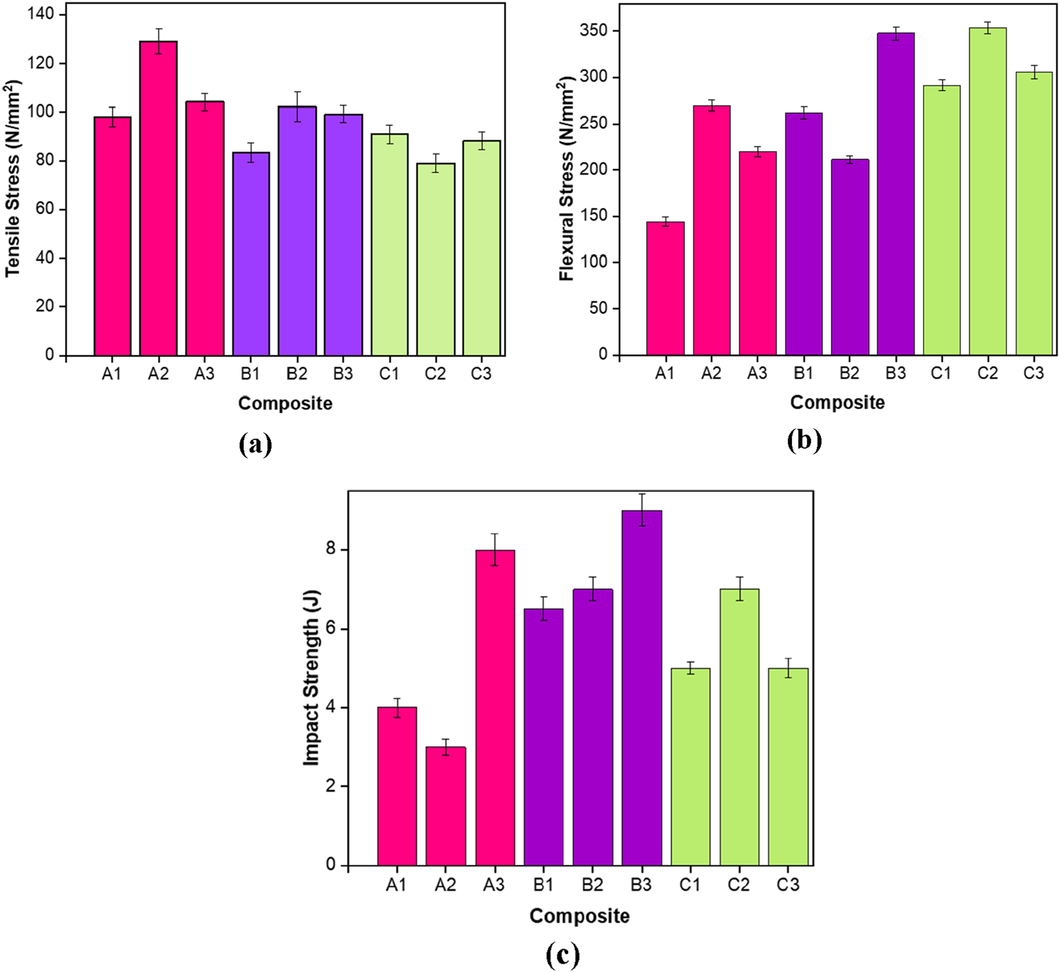
The Figure 7(b) compares the flexural strength of the composite samples, Within Group A, flexural strength increases by approximately 25% from A1 to A2 and decreases by about 5% from A2 to A3. Group B shows a 15% increase from B1 to B2 and a 5% decrease from B2 to B3. In Group C, the strength increases by around 5% from C1 to C2 and decreases by 3% from C2 to C3. Comparing the highest flexural strength samples from each group, B2 exhibits 2% higher strength than C3 and 25% higher than A3, while C3 shows a 20% higher strength than A3. The optimal strength observed in B2 suggests that a composition of 20% treated hemp fiber and 6% basalt fiber maximizes flexural performance, making B2 the best specimen. This emphasizes the importance of balanced fiber content. The observed trends indicate that beyond a critical fiber content, flexural strength diminishes due to fiber agglomeration disrupting matrix continuity. These findings align with studies indicating that optimal fiber-matrix ratios enhance mechanical performance, while excessive fiber content leads to stress concentrations and reduced strength.24,25
The Figure 7(c) analyze the impact strength variations of composite samples, Within Group A, impact strength increases by approximately 35% from A1 to A2 and remains almost the same from A2 to A3. Group B shows a 30% increase from B1 to B2 and a 10% decrease from B2 to B3. In Group C, the strength increases by around 10% from C1 to C2 and remains almost constant from C2 to C3. Comparing the highest impact strength samples from each group, B2 exhibits 10% higher strength than C3 and 35% higher than A3, while C3 shows a 25% higher strength than A3. The optimal impact strength observed in B2 suggests that a composition of 20% treated hemp fiber and 6% basalt fiber maximizes impact performance, making B2 the best specimen. Fiber agglomeration at higher content (B3) reduces strength, while balanced fiber dispersion (B2) maximizes impact strength. B2’s treated hemp and basalt fibers, combined with optimal matrix interaction, enhance toughness and impact energy absorption. The observed trends indicate that beyond a critical fiber content, impact strength diminishes due to fiber agglomeration disrupting matrix continuity. 26 The study evaluated the tensile, flexural, and impact strengths of nine composite material samples, each incorporating different combinations of treated hemp fiber, carbon fiber, basalt fiber, and consistent fillers (2.5% CaCO3 and 2.5% coconut fiber). The findings highlight the significant role of fillers in enhancing mechanical properties. Sample B2, with 20% treated hemp fiber and 6% basalt fiber, and demonstrated the best overall performance across all properties. The addition of CaCO3 and coconut fiber fillers contributed significantly by improving stiffness, toughness, and energy absorption. Fillers improve mechanical properties by enhancing interfacial bonding and distributing stress uniformly across the matrix and also the even fiber alignment and strong adhesion resist deformation, maximizing impact strength in composites. CaCO3 acted as a stiffening agent and enhanced toughness by distributing stress uniformly and preventing stress concentrations.27,28 Coconut fiber improved reinforcement and energy absorption, crucial for resisting impact forces without fracturing.29,30 The consistent use of these fillers provided a baseline improvement in mechanical properties by ensuring better stress distribution and enhancing the fiber-matrix interface, aligning with existing literature on the importance of optimal filler use in composite materials. Combining natural and synthetic fibers optimizes tensile, flexural, and impact properties through balanced strength and energy absorption.
Uniform dispersion minimizes stress concentrations and enables efficient load transfer, improving mechanical properties. The SEM images (Figure 8) of material set A reveal a well-dispersed and tightly bonded fiber structure within the matrix. In the first image at ×3284 magnification, the particles appear uniformly distributed with minimal agglomeration, indicating effective load transfer between fibers and the matrix. The second image at ×1251 magnification shows an interwoven arrangement of fibers, including treated hemp and carbon fibers, which are well-embedded in the matrix. This suggests strong fiber-matrix adhesion, contributing to the composite’s enhanced mechanical properties. The optimal fiber content observed in these images corresponds to the highest mechanical performance, supporting the importance of balanced fiber dispersion in achieving superior tensile, flexural, and impact strengths. The SEM images of material set B exhibit a well-distributed fiber structure within the matrix, especially in the optimal sample. At higher magnifications, the fibers, including treated hemp and basalt fibers, are seen to be evenly dispersed with minimal agglomeration, which is crucial for effective load transfer and enhanced mechanical properties. The images reveal strong fiber-matrix adhesion, with fibers well-embedded in the matrix, contributing to increase tensile, flexural, and impact strengths. The uniform distribution and strong bonding observed in the optimal sample (B2) explain its superior mechanical performance, emphasizing the significance of a balanced fiber content in preventing agglomeration and maintaining matrix continuity. The SEM images of material set C display a well-integrated fiber structure within the matrix, particularly in the optimal sample. The fibers, including treated hemp and carbon fibers, appear to be uniformly distributed and well-embedded, indicating strong fiber-matrix adhesion. This uniformity is critical for effective load transfer and mechanical performance. The images show minimal fiber agglomeration, which aligns with the enhanced tensile, flexural, and impact strengths observed in the optimal sample (C2). The effective dispersion and strong bonding of fibers highlight the importance of maintaining an optimal fiber content to achieve superior mechanical properties and prevent disruptions in matrix continuity. Fracture analysis for mechanical properties through SEM. (a) Fracture in tensile specimen. (b) Fiber pull out in tensile specimen. (c) Fiber-matrix adhesion. (d) Fillers evenly spread in flexural specimen. (e) Fracture in impact specimen. (f) Fiber pull out in impact specimen.
Water absorption test
The moisture absorption data for material set A (Figure 9(a)), which includes treated (NaOH) hemp fiber, carbon fiber, and fillers (CaCO3 and coconut), indicates a clear pattern of moisture uptake. The samples demonstrate an initial rapid absorption phase, followed by a stabilization period as they reach saturation. The optimal sample, A2 (20% treated hemp fiber and 6% carbon fiber), absorbs moisture at a slower rate compared to A1 and A3. The presence of fillers, CaCO3 and coconut, contributes to reducing water uptake by filling micro-voids and enhancing the matrix’s impermeability. The strong interfacial bonding between the fibers and matrix, as observed in SEM images, minimizes the pathways for water ingress. Studies suggest that the use of CaCO3 as a filler improves moisture resistance and mechanical properties by providing better dispersion and reducing matrix porosity.22,24 The effective load transfer and reduced voids in A2 enhance its durability and resistance to environmental degradation. The moisture absorption data for material set B (Figure 9(b)), which includes treated hemp fiber, basalt fiber, and fillers (CaCO3 and coconut), shows a similar absorption trend. The samples initially absorb moisture rapidly, followed by a gradual leveling off. The optimal sample, B2 (20% treated hemp fiber and 6% basalt fiber), absorbs moisture more slowly compared to B1 and B3. The use of basalt fiber, known for its moisture resistance, along with the fillers, enhances the composite’s overall impermeability. SEM images reveal strong fiber-matrix adhesion and fewer voids in B2, contributing to its lower moisture absorption rate. Treated fibers and fillers reduce voids and hydrophilicity, enhancing water resistance and preventing property degradation.
31
Research indicates that the inclusion of basalt fibers and fillers like CaCO3 can significantly reduce water absorption and improve mechanical performance by enhancing the composite’s barrier properties23,25 For material set C (Figure 9(c)), which consists of treated hemp fiber, carbon fiber, and fillers (CaCO3 and coconut), the moisture absorption data reveals consistent trends with other sets. The samples exhibit an initial rapid uptake of moisture, followed by a plateau. Water absorption causes swelling and matrix degradation, minimized by fillers (e.g., CaCO3) and chemical treatments that reduce fiber hydrophilicity. The optimal sample, C2 (20% treated hemp fiber and 2% carbon fiber), demonstrates the least moisture absorption among the C samples. The presence of carbon fiber, known for its hydrophobic nature, along with the fillers, minimizes moisture pathways. B2’s lower absorption is due to basalt fiber’s hydrophobicity and uniform filler distribution reducing voids.
32
From the Figure 10, the SEM images show strong fiber-matrix bonding and uniform fiber distribution, reducing void formation. Studies have shown that carbon fibers, combined with fillers, effectively enhance the composite’s resistance to moisture by improving interfacial bonding and reducing porosity.24,26 The lower absorption rate in C2 is attributed to the efficient fiber-matrix interaction and the filler materials’ ability to block moisture ingress. Water absorption % versus immersion time of prepared composites (a) A series specimens, (b) B series specimens, and (c) C series specimens. Sample SEM images of water absorbed hybrid composite material.

The optimal samples (A2, B2, and C2) show reduced moisture absorption rates compared to their counterparts. This is due to the contributions of treated hemp fiber, carbon fiber, and basalt fiber, as well as fillers such as CaCO3 and coconut, which enhance the composites’ impermeability and mechanical properties. The strong fiber-matrix adhesion, fewer voids, and uniform fiber distribution observed in SEM images further support these findings. These factors contribute to improved moisture resistance, ensuring better mechanical stability and longevity under environmental exposure. The evidence from journals corroborates that the right combination of fibers and fillers can significantly enhance the moisture resistance and overall performance of composite materials.
Erosion study
Erosion resistance ensures durability in abrasive environments, achieved in hybrid composites through strong interfacial bonding and synergistic fiber properties. From the experimentation, the solid particle erosion behavior of the composite materials with different combination of reinforcement is studied in detail. The alumina particle (99.9% pure) with irregular structure of 50 µm in size used to study the erosion behavior. The erosion studies are performed at a 2.5 g/min erodent flow rate at particle velocity 100 m/sec for different angle of inclination (°). From the experimentation the erosion on the test coupons is evaluated based on the mass loss (Δg) and the erosion rate (Δg/g) for each and every test samples.
The experiments are performed for carbon, basalt and hybrid combination of fiber with hemp as given in the Figure 2. For each combination the test samples are subjected to erosion at 30°, 45°, 60°, and 90° angle of inclination. For 600 s, the erosion studies are performed for the erodent flow rate of 2.5 g/min and at a particle velocity of 100 m/s.
Figure 11 presents the photo images of carbon-hemp fiber-reinforced composite materials after undergoing erosion tests at various angles of inclination, specifically 30°, 45°, 60°, and 90°. At a 90° angle, the erosion scar appears straight and deeper, forming a circular crater, indicative of severe localized wear due to the direct impact of erodent particles. This significant material removal is expected as the normal impact force is highest at this angle. As the angle of inclination decreases to 60°, the scar profile becomes more elliptical and less deep, suggesting a mix of impact and sliding effects that lead to moderate material removal. Further reduction of the angle to 45° and 30° results in even more pronounced elliptical scars, with the material loss minimized at 30°. This indicates that lower angles reduce the impact force and increase the sliding action, thereby decreasing the severity of erosion. Photo image of carbon – hemp fiber-reinforced composite after erosion studies at four different angles.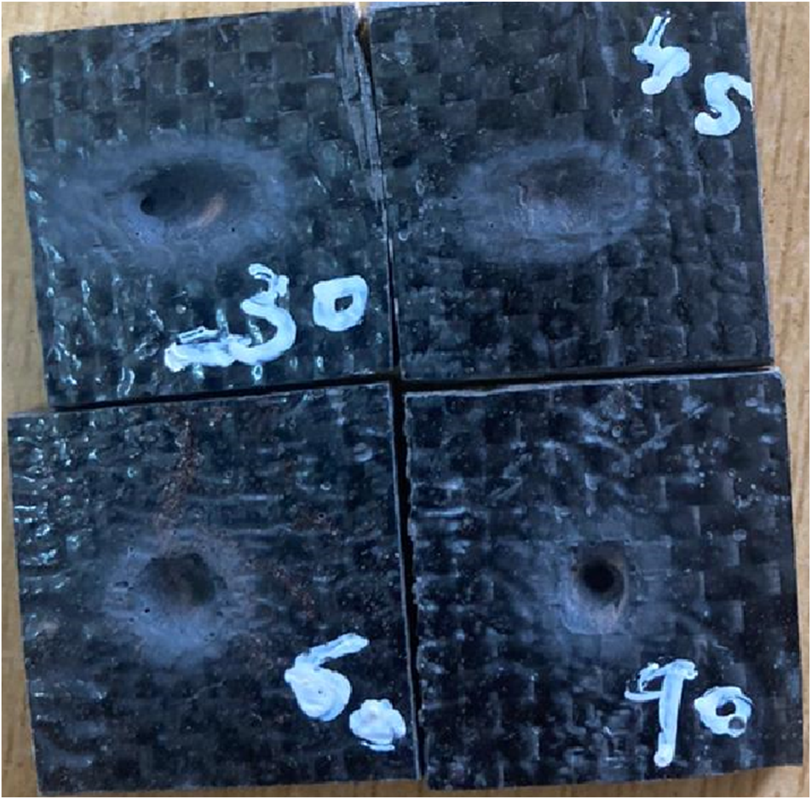
The test sample under macro vision indicates the crater formation over the exposed surface. Figure 11 shows the photo image of carbon – hemp fiber-reinforced composite material. At 90° the erodent scar found to be straight and deeper in the crater. The crater revealed in the form of deep hole and the profile is circular in shape. For the decreased angle the profile of the erosion scar revealed to elliptical. Based on the profile of scar the material loss are predicted with weighing balance. The difference in mass (g) before and after erosion are calculated and plotted in the Figure 12. For the maximum angle (90°) the depth of profile found to be increased and the material loss will be increase. The carbon with hemp fiber got maximum (0.03988 g) as well as minimum (0.019 g) in mass loss (g). At an angle of 30° all the test samples got minimum mass loss and decrease in angle 45°, 60° and 90° has revealed with increase in mass loss. It has been understood that the lower angle of inclination has minimum impact over material loss and the erosion found minimum. In the same case the basalt fiber and the combination of basalt + carbon fiber-reinforced composite is neutral in performance. The basalt fiber-reinforced composite has an average material loss of 0.0306 g and for the carbon fiber base composite has 0.0304 g in material loss. However, the average material loss in carbon + basalt base composite has a minimum material loss of 0.0228 g. From the material loss the erosion rate is calculated with the mathematical relation equation (3). Material loss (g) in different fiber reinforcement with reference to 2.5 g/min erodent flow and 100 m/s in particle velocity.

Figure 12 illustrates the material loss, measured in grams, for various fiber-reinforced composites including carbon-hemp, basalt, and carbon-basalt, subjected to erosion at different angles. A general trend observed is that material loss increases with the angle of inclination, reaching its peak at 90° for all composite types, and is minimized at the 30° angle. This pattern aligns with the increased normal impact forces at higher angles. Specifically, the carbon-hemp composite shows the highest variability in material loss, with the maximum recorded at 90° (0.03988 g) and the minimum at 30° (0.019 g). The basalt fiber composite exhibits a consistent pattern of material loss, averaging around 0.0306 g, indicating intermediate erosion resistance. On the other hand, the carbon-basalt composite demonstrates superior erosion resistance with the lowest average material loss of 0.0228 g, suggesting a synergistic effect of the combined reinforcements in enhancing durability against erosion.
To calculate the erosion rate, the difference in mass change and erodent flow rate ratio is calculated and plotted in the Figure 13. The erosion rate pattern is very close to the mass flow. The erosion rate is the reflection of mass loss on sample and erodent mass flow rate. The maximum erosion rate (0.0159 Δg/g) is noticed at 60° for the carbon – hemp fiber composite material. Similarly, the minimum erosion rate (0.0056 Δg/g) is recorded for the carbon – basalt – hemp base composite material. Carbon-basalt composites exhibit the least material loss and erosion rate due to balanced fiber-matrix synergy. Erosion rate (Δg/g) in different fiber reinforcement with reference to 2.5 g/min erodent flow and 100 m/s in particle velocity.
Figure 13 presents the erosion rate, defined as the ratio of material loss to erodent flow rate (Δg/g), for the same set of fiber-reinforced composites. The erosion rate patterns closely mirror the material loss trends observed in Figure 13. The carbon-hemp composite exhibits the highest erosion rate at 60° (0.0159 Δg/g), reflecting significant material removal under this condition. This indicates a critical angle where the combination of impact and sliding leads to maximum wear. The basalt fiber composite shows a moderate erosion rate, consistent with its average material loss, indicating balanced performance across different angles. Notably, the carbon-basalt composite achieves the lowest erosion rate (0.0056 Δg/g) at lower angles, reaffirming its superior erosion resistance and making it suitable for applications exposed to high-wear environments. Synergistic properties of carbon and basalt fibers improve wear resistance by distributing impact forces effectively.
The surface profile of the erosion samples is observed through the scanning electron microscope and the SEM images are presented in the Figure 14. The sample exposed at 90° angle of impingement has a regular profile. The impact of solid (hard alumina) particles has produced a deep crater and the result of erosion found to descale the matrix material and the fiber found pull out. The width of the crater measured from the erosion studies is approximately 1.8 mm in diameter. Subsequently, for the reduced angle the crater is not circular and the profile revealed in the form of ellipse. Profile of wear scar increased to 3.2 mm for 60°; 3.45 mm for 45° and 4.12 mm for 30° of inclination. The variation in wear scar is due to the sliding velocity and the particle shearing over the surface area. Similar profiles are observed in all other process conditions and the rate of wear is invariant. From the analysis, the erosive wear for the 45° and 60° found to be average in all the combinations. At 30° the wear and mass loss compared to the straight impingement. All the above the carbon – basalt fiber composite material has good performance compared to the other combination of materials. Erosion at lower angles forms elongated scars with less material loss due to increased sliding and reduced impact force. SEM image of the carbon – hemp fiber base composite subjected to solid particle erosion at different angle of impingement.
Figure 14 showcases SEM images of the carbon-hemp fiber base composite after erosion tests at different angles of impingement, namely 30°, 45°, 60°, and 90°. At a 90° angle, the SEM images reveal a regular, deep crater with a diameter of approximately 1.8 mm. The impact of alumina particles results in significant descaling of the matrix material and fiber pull out, indicating severe erosion. At a 60° angle, the wear scar becomes elliptical, with an increased profile diameter of about 3.2 mm. The combination of sliding and impact forces creates a moderate erosion pattern, with noticeable fiber damage and matrix removal. At 45°, the erosion scar elongates further to about 3.45 mm in diameter, highlighting increased sliding action and a mixed wear mechanism involving both impact and shearing. At the lowest angle of 30°, the scar profile reaches its maximum diameter of 4.12 mm, primarily due to sliding and shearing effects. Despite the larger scar profile, the material loss is minimized due to the reduced impact force, resulting in lower overall erosion. These SEM observations corroborate the material loss and erosion rate findings, providing visual evidence of the wear mechanisms at different angles.
Conclusion
The present study evaluated the mechanical properties, moisture absorption behavior, and erosion resistance of nine composite materials with varying fiber compositions, including treated hemp fiber, carbon fiber, basalt fiber, and consistent fillers (2.5% CaCO3 and 2.5% coconut fiber). The key findings are summarized as follows: ➢ Optimal tensile strength was observed in sample A2 (20% treated hemp fiber and 6% carbon fiber), demonstrating a 14% higher strength than B2 and 18% higher than C2. This highlights the importance of balanced fiber content, as excessive fiber leads to agglomeration and reduced strength. ➢ Sample B2 (20% treated hemp fiber and 6% basalt fiber) showed the highest flexural strength, 2% higher than C3 and 25% higher than A3. This indicates that the combination of treated hemp and basalt fibers maximizes flexural performance. ➢ B2 also exhibited superior impact strength, 10% higher than C3 and 35% higher than A3, suggesting that treated hemp and basalt fibers optimize impact performance. ➢ Optimal samples (A2, B2, and C2) absorbed moisture at a slower rate compared to other samples. Fillers such as CaCO3 and coconut fiber played a critical role in reducing water uptake by filling micro-voids and enhancing the matrix’s impermeability. Strong fiber-matrix adhesion observed in SEM images supported these findings. ➢ Erosion studies revealed increased material loss with the angle of inclination, peaking at 90°. The carbon-hemp composite showed the highest variability in material loss, while the carbon-basalt composite demonstrated the best erosion resistance. The lowest erosion rate (0.0056 Δg/g) was achieved by the carbon-basalt composite at lower angles, making it suitable for high-wear environments. ➢ SEM images of eroded samples showed significant material removal and fiber pull out at 90°, with elliptical wear scars at lower angles due to sliding and impact forces.
Overall, the study underscored the importance of optimal fiber-matrix ratios and effective filler use in enhancing mechanical properties, moisture resistance, and erosion resistance of composite materials. Sample B2 emerged as the optimal composite, demonstrating the best overall performance. These findings align with existing literature and highlight the potential of these optimized composites for various industrial applications.
Footnotes
Declaration of conflicting interests
The author(s) declared no potential conflicts of interest with respect to the research, authorship, and/or publication of this article.
Funding
The author(s) received no financial support for the research, authorship, and/or publication of this article.