
Abstract
For several decades, the disadvantages of traditional metallic rock and soil support structures have become increasingly prominent. As a result, it is urgent to seek lightweight, high-strength, durable and green economic substitute products made from the basalt fibre reinforced composites. Combining the two-phase material summing principle of composite material mechanics and the extension and application of Mohr–Coulomb strength criterion, the uniaxial tensile computing model of a cylindrical polymer specimen containing randomly distributed and discontinuous basalt fibres was established in accordance with the numerical simulation software Flac3D. Furthermore, the influence laws and intrinsic mechanism of the number of discrete fibres and different fibre distribution angles on the integral axial tensile properties of a cylindrical specimen with chopped basalt fibre thermosetting resin matrix composites were investigated and elucidated, and the stress–strain curve of basalt fibre thermosetting resin matrix composites were obtained. Consequently, the results have indicated that: i) the axial tensile strength of the polymer system can be enhanced through the incorporation of a moderate quantity of chopped fibres, with the resultant improvement typically not surpassing a 10% increment; ii) when the number of fibres has increased to the quantitative state, namely, the fibre density reaches 1.02 pieces/cm3 or more, the amplification of axial tensile strength of composite material will be controlled; iii) the fibre distribution directions, are maintaining a 0° parallel state to the axial direction of the specimen and the ones of load application, will ensure that the tensile strength of the composite can be sufficiently utilized. As the production process within the composite industry have become increasingly adept, the research results hold substantial value for further promoting the development, testing and optimizing application of various types of high-performance basalt fibre reinforced composite products.
Introduction
Research status of chopped basalt fibre reinforced polymer composites
Within the current context, the short fibre reinforced composites (SFRCs) has an inestimable development potential in lightweight structural design among the fields of civil engineering, aerospace, marine engineering, equipment manufacturing and biodegradation due to its higher specific strength, higher specific stiffness and particular design freedom.1–5 In addition, the excellent performances of fatigue resistance, corrosion resistance and oxidation resistance can be observed in this kind of material, also including a wide range of temperature adaptation, simple preparation process, lower production cost and sustainable utilization.1,6,7 The reinforcement phase of the SFRCs system is often randomly distributed in the entire continuous matrix as an independent and dispersed form to withstand the applied loads so that the comprehensive performance of the system can be enhanced, whose selected types of material are carbon fibres, glass fibres, aramid fibres, basalt fibres, etc. Compared with the use of other traditional fibre materials, the basalt fibres are equipped with significant advantages of mechanical properties and broad industry application prospects,7–10 such as the higher tensile strength and flexural elastic modulus, the larger limit tensile strain, the better fracture toughness and the superior ductility. On account of the advantages of economy and environmental protection, as well as abundant mass production, it will gradually promote the development and growth of fibre composite material industry, which will emerge as a friendly alternative to conventional fibres and a prospective reinforcement material Figure 1 and 2. Schematic diagram of a reinforced polymer system containing randomly distributed chopped fibres: (a) Cube; (b) Cuboid. Structure schematic diagram of each phase of the composite material system: (a) Structure components of composite material system; (b) Interface of two-phase media. Schematic diagram of relative shear slip of particles inside the rock material system: (a) Lateral restriction; (b) No lateral restriction. Schematic diagram of Mohr–Coulomb failure criterion in Flac3D.
36


In recent years, many scholars have carried out continuous and thorough experimental research on the application of chopped basalt fibres (CBFs) in the composition of new composite material systems or engineering structures, whose results demonstrate that the addition of quantitative CBFs can play a necessary role in optimizing the comprehensive performance of original materials or structural systems under given conditions. Liu et al. 11 incorporated CBFs into concrete structures to perform the bending test of composite beams, which was found that when 0.1% volume fraction and 20 mm long CBFs were added to reinforced concrete, the increase in the flexural strength of concrete could be around 20%, thereby obtaining the finding that the flexural performance during working stage were significantly improved compared with ordinary concrete beams. Cui et al. 12 studied the adhesive strength between chopped basalt fibre bundles and cement matrix through pull-out test and SEM analysis, and it was observed that when the embedding length of the fibres among the matrix reached 12 mm, the adhesion behaviour between basalt fibres and cement matrix exhibited most significant. Accordingly, the universal law of bonding failure of basalt fibre reinforced cementitious composites (BFRCC) under the influences of different fibre parameters could be summarized. Niaki et al. 13 experimentally explored the effects of CBFs addition on characteristics of fibre reinforced polymer concrete (FRPC) at different temperatures (under 250°C), whose results highlighted that the addition of 2 wt% basalt fibres increases the compressive strength and bending strength of concrete structures by 10% and 4.8%, respectively. In addition, the decay rates of residual strength of BFRPC structures at 50°C, 100°C, 150°C, 200°C and 250°C performed smaller than that of ordinary concrete structures. Thus, the presence of CBFs strengthened the partial mechanical properties and thermal stability of the original structure was verified. Zhang et al. 14 mixed the disperse basalt fibres and polyvinyl alcohol fibre (PVAF) into low-heat portland cement concrete (LHPC-C) in a certain proportion, and concluded the enhancing laws of compressive stress–strain relationship of LHPC-C containing hybrid fibres by means of mechanical property test and microstructure test. It was made clear that when 0.15% CBFs and 0.1% PVAF, 0.2% CBFs and 0.1% PVAF, 0.15% CBFs and 0.3% PVAF were added, respectively, the mechanical strength of concrete structures under the three conditions successively grew by 30.05%, 56.79% and 43.51% than the control group. Huang et al. 15 added CBFs as the filler into the epoxy resin coating to form the fibre skeleton, and verified the strengthening mechanism of the micro-convex bearing structure of the fibres on the tribological properties of the epoxy coating in virtue of dynamic mechanical analysis and SEM method under the conditions of drying, corrosion and UV ageing, and the results indicated that the tribological performance of the composite coating containing 2 wt% basalt fibres performed the best compared to pure epoxy resin, and the wear rate after friction in saltwater would be reduced by 76.03%. Mercuri et al. 16 explored the variations using laboratory tests in the diagonal shear strength of two-end masonry walls formed by reinforcing mortar incorporated with chopped fibres in three different adding modes, and displayed that when reinforcing mortar containing basalt fibres and glass fibres were used for double layer reinforcement, the shear strength rose by 218% and 194% compared to the unreinforced conditions, respectively, verifying that the disperse basalt fibres among the mortar matrix became a more effective and sustainable way to reinforce the existing masonry structures in seismic areas. Zhang et al. 17 examined the effects of CBFs on the fracture performance of concrete with decreased calcium content by conducting accelerated leaching and the three-point bending (TPB) tests on single-notch TPB specimens, and identified that adding CBFs with a length of 6 mm (i.e. a length-to-diameter ratio of 400) and a volume dose of approximately 0.35% could improve the integral performance of concrete by nearly 17.68%, revealing the mechanism by which CBFs enhance the resistance of concrete to dissolution damage and cracking.
Research status of basalt fibre reinforced resin matrix composites
Indeed, the fibre reinforced polymer composites are generally composed of multi-phase components, and acquires excellent performances that the original constituents have not been manifested through the mutual correlation and complementary advantages of each part. Although the larger strength, higher stiffness and soft texture can be examined in the fibre dispersed phase, it will adequately realize the reinforced characteristics of the original system mechanical properties under the load, wrap, support and protection of the continuous matrix with favourable bond compatibility, namely, the reinforced fibres are beneficial to transfer the external imposed stresses from the polymer matrix with weaker stiffness to itself in order to improve the integral strength of the composites.
In terms of the discontinuous reinforced polymers, the composite will be crucially affected by the matrix phase strength. More specifically, the extrinsic loads are usually dispersed and transmitted as the form of shear deformation during the entire loading process to prevent the fibres from being damaged and corroded. In this case, the contact transition part of between the fibres and the matrix is normally defined as ‘interface’. 18
As the matrix of composites, the resin needs to fulfil the requirements of higher strength, stiffness and toughness, and can orient and position the fibres into a whole, as well as satisfying the superior processing formation technology standards. 18 Epoxy resin and its thermosetting polymers, integrate their remarkable physical and mechanical properties, heat resistance, electrical insulation, chemical resistance and synthetic processing capabilities, are widely applied in emerging and hot industries, such as automobile manufacturing and aerospace, which have become the optimized matrix material for use of composites.19–22 In fact, the molecular structure of epoxy resin contains unique and abundant active and polar groups with wide varieties and various brands that can exhibit numerous high-quality properties, and couples with diverse curing agents, accelerators, modifiers, additives and other fillers, so as to match and form epoxy curing polymers with different types and unique features, which can almost meet the requirements of various processing properties and is unmatched and surpassed by other thermosetting resins. 23
Thermosetting resins containing epoxy groups are basically insoluble or cannot return to the uncured state after curing through chemical catalysts or accelerators and other applicable ways. The liquid state can be mostly emerged in epoxy resin with flexible applying technologies, convenient moulding and high cohesion strength before curing, which has good fluidity and can be effectively bonded with various materials. At present, the most productive and broadly used variety in the composite material industry should be bisphenol-A epoxy resins (diphenol propane epoxy resins), which can tremendously adjust the viscosity of the resin system, followed by glycidyl amine epoxy resins. 24
In general, the composite material, which emerged in the mid-20th century, represents one of the focal points of contemporary scientific and technological research, which typically denotes the amalgamation of two or more solid-phase substances displaying markedly different physical or chemical properties, achieving through advanced artificial material synthesis techniques, whose integration will yield a macro or micro material system endowed with novel superior properties that diverge from the intrinsic characteristics of the constituent elements. 25 In line with this principle, the basalt fibres with high strength, high modulus, light weight and green economy are selected as the reinforcement phase, while the epoxy resin curing polymers with lower strength, lower modulus, higher cost, highlighted bond performance, and reliable design techniques are taken as the matrix phase, the basalt fibre reinforced polymer composites (BFRPCs) can be assembled subjected to the specific conditions to gradually innovate and applied in various progressive and sophisticated fields based on the potent incorporation of both complementary advantages. 26
In view of the application of BFRPCs in the field of engineering structures using composites, some recent related research and demonstration have been made. Sun et al. 27 prepared two sets of unidirectional BFRPCs products with different fibre diameters by dipping and wrapping technique as the potential structural material for Type III storage tanks in thermally insulated containers of low temperature pressure, and tested the mechanical properties at room temperature and liquid nitrogen temperature (77K) through the SEM analysis, whose results demonstrated that the fibres and resin matrix displayed better compatibility at lower temperature and it was ascertained that the flexural strength and compressive strength of unidirectional BFRPCs with fibre diameter of 13 μm at 77K increased by 52.3% and 69.1% compared with that at room temperature, respectively, thereby verifying that the partial mechanical properties of unidirectional BFRCs were enormously improved compared with that at room temperature, which has created the possibility of lower temperature application of BFRPCs. Chen et al. 28 studied the changes of mechanical properties and stability of pultruded basalt fibre reinforced polymer (BFRP) pipes under axial compression loads based on the differences in slenderness ratio and cross-section shapes through laboratory tests, which was evidenced that the compressive strength and compressive elastic modulus of BFRP short tubes with slenderness ratio ranging from 20 to 150 could reach 122.36 MPa and 40.39 GPa, respectively, and proposed the two design-oriented three-stage theoretical models, as well as deriving the stability equations for predicting the compressive strength of slender BFRP pipes. Zhou et al. 29 investigated the failure mechanism and practical factors affecting the fatigue properties of basalt fibre reinforced polymer (BFRP) bolts by means of multiple sets of laboratory tests and SEM analysis, whose results indicated that the fatigue life of bolts was controlled by the cross-section forms of bolts and was simultaneously affected by the anchoring methods and fabrication technologies, and it was reported that the static anchoring efficiency of round rib anchor cable could reach 110% after two million cycles among them, which has revealed the fatigue failure modes and failure mechanism of BFRP bolts and verified the static properties of BFRP bolts with circular section under the fatigue loads. Zhou et al. 30 explored the bond performance of BFRP bars and seawater sea sand concrete by employing the laboratory accelerated ageing test of specimens immersed in seawater solution, which was pointed out that the bond strength of deep-ribbed BFRP bars denotes 5.4% and 20.6% lower than that of shallow-ribbed and sand-coated BFRP bars after 120 days of immersion in seawater at 40°C, respectively, revealing the degradation mechanism of the adhesive strength of BFRP bars of various cross-section types and the change laws of bond performance with exposure time. Liu et al. 31 studied the degradation mechanism of BFRP bars in simulated marine concrete pore solution under alkalinity gradients with different given Ca(OH)2 contents through experiments, which was brought to light that reducing the pH value of pore solution from 13.24 to 11.07 could prolong the service life of BFRP bars in concrete structures by 60 times, and predicted its long-term performance in practical application environment. Zhou et al. 32 studied the change rules of residual properties of different kinds of FRP materials within the high temperature range of 80 ∼ 210°C through macro single shear fracture test and microstructure characterization, and found that the effective bonding length of FRP bonded wood would continue to increase with the exposure temperature rising to 210°C. The degradation mechanism of integrated system of basalt fibre composite bonded woods in high temperature environment was revealed. Aljidda et al. 33 adopted the laboratory tests to investigate the change conditions of flexural properties of 10 RC one-way slabs installed with BFRP bars on the near surface (NSM) under the function of four-point loads until failure. The test results demonstrated that the ultimate load of RC slabs with reinforcement ratio of 0.48 and 0.95% increased by 51∼123% and 21∼44%, whereas the ductility index went up by 10∼53% and 29∼79%, respectively, which proved that the NSM-BFRP reinforcement could significantly improve the flexural performance of RC slabs.
Existing problems and research content
In summary, the contemporary society is generally seeking green and environmentally friendly high-performance materials for engineering construction to resolving practical issues. The use and popularization of basalt fibre products in the field of engineering and materials science display notable advantages, which has gradually stimulated strong research interest and abundant creativity among individuals, and will enable it an emerging hot trend to replace the original metal and traditional fibre materials. Tremendous investigations have been conducted on the application of basalt fibre reinforced composites in the field of engineering structures by domestic and foreign scholars, which have attained plentiful achievements. Currently, there are still the following aspects that subject to further refinement:
(1) The relevant researchers predominantly adopted the advanced scientific experimental means to explore the variations of flexural behaviour, shear behaviour, fatigue property, bond strength, thermal stability, durability, tribological properties and so forth of the composite material system under the stated ambient conditions (temperature, load, speed and alkalinity.) after the addition of chopped basalt fibres in the novel engineering practices, whereas its variation rules and the intrinsic mechanism of tensile properties remain to be thoroughly studied; (2) In consideration of the researches of resin matrix composites, the practical application pattern of involving basalt fibres primarily belongs to the type of continuous strips manufactured by pultrusion moulding process, whilst the discontinuous and discrete chopped forms, typically adopted as the auxiliary matrix phase of fillers, are infrequently used, so this presents the opportunities for further exploration on the specific strengthening mechanism of the composite material system formed by the chopped basalt fibres and the thermosetting resin; (3) Numerous studies on composite engineering structures concentrate on the given mechanical response alterations of integrated systems, and pay little attention to the prediction of stress–strain curve laws in polymer materials themselves. Therefore, it is imperative to carefully understand the variation characteristics of stress–strain curve of polymer materials during deformation.
In the field of underground engineering, the long-term utilization and incorporation of metal support structures are commonly employed to improve the bearing capacity and stability of rock and soil mass, which can effectively address the complex geotechnical deformation problems. Nonetheless, the metal support structures are difficult to adapt to complex environmental changes and gradually reveal the limitations of use, which potentially contribute to the severe safety incidents. In the meantime, the basalt fibre composite materials have begun to capture the attention of underground space research scientists because of their favourable properties. By means of the in-depth investigation and comprehension of the mechanical properties of basalt fibre composite materials, it is feasible to develop innovative high-performance alternatives and promote their application in geotechnical engineering support, solving specific practical engineering problems and anticipating the generation of substantial economic value and extensive social benefits.
The aim of this study is to investigate the changes of axial tensile properties of the cylindrical specimen within the chopped basalt fibre thermosetting resin matrix composites from the initial to the ultimate tensile state in virtue of theoretical analysis and numerical simulation under the circumstances of different fibre number and fibre distribution angles in a specific volume under the static load and normal temperature and pressure, including clarifying the induced internal mechanism. Furthermore, the variation characteristics of the stress–strain curve of composite cylindrical specimen during the tensile process will be explored. In this research, the cylindrical composite specimen with the identical diameter and height will be taken as the research object, and the curing system of pure cylindrical epoxy resin without discrete fibres will be selected as the reference object. In accordance with the analysis and utilization of the two-phase material summing principle in composite mechanics and the extension and application of the Mohr–Coulomb strength criterion in rock mechanics, the uniaxial tensile computed model of a standard cylindrical specimen of the thermosetting resin matrix composites with equal diameter and height is planned to be established by the finite difference software Flac3D, whose embedded cable structure elements in the software are intended to program and assign parameters to generate quantitative randomly distributed discontinuous basalt fibres inside the specimen. A self-designed calculation program will be employed to apply a constant rate of different sizes to the outward normal direction of the loading end circular cross-section of the cylindrical specimen. Moreover, the graphical representation results of the stress–strain curve variations at any point along the axial direction can be attained by means of monitoring, as well as obtaining the important mechanical indexes of tensile properties of the composites in the field of engineering application, which will be beneficial to foster the promotion and application of basalt fibre products made of different forms and various design processes, thereby propelling the vigorous development of green high-performance basalt fibre composite materials industry.
Fundamental theories
Two-phase material summing principle
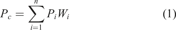
With respect to the two-phase composite system, the integral mechanical properties and physical properties of the composites are determined by the weighted summation of the corresponding index values of each component material according to their respective volume fractions,
34
which can be alluded to as ‘the two-phase summation weighting principle’, represented by a general expression, that is
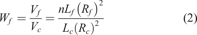
Hypothesizing that the radius, length, volume, elastic modulus and density of the single fibre in the standard cylindrical specimen of the chopped basalt fibre thermosetting resin matrix composite can be indicated as
It is assumed that the density, volume fraction and elastic modulus of epoxy resin matrix can be expressed as
Supposing that the radius, height, volume, elastic modulus and density of the cylindrical polymer specimen can be defined as
In line with the geometric relationship of the disperse distribution of multiple chopped fibres in the cylindrical polymer specimen without considering the proportion of inclusions, we can get

On the basis of the two-phase material summing principle, that is


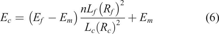

Based on the design procedure of the elastic modulus

Extension and application of Mohr–Coulomb strength criterion
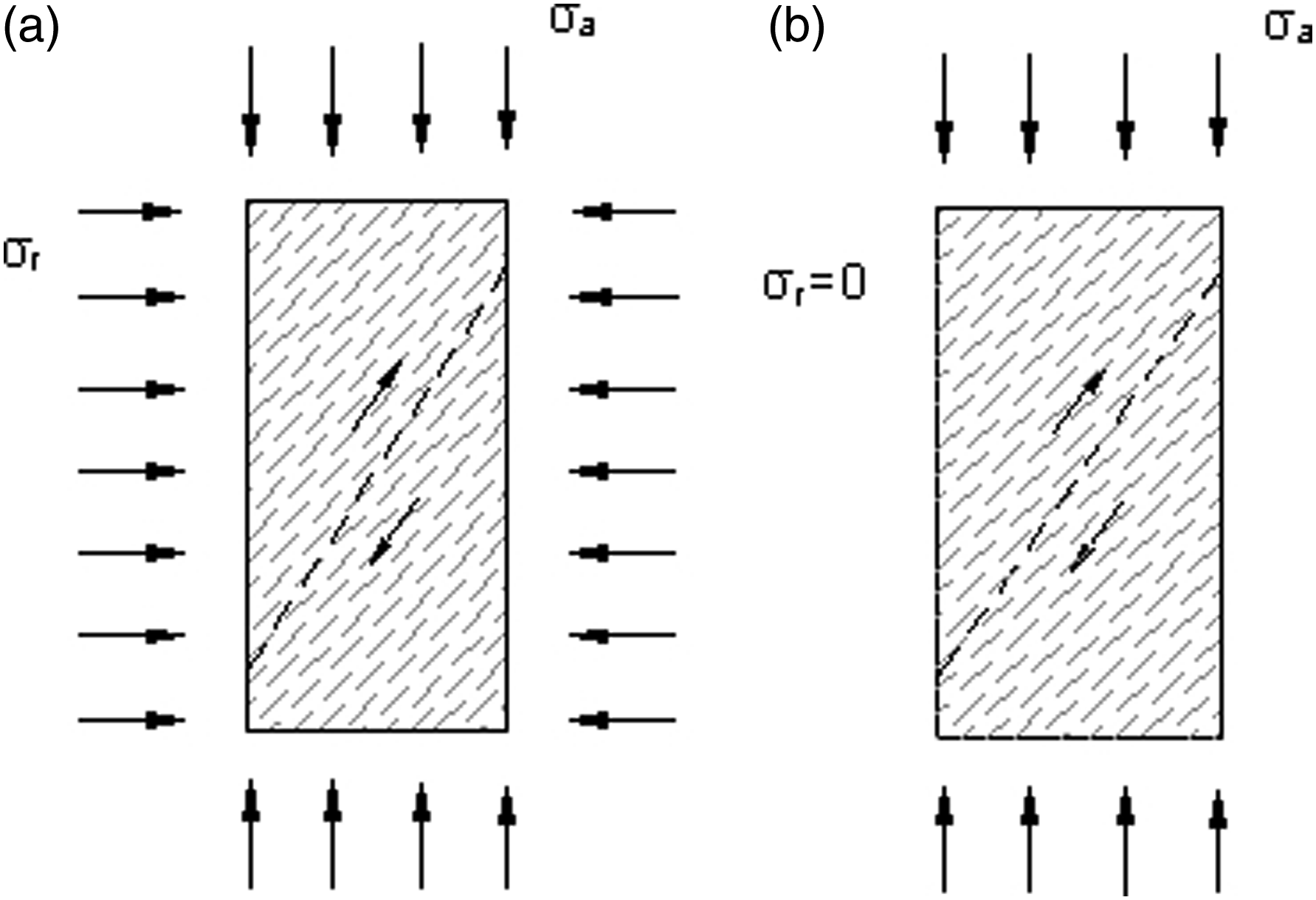
To be more specific, the physical background of the application of Mohr–Coulomb strength criterion in rock mechanics refers to that certain cohesive and frictional properties can be discovered in the rock,
35
which are reflected in the parameters of expression, namely, the cohesion
Normally, the rock cohesion
In addition, the internal friction angle of rock

As a matter of fact, the thermosetting resin matrix in the composite is involved with certain thermoplasticity before curing, and the lower mechanical strength has emerged. Nonetheless, after adding the filler to form the formulated resin curing system, of which the more active polar groups will give the cured epoxy resin much higher adhesive strength, 23 and embrace its own unique cohesion strength in the molecular dense structure, so the matrix phase in the material system is provided with fairly strong bonding characteristics. Under the impact of external loads, the shear stresses will be distributed and transferred inside the cured epoxy resin, so as to enable the particles with rough surface to generate the effects of relative slip, mutual embeddedness and interlocking, which has reflected certain frictional characteristics.
Since the Mohr–Coulomb strength criterion is extensively applied in the field of geotechnical engineering, whose generalized nature is to describe the common cases that a material system will get failure when the ratio of shear stress to normal stress on the internal shear plane inside the material reaches the maximum under the influences of external forces.
Notably, there are numerous similarities between rock material and formulated resin matrix material during use: (1) both of them belong to loose sediments undergoing natural weathering or artificial peeling, but they all can be regarded as the continuous media based on the analysis of their own geometric dimensions; (2) the anisotropic characteristics are usually equipped with them, exhibiting different physical and mechanical properties in various directions; (3) both of them generally manifests a certain inhomogeneous features due to the natural environment or fabrication process; (4) the denser molecular structures of these two materials can generate the bonding force to improve the integral strength of the system and display specific cohesive and frictional characteristics when subject to external forces, which accords with the physical background of the application of Mohr–Coulomb strength criteria in a broad sense.
Consequently, the tensile yield expression of Mohr–Coulomb strength criterion can be approximately simplified as being suitable for the numerical study of tensile properties of chopped basalt fibre thermosetting resin matrix composite. In this research, FLAC3D is adopted for numerical simulation of standard cylindrical polymer specimen, and the embedded Mohr–Coulomb criterion in the software is represented by the principal stress
Zone safety degree based on Mohr–Coulomb strength criterion
Along with the progress of numerical limit analysis methods of rock and soil mechanics, it is of vital importance to determine whether the research subjects have completely entered the ultimate failure states under the specific conditions in a scientific and simple way. Based on the Mohr–Coulomb strength criterion (as depicted in Figure 5) and simultaneously taking the tensile and shear failure of the material system into account, the quantitative zone safety degree index with tensile strength was adopted in this paper,
37
that is Mohr–Coulomb strength criterion.

Numerical simulation
Establishment of tensile model for standard cylindrical polymer specimen
In this paper, the uniaxial tensile computing model of the cylindrical specimen was established by the software Flac3D (see Figure 6(a)), whose diameter and height were set at 50 mm. The Mohr–Coulomb constitutive model was adopted to participate in the numerical simulation. In the meantime, the self-made three-dimensional calculation program and the cable structural elements embedded in the software were employed to assign values to the relevant parameters to refer to and generate randomly distributed chopped basalt fibres within the specimen (as depicted in Figure 6(b)). Additionally, five monitoring points were arranged at each fibre from top to bottom in order to record and characterize the variation trends of axial stress in various tensile states. Computing model: (a) Geometric model of cylindrical specimen; (b) Randomly distributed chopped basalt fibres in the geometric model (100 fibres with distribution angle of 15°).
Admittedly, there are tremendous factors affecting the axial tensile properties of a cylindrical specimen with thermosetting resin matrix composite. Nevertheless, the current round of numerical simulation is planned to concentrate on the influence of the number of fibres and distribution angles on its strength by using the variable-controlling approach, mainly considering the following two sets of circumstances: (1) the distribution angles of fibres were arranged in the direction of counterclockwise rotation 45° around the z axis, and 0, 100, 200, 300, …… 1000 fibres were successively generated inside the specimen (increasing in arithmetic sequence with a tolerance of 100); (2) the distribution angles of fibres were orderly arranged in the direction of counterclockwise rotation 0°, 15°, 30°, 45°, …… 90° around the z axis (rising in arithmetic sequence with a tolerance of 15°) with creating 100 fibres for each case inside the specimen.
On the basis of establishing the original uniaxial tensile geometric model of a cylinder, the superficial velocity V1, V2, V3, V4 and V5 with the constant rates of 1.0e-03, 2.0e-03, 3.0e-03, 4.0e-03 and 5.0e-03 mm/step were applied in sequence along the outward normal pointing of the loading end circular cross-section of the chopped fibre polymer specimen incorporating 100 fibres with distribution angles of 45°, so as to obtain the stress–strain curve relationship of the formed solid polymer material.

Grouting material parameters of the cable element. 36

Material parameters of cylindrical polymers containing 100 fibres.

In simpler terms, the boundary condition of the model was set as one fixed end and one free end. The step-load test was adopted as the load pattern, and the tensile loads were imposed on the normal direction outside the circular section of the specimen free end as the form of surface force without considering the cross-section friction (as exhibited in Figure 7). On top of that, five critical recording points were arranged in proper order along the axial direction of the specimen from the stiff end to the loading end (see Figure 8). Schematic diagram of imposed tensile loads on circular cross-section of the polymer specimen free end: (a) Tensile integrity; (b) Tensile failure. Tensile geometry model of a cylindrical polymer specimen with critical recording points: (a) Elevation view; (b) Axial section view.

Furthermore, whether the plastic zone of the specimen central section connected or not was adopted as the failure criterion, and the axial tensile loads was applied step by step to the free end section of the computing model until the model reaches the ultimate equilibrium state. In this case, the load of preceding step can be defined as the ultimate load when the specimen model got failure. Accordingly, the specific numerical simulation flow chart for determining the ultimate tensile load of the polymer specimen whereby the overload method is displayed in Figure 9. Flow chart of numerical simulation for determining the ultimate tensile load.
Eventually, the self-complied postprocessor in accordance with the Mohr–Coulomb strength criterion could be employed to further determine and verify the ultimate tensile state of the cylinder sample. The axial stress and deformation values of each recording point of the cylinder specimen were monitored and obtained via the self-programmed post-processing calculation program, and the strain values of each point were attained by calculating the ratio of displacement difference of the point induced by different loading forces at the previous and latter stages and the specimen height.
Stress–strain curve law of the solid polymer specimen containing fibres
In fact, the arbitrary point along the axial direction of the cylindrical polymer specimen was selected as the monitoring point, and the stress–strain curve of this point under various loading rates could be acquired by adopting the self-programmed calculation program (see Figure 10(a)). When the axial strain value increases from 0, the axial stress value will first rise from 0 to reach the peak. Afterwards, it will gradually decrease to the bottom part, and then rebound and jump after a short period of stability. This is basically consistent with the variation trend of the graphical representation of the stress–strain curve of solid polymers depicted in the literature
41
(as exhibited in Figure 10(b)). (a) Tensile stress–strain curve of the axial monitoring points of cylindrical polymer specimen with 100 chopped fibres of 45° distribution angle at different loading rates; (b) Stress–strain curve of general solid polymer material.
41

No matter how the number and distribution angles of the chopped fibres inside the specimen change, the typical tensile stress–strain curve (see Figure 11) of a cylindrical solid polymer specimen at any points along the axial direction will generally goes through the phases of linear elasticity (section OA), yield (section AB), strain softening (section BC), smooth flow (section CD), strain hardening (section DE) and brittle fracture (after the point E), which has vividly reflected the deformation process of the polymer specimen from the initial state to the limit state. Typical tensile stress–strain curve of the cylindrical solid polymer specimen.
As consequence, the solid polymer material containing fibres will deform before the yield stage and can be completely recovered after unloading. After the yield point (i.e. the point A labelled in Figure 11), it will enter the plastic phase and the permanent deformation will occur. After the accomplishment of the yield stage, the stress–strain relationship presents diversity: the strain value continues to increase, whereas the stress value will decrease, stabilize and grow up successively until the final fracture emerges. Owing to the multiple and various structure and shape of the components forming polymers, which are prone to be affected by the physical environment temperature and tensile rates, the stress–strain curve of different materials vary among characteristics, but roughly five types were concluded, 42 from which the corresponding mechanical indexes can be obtained as the basis for the tensile process design of composites.
Influence laws of fibre number on tensile properties of the specimen
In accordance with the numerical simulation results of cylindrical polymer specimen with different number of fibres in the initial and ultimate tensile states (as depicted in Figure 12, Figures 13 and 14), when the magnitude and direction of all fibre distribution angles remained consistent, the ultimate tensile load value of the specimen would continuously increase and the size maintained stable in the range of 1.13 kN ∼ 1.19 kN as the number of fibres rose within a limited range (0∼1000 fibres) and the air volume inside the cylinder decreased, and the growth rate would slow down dramatically when the number of fibres exceeded 100. In the initial tensile state, the deformation of the specimen was equivalent to 0 since one end was constrained and the load imposed on the free end manifested smaller. When reaching the ultimate state, all the growth inflection points of axial deformation and strain values of the rest of points started to emerge when covering 100 fibres, except for the monitoring point 1, which was restricted to move all the time. Line graph of variations of ultimate tensile load of the cylindrical specimen incorporating different number of chopped fibres. Line graph of changes of axial strain in the ultimate tensile state of the monitoring point of the circular section at the loading end of the cylindrical specimen containing different number of chopped fibres. Line graph of variations of axial stress at each monitoring point of cylindrical specimen incorporating various number of chopped fibres: (a) Initial tensile state; (b) Ultimate tensile state.


When the specimen was located in the ultimate state and the number of fibres kept identical, the axial deformation and strain values of each point would successively go up from bottom to top according to the order of the monitoring point label (see Figure 8, the same as the following contents). The maximum axial deformation value of 0.031 m and the maximum axial strain value of 0.493 both appeared at the monitoring point 5 when incorporating 100 fibres. In contrast with the same condition when the number of fibres equaled 0, the increases were about 3.8% and 4.0%, respectively.
At the time when the specimen was entering the ultimate tensile state, the axial deformation values of the points 2, 3, 4 and 5 all reached the highest peak when containing 100 fibres except for the fixed point 1, which were 0.006 m, 0.012 m, 0.025 m and 0.031 m, respectively. In comparison with the condition of 0 fibre, the rises indicated 2.98%, 3.14%, 3.76% and 3.76%, respectively. Nonetheless, the maximum axial strain values of each point displayed 0.098, 0.195, 0.394 and 0.493, respectively, which were attained when the number of fibres was 100. Compared with the case of adding 0 fibre, the rough increments exhibited 3.00%, 3.18%, 3.81% and 3.96%, respectively. Hence, it could be found that the axial deformation and strain growing rate of each monitoring point with the increase of the number of fibres generally tended to go up progressively from inside to outside of the specimen initiating from the fixed end, and all of them realized the maximum increment at the monitoring point 5. Besides, the larger rise could be examined in the axial strain of the same case.
When the specimen was turning into the initial tensile state, the axial stress values of each monitoring point would increase remarkably as the rise of fibre density in the finite volume, and began to fluctuate up and down until the addition of more than 100 fibres, showing an indented pattern. In addition, the minimum axial stress value of 0.116 MPa at all points occurred when incorporating 0 fibre, whereas the maximum axial stress value of 0.120 MPa mostly emerged when the number of fibres equaled 100 (the maximum value of the monitoring point 4 was located at the fibre number of 400), whose stress had risen by nearly 3.5%.
When the specimen was getting into the ultimate state, the variation trends of the axial stress values of each monitoring point with the number of fibres were similar to the initial tensile state. To be more specific, the inflection points of increase were located at the fibre number of 100 as well. In this case, the maximum value depicted 0.586 MPa, 0.589 MPa, 0.592 MPa, 0.597 MPa and 0.595 MPa in the order of each point label from bottom to top. Thereinto, the maximum values of the monitoring points 3 and 5 were attained at the inflection points, whilst the remaining values were achieved at the fibre number of 500, 400 and 400, respectively. Thus, it could be seen that the maximum axial stress value of the whole specimen in the ultimate state was 0.597 MPa obtained at the monitoring point 4 when the number of fibres equaled 400, which was significantly increased compared with the minimum and maximum values in the initial state.
At the time when the specimen was passing into the ultimate tensile state, the minimum axial stress values of each monitoring point were acquired when covering 0 fibre, whose values of each point in the order from bottom to top exhibited 0.579 MPa, 0.578 MPa, 0.572 MPa, 0.572 MPa and 0.556 MPa, respectively. In contrast to the former, the maximum values of each case under the same conditions went up by 1.21%, 1.90%, 3.50%, 4.37% and 7.01%, respectively. At that point, the axial stress growth rates of each monitoring point increased from inside to outside initiating from the fixed end with the rise of fibre density in a specific volume, which would reach the amplification peak at the monitoring point 5.
In summary, adding inorganic chopped basalt fibres with a quantitative number to form a new standard cylindrical polymer specimen in relation to the pure formulated resin curing system, whose axial stress, deformation and strain values at each axial point indicate slightly higher than that of the original system under the same conditions, namely, the axial tensile strength will be increased in a small range and the axial tensile stiffness will be degenerated in a small scale. The proportion of improvement or degeneration is generally not more than 10%. Although the inclusion of quantitative number of fibres is conducive to the improvement of axial tensile strength of the polymer specimen, the growth rate of strength improvement percentage will be limited with the increase of fibre number. In general, each property parameter in the initial stage of fibre number growth under different tensile states will reach the extreme values, whose inflection points usually emerge at the fibre number of 100 (i.e. the fibre density achieves 1.02/cm3).
Influence laws of fibre distribution angles on tensile properties of the specimen
On the basis of the numerical simulation results of the cylindrical polymer specimen with fibres of different distribution angles at initial and ultimate tensile states (as depicted in Figure 15, Figures 16 and 17), when the fibre density remained constant in a finite volume, the ultimate tensile load value of the specimen would continue to decline with a decreasing fall and maintain stable in the range of 1.173 kN ∼ 1.178 kN with the increase of fibre distribution angle within a specific scope (0°∼90°), and finally remained basically unchanged in the range of 75°∼90°. Besides, the inflection points of decreasing fall occurred when the angle was 15° and 75°, respectively. When the specimen was located in the initial tensile state, the deformation equaled 0 because the movement was restrained at one end and the loads applied at the free end exhibits smaller. When reaching the ultimate state, the axial deformation and strain values of the remaining points stabilized between 0.006∼0.031 m and 0.02∼0.50, respectively, except for the monitoring point 1, which was fixed all the time. More specifically, the peak values of axial deformation and strain of each point were realized when the distribution angle was equivalent to 0°, while most of the minimum values were obtained when the angle ranged from 75°∼90°. Line graph of variations of ultimate tensile loads for the cylindrical specimen with chopped fibres of different distribution angles. Line graph of axial strain variations of the monitoring point of the circular section at the loading end of the cylindrical specimen of chopped fibres with different distribution angles in the ultimate tensile state. Line graph of axial stress variations at each monitoring point for the cylindrical specimen with chopped fibres of different distribution angles: (a) Initial tensile state; (b) Ultimate tensile state.


At the time when the cylindrical specimen was entering the ultimate state and the distribution angles of each fibre kept identical, the axial deformation and strain values of the monitoring points increased gradually according to the sequence from the fixed end to the loading end (see Figure 8, the same as the following contents). Compared with the case of no fibre addition, the axial peak deformation value obtained at the angle of 0° of all points (except the monitoring point 1) went up by 3.29%, 3.45%, 4.68% and 4.51%, respectively, whereas the axial peak strain rose by 3.31%, 3.52%, 5.06% and 4.95%, respectively. Thus, it could be found that the increase amplitude of each peak value at the monitoring point 4 took the highest rank, and the one of axial strain performed more remarkable than that of axial deformation under the same conditions.
When the specimen was turning into the initial tensile state, the axial stress values of each monitoring point fluctuated repeatedly with the increase of the fibre distribution angle values. Following the order initiating from the constraint end inside and out, the monitoring points 1, 2 and 5 all reached the maximum value of 0.12 MPa at the distribution angle of 90°, whereas the monitoring points 3 and 4 realized the peak values at the distribution angle of 45° and 0°, respectively. In addition, the minimum axial stress value of 0.119 MPa at each point was mostly obtained at the angle of 75° (except the monitoring point 5 at 60°). In contrast with the condition without fibres, the axial stress peak values of each point went up with little differences between each other by 3.41%, 3.28%, 3.17%, 3.20% and 3.40%, respectively, whose rise rate of the monitoring points 1 and 5 manifested the most significant.
At the time when the specimen was getting into the ultimate tensile state, the variation trend of the axial stress values of each monitoring point was similar to that of the initial tensile state with the growth of the fibre distribution angle values. Nevertheless, the slightly wider fluctuation range with up and down emerged, which was reflected in the figure, namely, each change line hardly converged or intersected. Most of the monitoring points attained the peak values of axial stresses at the fibre distribution angle of 0° (except the monitoring point 5, which obtained the maximum value of 0.596 MPa when the fibre distribution angle was 90°). According to the order of the points 1, 2, 3 and 4, the values indicated 0.590 MPa, 0.593 MPa, 0.595 MPa and 0.597 MPa, respectively. Under the same conditions, the axial stress values of each point increased by 1.82%, 2.70%, 4.05%, 4.39% and 7.16%, respectively. Compared with the condition without fibres, the variations of the growth rate exhibited significant. However, the minimum axial stress values of each point were acquired at different distribution angles, which were achieved at 45°, 60°, 90°, 75° and 15° in line with the order of points, among which 0.584 MPa at the monitoring point 1 became the smallest one in the various discussed cases.
Consequently, when the cylindrical polymer specimen was mixed with a constant number of chopped fibres, and the distribution of each fibre was kept as parallel as possible to the axial direction of the specimen and the loading direction of the force, the tensile strength of each axial point of the composite system would be sufficiently utilized when reaching the ultimate state.
Mechanism analysis
In order to clarify the induced intrinsic reasons of the influence laws obtained by numerical simulation concerning the geometric model of a cylindrical polymer specimen under the uniaxial tension, it is necessary to understand the transferring sequence of tensile stresses of the cylindrical specimen with chopped fibre reinforced composite during the environment of static load, and normal temperature and pressure.
To investigate the loading process of composite, it cannot be simply regarded as uniform stress of homogeneous system, while the complexity of contained multiple phases and the transferring stress path between each phase should be adequately considered. In relation to the cylindrical specimen studied in this paper, when the tensile load is applied to the circular section of the loading end of the specimen, the dispersed phase of internal random fibres will not be directly affected. Indeed, the periphery wrapped resin matrix material is initially put stress, and after that it will transfer to each single fibre via the interface between the matrix phase and the dispersed phase. 43
At this time, the tensile stress has been attenuated by the participation and random distribution of the resin matirx strength. Since the tensile modulus of fibres remarkably manifests higher than that of resin, each single fibre has not completely reached respective ultimate strength when the polymer specimen is usually on the verge of failure, namely, the superior properties of each point of material have not been entirely utilized.
44
Besides, it can be supported by the numerical simulation process according to Chapter 3 as well, and the results are depicted in Figures 18 and 19. Fibre stress state diagram at tensile failure of the specimen (including 100 fibres with distribution angle of 0°): (a) Displayed matrix; (b) Hidden matrix. Line graph of change of axial stress values at each monitoring point of single fibre in each tensile state (containing 100 fibres with distribution angle of 0°).

As previously discussed, the material tensile strength of each axial point of the cylindrical polymer specimen covering 100 fibres with distribution angle of 0° is prone to get sufficient exploitation. In this case, the axial stress values of each monitoring point of any single fibre inside the specimen in each tensile state during the loading process were collected and plotted as a variation curve, as exhibited in Figure 19.
As can be seen from the variation trend of each broken line in Figure 19 (two sets of polylines at the monitoring points 1, 5 and the monitoring points 2, 4 almost coincide each other), with the continuous loading of axial tensile force, the axial stress value of each point will indicate an approximately complete linear increase, and the extreme values will be obtained at the beginning and end points. Under the same tensile state, the axial stress value of the monitoring point 3 always holds the largest rank. According to the incremental point number sequence from the fixed end to the loading end, the stress value of each point is roughly symmetrical with respect to the monitoring point 3. During the ultimate tensile state, the axial stress value of 1.46 GPa at the monitoring point 3 takes the greatest one among all points through the whole loading process. Meanwhile, the axial stress value of the monitoring points 1, 5 only equals 0.56 GPa, whilst the ultimate tensile strength of basalt fibres usually values range from 3.0∼4.8 GPa.9,38–40 Therefore, the axial stress values recorded at each monitoring point of fibres in the failure state of the polymer system have not achieved the limit of material use.
Thus, the axial stress value of single fibre will reach the peak at the midpoint of the fibre length with the persistent advance of loading process, and the stress value of each point on both sides of the fibre midpoint is symmetrically equal in relation to the midpoint. When the cylindrical specimen is broken in whole, tensile failure of each basalt fibre has not occurred, and the potential to continue to develop and utilize can be exploited in the material.
In accordance with the aforementioned demonstrative details, the tensile strength of fibres displays dramatically higher than that of the resin which can exhibit stronger brittleness after curing. When both phases are combined to form a cylindrical polymer system and subject to continuously rising tensile loads, the reinforced fibres are conducive to the transfer of tensile stresses from the polymer matrix with weaker strength and stiffness to itself, thereby improving the entire strength of the composite. Due to the discrete distribution of chopped fibres and the random influences of size, orientation, and density, the stress distribution in the composite material system manifests evidently different, and they cannot work collaboratively each other to support the loads, which leads to the strength properties of chopped fibre reinforced composites represents much weaker than the commonly used continuous products. 45
The orientation of chopped fibres at different angles within a composite unidirectional slab leads to various stress distribution patterns, resulting in diverse internal damage mechanisms of the material under the influences of static tensile loads. Consequently, the unidirectional slab will undergo distinct stiffness attenuation processes. 46 During the solidification and formation of the cylindrical polymer specimen, the initial defects, such as the voids and inclusions, may inadvertently arise due to the operational errors. The application of a progressively increasing static tensile load at one end induces micro-cracks within these minute positions to a certain extent. As the length and number of these cracks escalate and proliferate, the progression of various forms of damage will be expedited, culminating in the phenomenon of axial stiffness degradation.
As has been stated, the axial strength and stiffness of original resin curing system can be enhanced and weakened by the addition of quantitative and randomly distributed chopped basalt fibres, respectively. In relation to the application of some engineering structures, the strength and stiffness of the pure cured polymers show weaker, 47 while the appropriate incorporation of chopped fibres can partially improve its mechanical response.
Nevertheless, an excessive fibre content is not necessarily advantageous. As demonstrated by the numerical simulation results presented in the Chapter 3, the increase amplitude of the axial tensile strength of specimen will progressively be restrained with an escalation in the fibre number, and the axial ultimate stress value will exhibit a declining trend after reaching the inflection point. This observation aligns with the findings of Yu et al. 48 that experimentally investigated the tensile properties of the basalt fibre reinforced cement matrix composites, and Deng et al., 49 who assessed the tensile properties of the basalt fibre reinforced resin matrix composite specimen with various fibre contents. Thus, when an increase in fibre content within the finite volume results in a reduced dispersion of fibres among the resin matrix, the subsequent fibre agglomeration will manifest, 50 which will engender the persistent emergence of voids and defects within the material, thereby constraining the enhancement of tensile properties of composite material.
Once the number of fibres incorporated in the polymer specimen maintains constant, the differences that lie in the distribution angles of fibres in the cylinder also similarly indicate the transferring efficiency variations of force, as well as representing the differences in the improvement degree of the composite mechanical properties. When the imposed direction of tensile loads, the vertical axis direction of the cylinder specimen and the fibre length direction keep collinear (namely, the fibre distribution angle equals 0°) (Figure 20), the stress will transmit through the way without mechanical decomposition
44
: matrix→interface→fibres. After tiny amounts of sharing and loss during the transferring process, a majority of stress effects will eventually reach the reinforcement indirectly, delaying the brittleness of the composite system via the exertion of admirable tensile strength of fibre material. If the layout of fibre distribution angles is not parallelled to the former both, the transferring effect of stresses needs to be decomposed and transmitted according to the cosine of the angle between them, which will reduce the use efficiency of the material strength. For example, when the tensile stress direction, the longitudinal axis direction of the cylindrical specimen, and the fibre orientation are maintained in a mutually perpendicular state, the final chopped fibres will remain undamaged as it does not experience stress. Conversely, the resin matrix will fail prematurely due to its stress-bearing role and inferior strength. Consequently, the strength of the composite material under the condition where the tensile direction is orthogonal to the fibre orientation will be inherently weaker compared to the case where the two are aligned parallel.
50
Diagram of axial tensile stresses of single fibre (fibre distribution angle is 0°).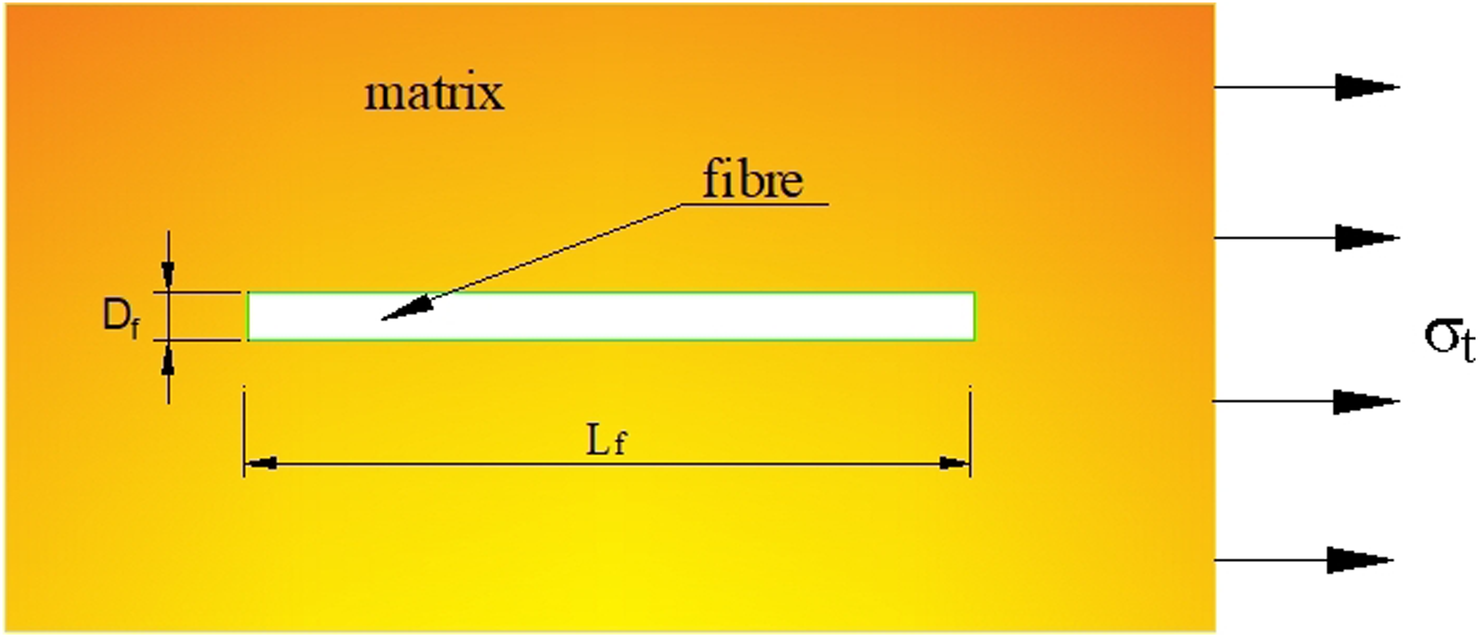
Conclusions
In the study, the two-phase summing principle of composite was fundamentally adopted, as well as extending the application range of the Mohr–Coulomb strength criterion. In the light of the numerical modelling software Flac3D, the uniaxial tensile computing model of a cylindrical polymer specimen with equal diameter and height containing the randomly distributed chopped basalt fibres as the reinforcement and the thermosetting epoxy resin with higher cohesiveness and fluidity before curing as the matrix was established. Afterwards, the numerical simulation was implemented from the two aspects between the number and the distribution angles of discrete fibres in the finite volume of the model. In the meantime, the variation rules and the induced intrinsic mechanism of the axial tensile properties of the specimen in the initial and ultimate tensile states under the static load and normal temperature and pressure were investigated and summarized, and the variation characteristics of the stress–strain curve of basalt fibre thermosetting resin matrix composites were attained. The results have manifested that: (1) The uniaxial tensile deformation process of the cylindrical solid polymer specimen containing fibres within the limit scope can be reflected by the stress–strain curve at any points along the axial direction under different constant loading rates, which will usually undergo the stages of linear elasticity, yield, strain softening, smooth flow and strain hardening before failure; (2) In terms of the pure cylindrical curing systems of epoxy resin with original weaker strength and stiffness, the quantitative addition of discrete basalt fibres can enhance its axial tensile strength in a limited amplitude, which is due to the function of sustaining more tensile stresses and playing a strengthening role of fibres; (3) With regard to the standard cylindrical polymer specimen, the addition of random discontinuous fibres should be controlled within a reasonable range, because an increase in the number of fibres within the finite volume will decrease the dispersion level of the reinforcing fibres among the resin matrix and exacerbate the expansion of internal void structures or other detrimental factors, thereby impeding the enhancement of tensile properties of composites. (4) When the number of fibres within a specific volume range remains constant, if the distribution directions of disperse fibres in the standard cylindrical polymer specimen are kept parallel to or collinear with the axial direction of the specimen and the direction of load application to the maximum, the dissipation and loss during the transferring phrase of tensile stresses transfer can be decreased, and the utility ratio of composite tensile strength can be significantly improved.
Whence, the aforementioned analysis findings can lay a theoretical foundation for the subsequent study of the effects of fibre length on the comprehensive properties of circular cross-section specimens by virtue of the methods of the mechanical analysis, the numerical test and the field test, and contribute to promote the research and development of high-performance basalt fibre reinforced composite products with various forms in engineering practice.
Future scope
Although the preliminary analyses have been conducted and the demonstration outcomes have been presented regarding the influence laws of various fibre number and distribution angles on the integral axial tensile properties of a cylindrical polymer specimen in this study, the substantial scope remains for investigating the effects of the fibre length, the fibre diameter, the fibre braided shapes and other parameters on the comprehensive properties of the circular cross-section specimen through the mechanical analyses, the numerical simulations and field investigations. By virtue of modifying the cross-sectional shape of circular specimens, such as transitioning to the ribbed section, the obtained theoretical results are directly applied to the engineering practice so that these advancements can be extended to the development of innovative material supporting structures within the domain of geotechnical engineering, enhancing the shear deformation capabilities of supporting systems to accommodate the large deformation of surrounding rock and soil mass, thereby ensuring the safety and stability of underground space supporting structures, whose aspect merits further exploration and discussion.
Footnotes
Acknowledgments
The authors gratefully acknowledge the precious support for this research from the National Natural Science Foundation of China (Grant No.51874112), and the State Key Laboratory Open Funding Project of Mining∼Induced Response and Disaster Prevention and Control in Deep Coal Mines (Anhui University of Science and Technology) (Grant No.SKLMRDPC22KF02), and the University Natural Sciences Research Project of Anhui Province (Grant No.2022AH051805).
Author Contributions
Conceptualization, H.L. and H.Y.; Funding acquisition, H.Y. and J.H.; Writing-original draft, H.L.; Writing-review & editing, H.L., H.Y., X.Z., J.H., Y.Z., L.P., Z.G. All authors have read and agreed to the published version of the manuscript.
Declaration of conflicting interests
The author(s) declared no potential conflicts of interest with respect to the research, authorship, and/or publication of this article.
Funding
The author(s) disclosed receipt of the following financial support for the research, authorship, and/or publication of this article: This work was supported by the National Natural Science Foundation of China (Grant No.51874112), and the State Key Laboratory Open Funding Project of Mining∼Induced Response and Disaster Prevention and Control in Deep Coal Mines (Anhui University of Science and Technology) (Grant No.SKLMRDPC22KF02), and the University Natural Sciences Research Project of Anhui Province (Grant No.2022AH051805).
Data availability statement
Data are contained within the article.