
Abstract
A low-cost, low-waste manufacturing method for advanced thermoset composite parts could improve market penetration of composites compared to other engineering materials such as aluminum or steel. Such a method could combine some of the new trends in composites manufacturing such as resin infusion (eliminates need for prepreg), out-of-autoclave consolidation, and snap curing. The feasibility of a hybrid process with these characteristics has been demonstrated by uniting liquid composite molding, resin curing by electron beam irradiation, and high pressure consolidation with specialized elastomeric tooling. To demonstrate feasibility, a mold set was designed to make flat, square four-ply woven carbon fiber parts by (1) vacuum-infusing dry preforms with an electron beam–curable epoxy resin in minutes, (2) applying 690 kPa of uniform pressure and consolidating in seconds using an elastomer-faced specialized elastomeric tooling tool and simple hydraulic press, and (3) curing in seconds using a 3 MeV electron beam source. To better understand how various process parameters affect part performance, parameters are varied in a simple design of experiments, and flexural strength and stiffness, thickness distribution, fiber and void volume fractions, surface roughness, and cross-sectional characteristics (via microscopy) are measured and compared.
Introduction
A potentially rapid, low-cost, and low-waste process for manufacturing advanced thermoset composite parts might involve (1) resin and reinforcement provided unmixed and dry, respectively, to avoid the added expense and storage requirements of “prepreg”; (2) uniform high consolidation pressure applied to the laminate or sandwich structure part without using autoclave; and (3) resin matrix cured rapidly without using heat. Such a process would allow manufacturers to store dry fiber and unmixed resin nearly indefinitely, combine the materials and consolidate them, and then snap-cure the resin to form a high-quality, high-performance part. Existing advanced composite manufacturing methods possess these characteristics either individually or in combination to some degree, but they have not been fully integrated together until now.
This article presents a feasibility study involving a completely new tooling design concept and set of processes that combines resin infusion (RI) to eliminate the need for prepreg materials, specialized elastomeric tooling (SET) without a heated mold as an energy-efficient and low-cost alternative to autoclaving, and electron beam (EB) irradiation with an appropriate resin system to significantly reduce cure time. For convenience sake, the new hybrid process will be referred to as EB-SETRI. Although these individual processes have been demonstrated commercially (some for decades), the novelty of the combined process is in the tooling design and how the processes are integrated.
Background
The need for prepreg material, including the high cost of material and storage requirements (e.g. freezer), is eliminated by using RI induced by vacuum, as shown in Figure 1(a). 1 Dry reinforcement that is frequently combined with cores or other special inserts (constituting the “preform”) is placed on a rigid tool. The part surface in contact with the mold is called the “A-side” surface. The preform is usually covered with a peel ply, perforated release film, and a flexible polymeric sheet or reusable bag (e.g. silicone rubber) sealed around the tool perimeter to provide compression on the non-tool or “B-side” surface. Vacuum applied between the tool and sheet/bag draws in low-viscosity (<1000 cP) thermosetting resin and completely impregnates the slightly compressed reinforcement preform. Finally, vacuum is released and the sheet/bag is removed once the part has cured. 2 RI offers a number of important advantages over traditional hand layup including higher production rates, better repeatability, ease of automation (especially by using preforms), unlimited setup time, less wasted resin, and reduced worker exposure to airborne pollutants such as styrene and other volatile organic compounds.
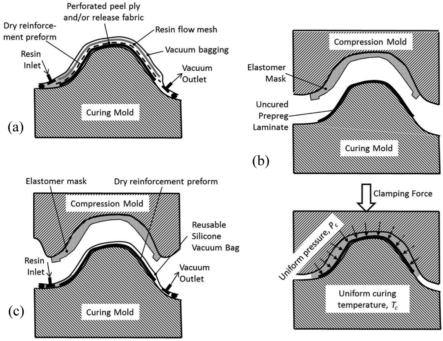
Schematics of the (a) RI, (b) SET, and (c) SETRI processes.
When higher fiber volume fractions (Vf) are required for high-performance applications such as aerospace, vacuum-bagged parts are typically consolidated and cured under high pressure and temperature in an autoclave, which is considered by many to be one of the most significant bottlenecks in composites manufacturing. 3 To achieve similar Vf levels (55%–65%) by RI, high resin injection pressures (0.5–0.7 MPa) and even higher post-infusion pressures (1.4–2.0 MPa) in a process called resin transfer molding (RTM) are used to adequately wet-out the preforms. High pressure RTM (HPRTM) equipment capable of post-infusion pressures up to 10 MPa is also available. 4 A RTM variant called compression RTM (CRTM), which has been around for nearly two decades, involves preplacing a fiber preform in a mold (similar to RTM), injecting liquid resin while the mold maintains a large gap for ease of resin flow and wet-out, closing the mold to achieve complete through-thickness wet-out and high laminate consolidation (similar to compression molding), and allowing the workpiece to cure in place within the heated mold set.5,6 However, RTM and HPRTM require high pressure resin injection equipment, and both RTM and CRTM need highly engineered, expensive, and leak-proof molds to work properly. 7 Another interesting process developed over a decade ago is resin infusion between double flexible tooling (RIDFT). 8 This process involves vacuum infusion processing of a flat stack of dry reinforcement sandwiched between two diaphragms with resin, which is followed by a double diaphragm forming step (similar to work by Gutowski et al. 9 ) over a rigid tool and finally in-place curing. However, RIDFT does not provide high consolidation pressure nor an A-side surface in direct contact with the rigid mold.
High consolidation pressure and curing temperature can also be achieved without an autoclave using the patented SET process. 10 SET (see Figure 1(b)) involves placing an uncured laminate or sandwich workpiece consisting of prepreg material onto a temperature-controlled, metal or composite curing mold. The part is then clamped between the curing mold and a matching rubber-coated compression mold that is engineered to provide uniform pressure (at the curing temperature) when a specific clamping force is applied. SET was first demonstrated by Walczyk et al. 11 for a simple 2-D axisymmetric composite part, and, more recently, has been shown to work for complex carbon-epoxy 3-D laminate parts12,13 and thermoplastic parts. 14 Benefits of SET compared to autoclaving and out-of-autoclave (OOA) processes, such as Quickstep 15 and RapidClave, 16 include order-of-magnitude reductions in preparation time, energy used, consumable costs, and waste, but with no adverse effect to part quality. SET also uses less complex, more flexible tooling in comparison to CRTM—this allows the use of other resin cure chemistries, such as electron beam processing. Even with its many advantages, SET poses a few challenges. Properties of the elastomeric mask have been shown to degrade slightly over many production cycles due to fatigue, 17 and the effects of other curing methods (e.g. electron beam) are not known. SET also requires both a rigid tool for the A-side and a relatively complex compression tool and elastomer for the B-side, whereas Quickstep, RapidClave, and vacuum-bagging followed by autoclaving only require the former. Despite these issues, SET has been commercialized and is currently used in production. 18
Current thermosetting resin cure mechanisms in roughly descending order of cure speed and ascending order of energy efficiency are thermal, X-ray, ultraviolet (UV), and electron beam (EB). Thermal cure resins, the most prevalent mechanism for thermoset composites today, 19 must be heated up to initiate crosslinking thereby creating a solid polymer matrix. Although most thermal cure resins take 10’s of minutes or hours to fully cure, some recent chemistries can be cured as quickly as 90 s, 20 but thermal management of the tool and resin injection procedures can be quite challenging. Curing with X-ray irradiation works for thick parts (300–600 mm) and allows simultaneous curing through the part thickness, although cure times are always longer than EB due to lower dose rates.19,21,22 Compared to EB resins, UV systems (formulated with a photoinitiator) are generally higher cost as a result of the additional photoinitiator(s) and also slightly less energy-efficient. 18 Unfortunately, depth of penetration depends on degree of transparency, and they cannot cure in the presence of inherently opaque carbon fibers. EB curing systems are broken up into two major categories, cationic and free-radical, 23 each with its own advantages and disadvantages. These systems are typically more energy-efficient than thermal systems (up to 60% according to Chmielewski and Al-Sheikhly 24 ) and cure in seconds to 10’s of seconds depending on beam energy level, formulation, and scan speed.
Electron beam curing of composites, the chosen method for this study, has been used since the early 1970s, with some research occurring in the 1990s and early 2000s. 19 Many studies have shown the benefits of an EB-cure system for composites as compared to traditional thermal cure including lower energy consumption; faster processing; reduced health, safety, and environmental costs; and reduced materials handling issues.25–27 In addition, EB-cure epoxies have been shown to have similar properties to high-performance thermosetting epoxies.27,28 In fact, due to lower temperature processing, the resulting thermal stresses can be very low. 29 While some research has shown poor interlaminar shear strength, this is likely the result of incompatible fibers for the resin; for example, modifying the chemistry of the fiber/resin interface has been shown to increase shear strength by 30%–50%. 30 Other major issues hindering adoption of EB composite processing are the high capital cost of a high-energy electron beam equipment (1–10 MeV), processing difficulty, and poor part quality when lower power electron beam systems are used. 19 Despite the high capital costs, the per part costs of EB-cured composites have been shown to be very low, resulting in large cost reductions per part (between 10% and 65%) depending on the size, complexity, and quantity of parts produced.21,28
While there may be safety concerns by those unfamiliar with EB processing, it is a proven technology that has been in use for over 30 years, particularly in the medical and wire/cable industries. The process uses an electric-powered irradiation source—this means that there are no chemical residues, no isotopes handled in any way, no radioactive isotopes created, and no residual radiation persists when the power is shut off. The major concern with high-energy electron beams is how to contain the radiation that is produced while in operation. The electron beam from a 3 MeV system, for example, will not penetrate more than 6.4 mm into most metals, so this is less of a concern. The bigger issue is that the process also produces X-rays, so a 3 m thick concrete shield is required to prevent radiation from leaving the processing chamber. Other important safety features of commercial high-energy EB systems include controlled access, fail safe systems, automatic power-down sensors, and radiation and ozone level monitoring. When all these precautions are taken into consideration, electron beam irradiation can be a fast, inexpensive process for high production volume applications.
Tooling design
To test feasibility of EB-SETRI, a simple 4-ply × 152 mm × 152 mm flat composite part consisting of 12 K plain weave carbon fiber cloth with an areal density of 0.065 g/cm2 (Fibre Glast #3221, Brookville, OH, USA) and a [0]4 layup was chosen along with two EB resin systems—RCT 2005-102-1 (cationic) and RCT 2005-102-2 (free-radical) from Rapid Cure Technologies (East Syracuse, NY, USA). According to the manufacturer, the cationic curing resin has a 250–300 cP viscosity range at 25 °C (within typical range for infusion resins) and requires 40–80 kGy (kilogray) of EB irradiation to fully cure (with an optional heat post-curing step). The free-radical curing resin has a 1000–1300 cP viscosity range at 25 °C and requires 30–60 kGy. The literature (e.g. Pearce et al. 31 ) suggests that the viscosity range of the free-radical resin is at the upper limit of what should be considered for RI, so that the resin may not fully permeate the fiber preform in a timely manner. Initial experiments showed that cationic resin infused relatively quickly and the free-radical resin fully infused the preform within the time constraints. Following wet-out, the laminate is consolidated using a uniformly applied pressure of 0.69 MPa (typical level for high-performance, autoclaved aerospace parts).
The combination of RI, SET consolidation, and EB irradiation curing imposes specific requirements on the tooling design in that it must
Maintain a specified force on the composite part after RI, which results in a uniform pressure level over the entire part surface during consolidation from the SET tooling;
Allow for RI and complete wet-out of the dry fiber preform by pulling vacuum only;
Not attenuate the EB energy level significantly to prevent full curing; and
Be rigid enough to maintain shape tolerances.
The resulting EB-SETRI mold design, shown in Figure 2, consists of
An aluminum top mold CNC machined with a ball endmill to accommodate the SET-designed mask geometry and bolt holes around the perimeter to maintain compression using an threaded bolt/nut connection;
A specially designed elastomeric mask that mates with the top mold and applies uniform pressure on the composite panel when compressed with a specific clamping force;
A compression sponge used to maintain a low force on the gasket portion of the elastomeric mask for vacuum sealing;
An aluminum spacer with resin inlet and vacuum outlet ports along with edge plenums along the entire part width to allow uniform RI; and
A sufficiently stiff composite sandwich structure for the bottom mold that seals around the infusion area and provides an unobstructed curing window with minimal EB attenuation.
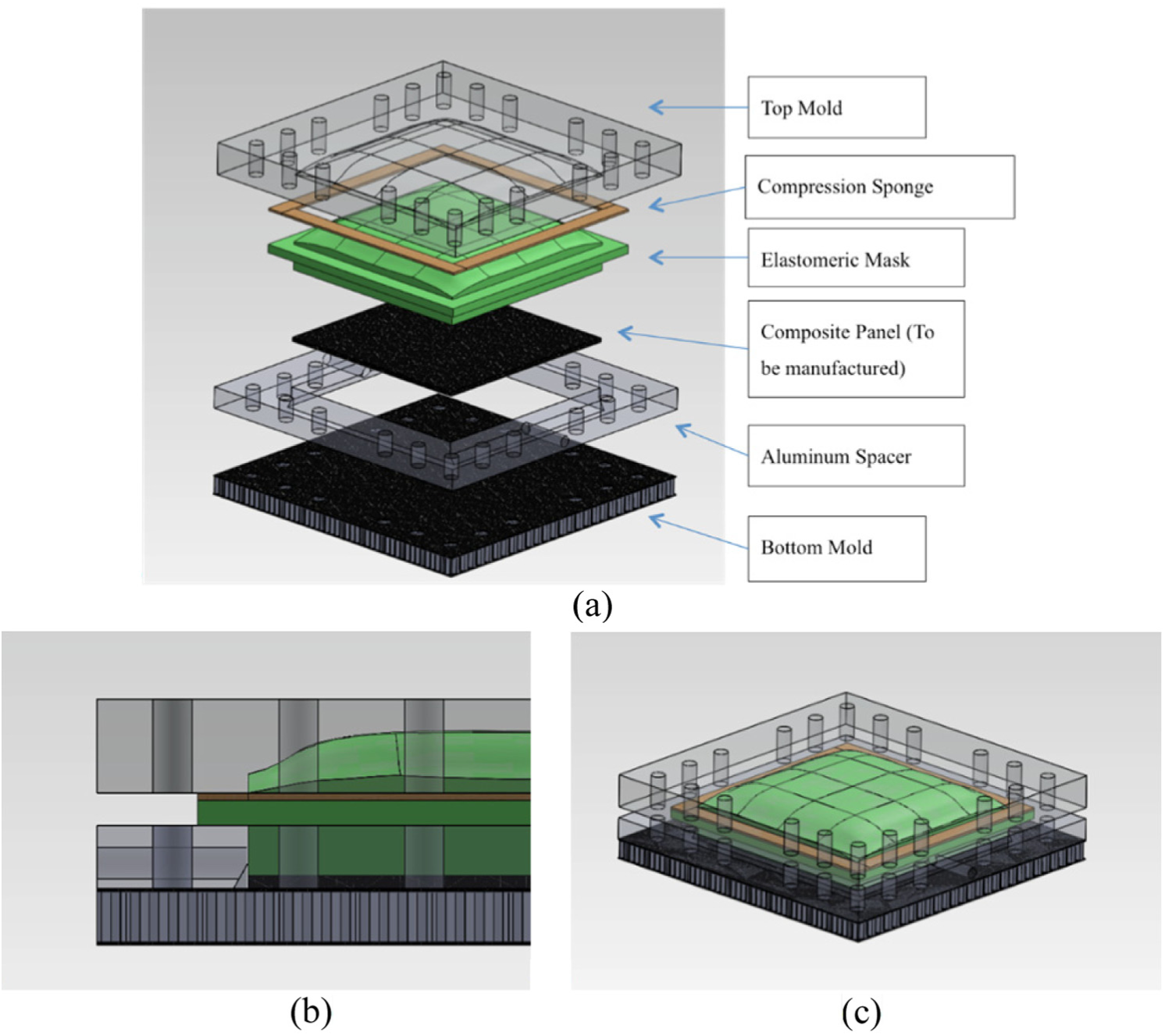
(a) Exploded view of the EB-SETRI tooling components, (b) cross-sectional view, and (c) assembled mold set with the top mold and aluminum spacer shown as semi-transparent.
Specifics on how each requirement was addressed are discussed in the following discussion.
A SET elastomer mask shape made of a tin-cured silicone rubber (Smooth-On Mold Max® 40) was designed to provide a uniform 0.690 MPa pressure over the entire part surface using a proprietary algorithm and structural modeling with Abaqus finite element analysis (FEA) (see Walczyk and Kuppers 12 for more information). The pressure distribution plot based on FEA simulation for the first iteration with a constant thickness mask (Figure 3—left) shows how non-uniform the resulting pressure is. However, the fourth and final iteration resulted in the variable-thickness mask (Figure 2) with a more uniform pressure distribution, as shown in Figure 3—right. To hold the specified force during EB exposure and curing, the bottom mold was designed with a series of bolt holes uniformly spaced around the perimeter. As the mold is compressed in a hydraulic press to the set load, the perimeter bolts are tightened just enough to maintain the correct level of compression during curing when press load is finally released.
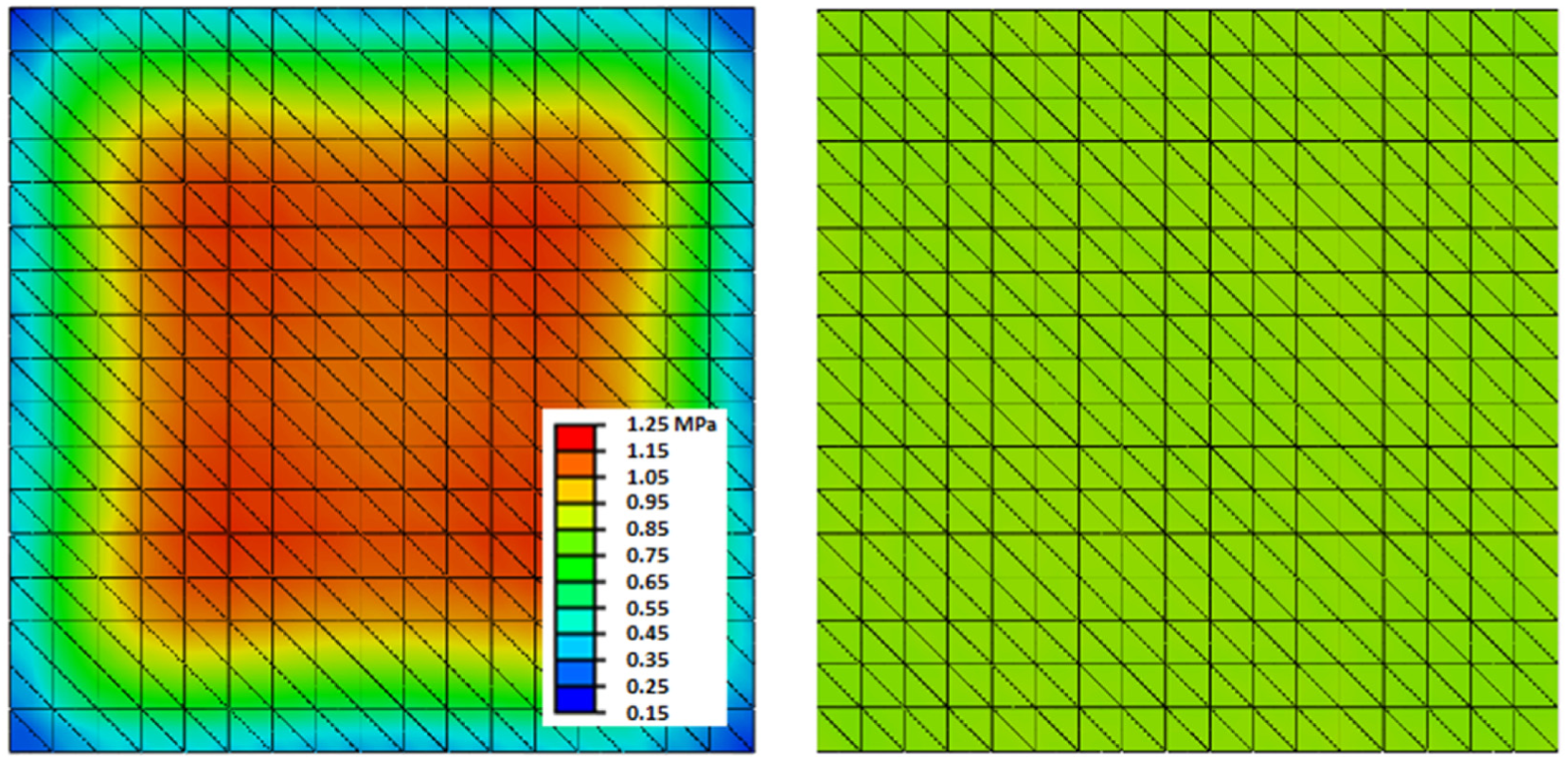
Colored pressure plots of first SET mask design iteration, that is, uniform thickness mask (left) and the variable-thickness fourth and final iteration (right) using Abaqus Finite Element software and a proprietary algorithm.
To reduce issues involved with a centrally located inlet or outlet (e.g. compressing in a hydraulic press, EB penetration through the port), the ports were placed on either side of the square laminate mold. An acrylic mold was constructed to visually monitor the infusion process (see Figure 4) before cutting the metal. Several infusion tests were completed to identify any issues that would be seen in part production. The tests were conducted using the carbon fiber cloth preform and fluorescent-dyed corn syrup as a resin analog (due to similar viscosity range as EB resins).
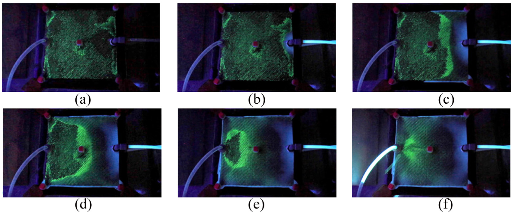
Sequence (a–f) of resin flow experiments.
This configuration is easy to implement on EB-SETRI tooling that must initially be pressed on the top and bottom and needs an unobstructed window during EB irradiation after tightening the bolts. Fill behavior of the fluorescent ink-dyed resin analog was tested, and the progression of the resin analog infusion for this configuration is shown in Figure 4(a)–(f). Flow in the figure can be seen race-tracking along the edges of the mold from right to left if preform dimensions are not tight enough to completely fill the mold cavity. The resulting flow pattern created a void area around the vacuum port that could only be filled by allowing additional resin to flow through the outlet port which, unfortunately, is wasted material. Although outside the scope of this research, RI porting and flow control can be optimized to provide rapid and complete preform wet-out using Computational Fluid Dynamics (CFD) modeling (e.g. LIMS from the University of Delaware, Newark, DE, USA).
EB penetration simulations were performed using CASINO (monte CArlo SImulation of electroN trajectory in sOlids) software. 32 CASINO uses Monte Carlo simulation to generate electron trajectories through solids of user-defined density and thickness. Initial simulations showed that the 3.0 MeV EB source used for initial irradiation experiments would not supply sufficient energy level and dose to the composite part through any aluminum or steel tool structure more than 6.4 mm thick in between the source and the part. As a result, other stiff structures more transparent to EB irradiation were investigated, specifically a composite sandwich construction. A commercially available polypropylene honeycomb core/carbon-epoxy sandwich structure (Dragonplate® from Allred and Associates Inc., Elbridge, NY, USA—a 13 mm-thick sandwich structure with PP honeycomb core and 0.8 mm thick quasi-isotropic carbon fiber skins) was chosen for the curing mold to provide a combination of sufficient strength, stiffness (discussed later), and low EB attenuation. CASINO Simulation of the Dragonplate (Figure 5) showed that a minimum 2.0 MeV beam strength was required for sufficient penetration to cure the resin.
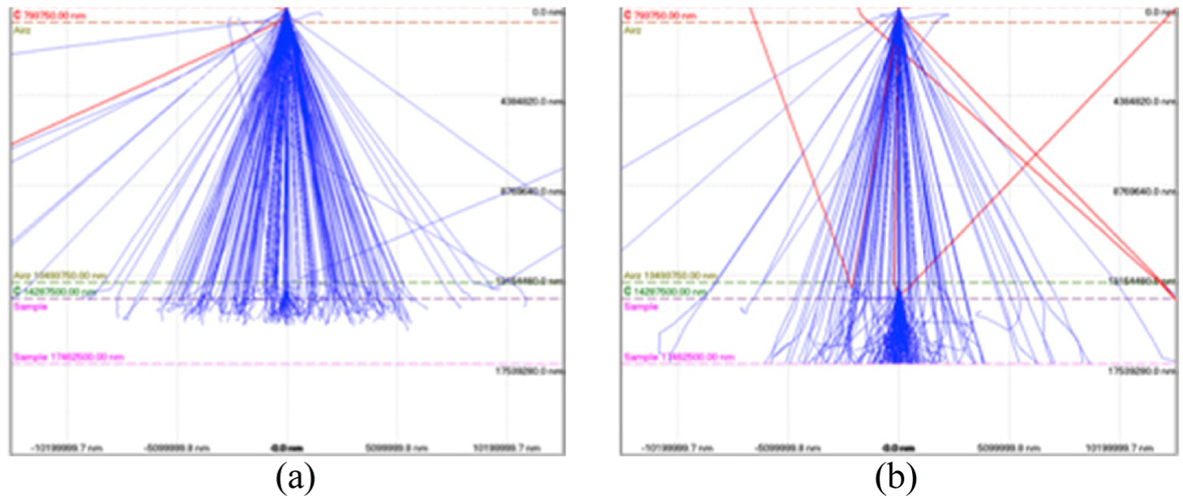
(a) 1.0 MeV Monte Carlo Simulation and (b) 2.0 MeV Monte Carlo Simulation.
The composite sandwich structure used as the bottom mold was structurally modeled using FEA (Abaqus) to predict maximum deflection when subjected to the 0.690 MPa pressure over a 152 × 152 mm square area. Results of this model predicted a maximum center deflection of 0.1 mm (0.004″), as shown in Figure 6. The Dragonplate material was deemed sufficiently stiff by the industrial collaborators for this feasibility study, although maximum allowable part deflection during processing of a real part would be set by the customer.
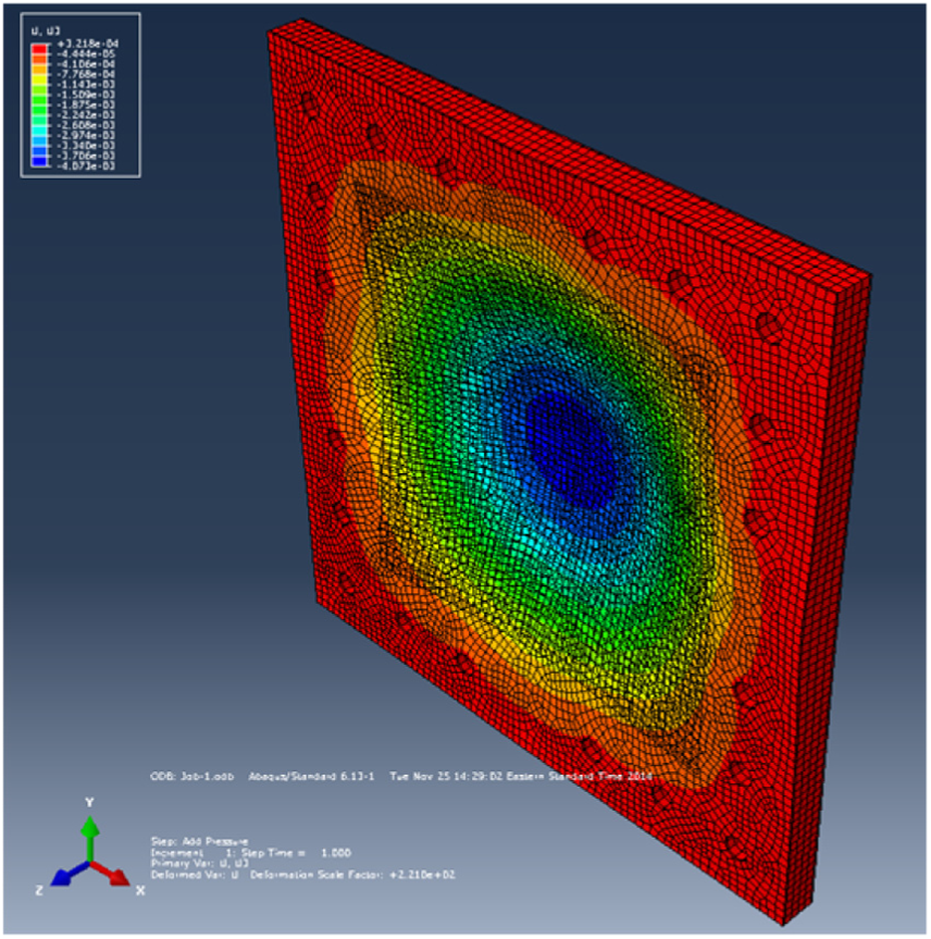
FEA model of bottom mold honeycomb sandwich structure.
Experimental setup and design
The experimental setup and design are discussed in this section. Referring to Figure 2, the complete process for making a composite part by EB-SETRI includes the following steps:
Assemble the bottom mold and spacer;
Hand layup four plies of carbon fiber cloth (i.e. preform) cut to size in the bottom mold cavity; place the elastomer mask, compression sponge, and top mold over it; and assemble 14 compression bolts, but do not tighten;
Vacuum infuse the preform with resin;
Apply the required compression load to the mold using a hydraulic press with force readout and tighten bolts to just maintain this level of compression;
Clamp the resin and vacuum tubing and place onto the EB source conveyor;
Expose mold set and part to the required EB energy level and dose;
Remove mold set and part from the conveyor and disassemble the mold; and
Remove the cured composite part and clean any residue off the mold surfaces.
RI was accomplished by running plastic tubing from the resin pot to the mold inlet port then from the mold outlet through a resin trap to a Marathon Electric 0.37 kW oil-free high vacuum pump (see Figure 7). A maximum gauge vacuum level of 91 kPa was maintained during infusion for all specimens, and complete infusion was reached after about 3 min. Following infusion, a 20 ton Sunex hydraulic shop press with a ∅5.0 cm cylindrical ram was used to apply the required force to the mold and allow the clamping bolts to be tightened.
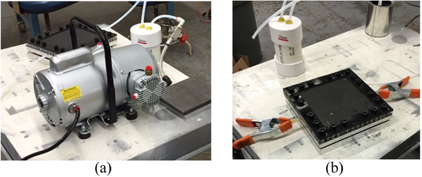
(a) Vacuum infusion process setup and (b) EB-SETRI mold set after infusion with hoses clamped.
A 3 MeV Dynamitron EB accelerator (IBA Industrial, Edgewood, NY, USA) with a 2.5 cm × 91 cm beam window (Figure 8(a) and (b)) was used to cure the composite part compressed within the mold set. The EB accelerator has a conveyor system with coordinated velocity (Figure 8(c)) to provide a consistent radiation dose to the workpiece. During processing, the bottom mold was facing upward toward the accelerator (see Figure 7(b)). Per the resin manufacturer’s recommendation, the cationic resin required four 20 kGy passes for a total of 80 kGy while the free-radical resin required four 10 kGy passes for a total of 40 kGy. Total exposure time per part was approximately 30–40 s. It should be noted that only 1/6th of the accelerator’s beam window was used for actual part curing, so six mold sets across or a part 6 times longer could have been irradiated simultaneously.
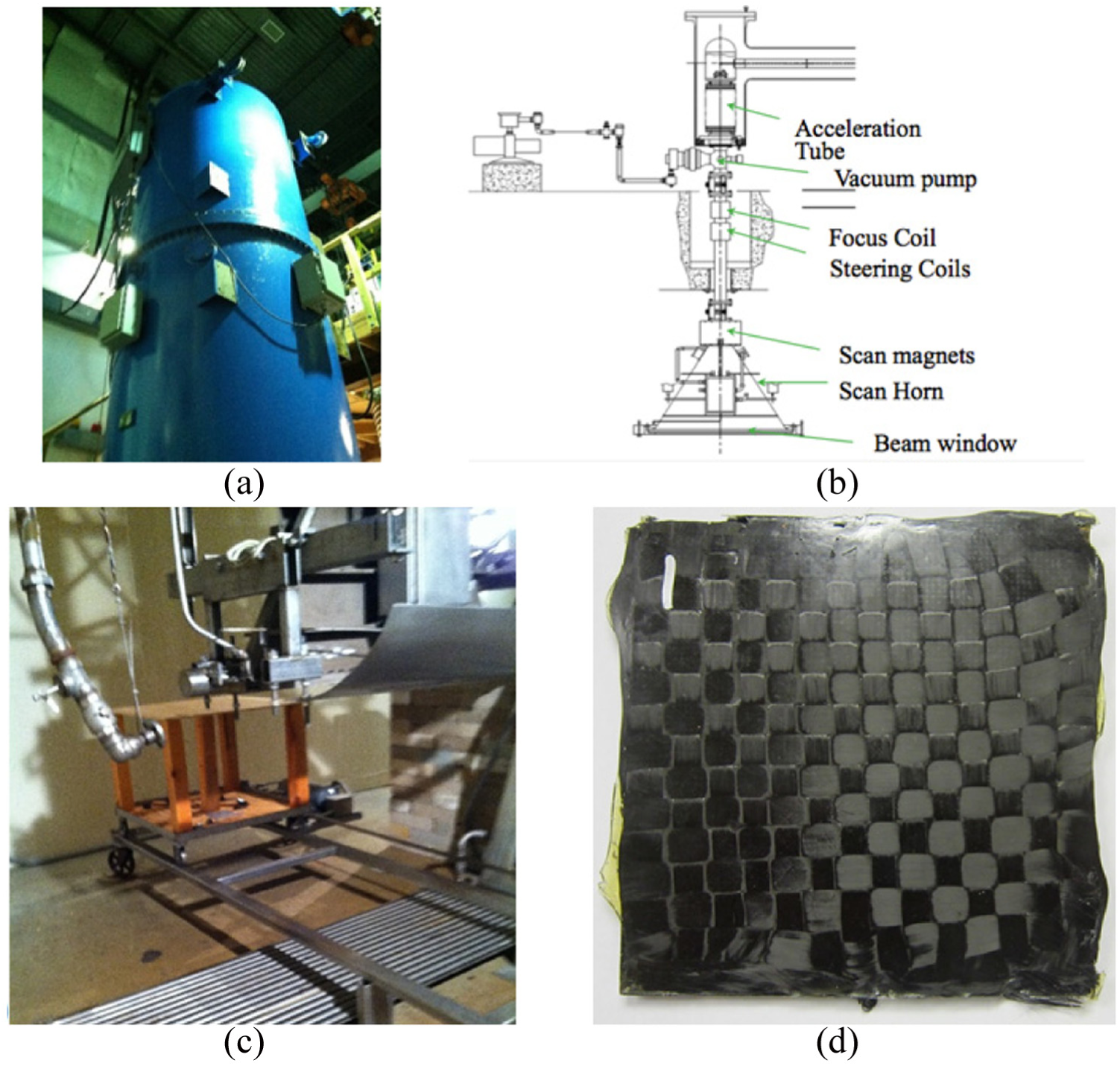
(a) 3 MeV EB accelerator, (b) schematic of accelerator, (c) conveyor system for irradiated samples, and (d) example of a flat composite part.
As previously stated, the main research objective was to demonstrate EB-SETRI process feasibility and identify specific manufacturing issues that should be investigated to demonstrate manufacturing viability for eventual scale-up and part production. Hence, laminate parts were made with only one process variable, that is, consolidation pressure, at two pressure levels—slightly below atmospheric (0.091 MPa) to mimic vacuum RI alone and high pressure (0.690 MPa). Laminates processed at the higher pressure were expected to be both thinner and have higher specific flexural strength and stiffness. It should be noted that EB-cured parts have not been produced using other composites manufacturing processes that provide high consolidation pressure (e.g. RTM, autoclaving), to date, primarily because of tooling interference, logistical, and beam attenuation issues. This is the main reason why the SET process was chosen.
Because of limited time available on the EB accelerator (due to a $1000/h rate), only three replicate parts (see example in Figure 8(d)) were made for each combination of pressure (two levels) and resin (cationic and free-radical) for a total of 12 vacuum infused and cured parts. In addition, two additional parts (13 and 14) were made by laying the individual fiber plies in the mold wet (i.e. pre-impregnated with resin) for each resin to imitate complete RI. All parts were tested and their characteristics are shown in Table 1. It should be noted that comparing results from characterization of these parts made by EB-SETRI to other more established processes is not valid, since the difference in resins effectively render the comparison meaningless.
Specimens fabricated and experimentally tested.
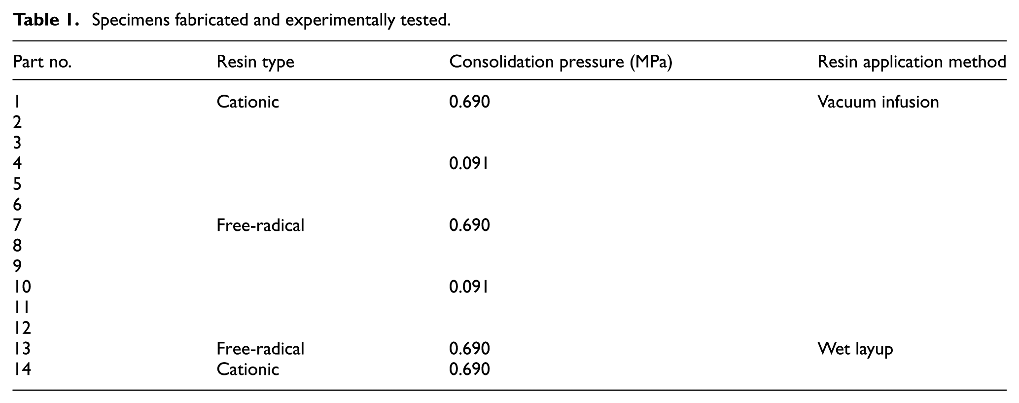
Part quality metrics measured for the parts listed in Table 1 include part thickness distribution, average surface roughness, flexural strength and secant modulus, and fiber and void volume fractions.
Part thickness, t, was measured at 16 locations (equispaced 4 × 4 grid with 5 cm spacing) on each part using an electronic C-frame thickness gauge with flat and ball anvil faces.
Average surface roughness, Ra, is also an important quality metric, especially for composite parts used in aerospace and recreational products. Ra values were measured at two random locations on both the A- and B-sides of the parts using a ZETA-20 optical profiler.
Flexural strength, Sf, and secant modulus,
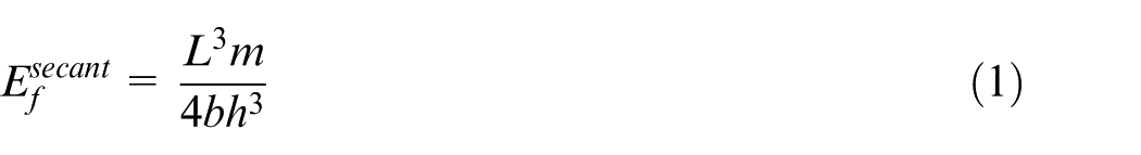
where L = support span, m = slope of the secant of the force-deflection curve, b = width of beam, and h = thickness of the beam. The maximum tensile stress in flexure located at the lower outer surface at beam midspan is found using
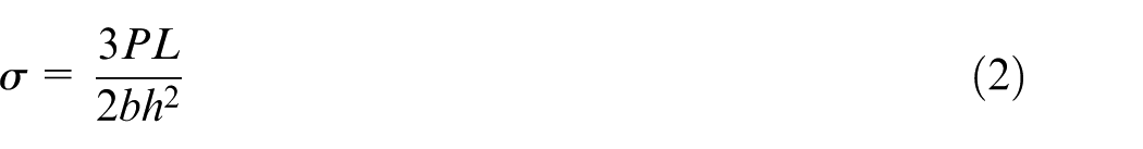
where P = load applied by the Instron Microtester. The flexural strength is simply the maximum stress level reached during 3-point bend testing.
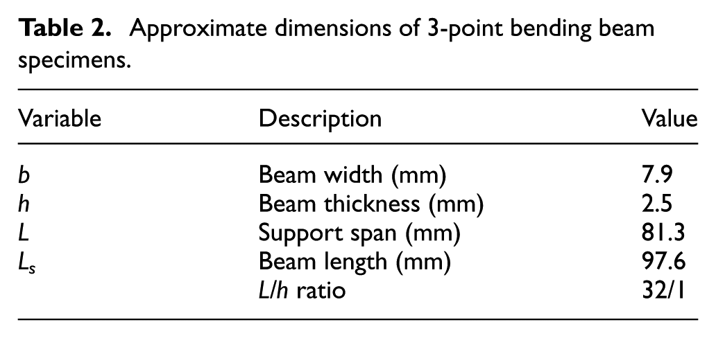
Approximate dimensions of 3-point bending beam specimens.
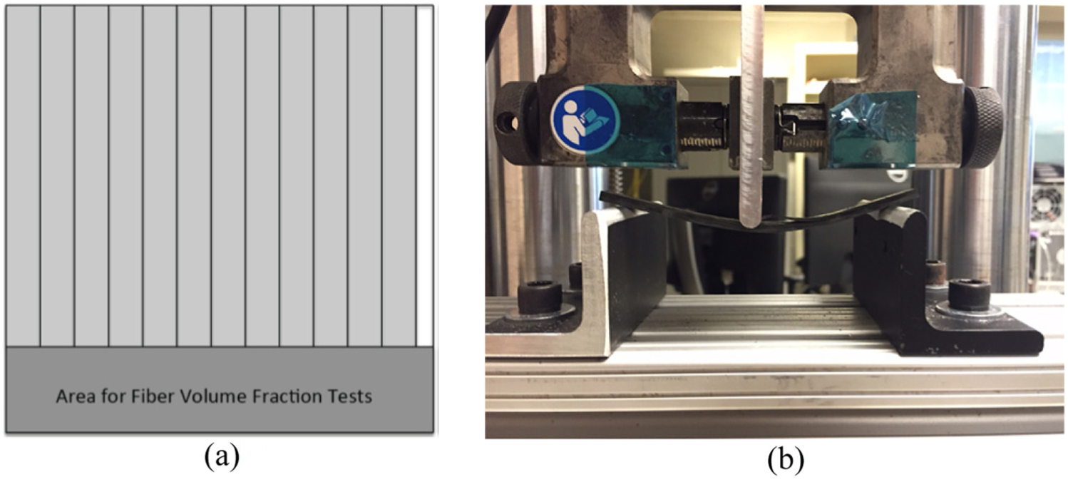
(a) Schematic showing how flat composite parts were sectioned for 3-point bending and fiber/void volume fraction tests and (b) picture of experimental setup used to measure Sf and
Fiber volume fraction, Vf, and void volume fraction, Vv, were measured for 25 mm square specimens sent out to an independent testing laboratory (Cincinnati Testing Laboratories, Cincinnati, OH) using the chemical digestion method (ASTM D3171). For these tests, the authors chose to send three samples from the stiffest (i.e. highest flexural secant modulus) specimen in each combination of resin type and pressure level.
Experimental results and discussion
As expected, thickness decreases significantly when resin-infused samples are uniformly compressed with 0.690 MPa of pressure (see Table 3). Specifically, thickness reductions, on average, were 39% for the cationic resin parts and 25% for the free-radical resin parts. A decrease in thickness without adversely affecting strength or stiffness also corresponds to “lightweighting” of the part, which is desirable for many product applications where energy conservation is critical (e.g. aerospace).
Thickness and surface roughness measurement results.
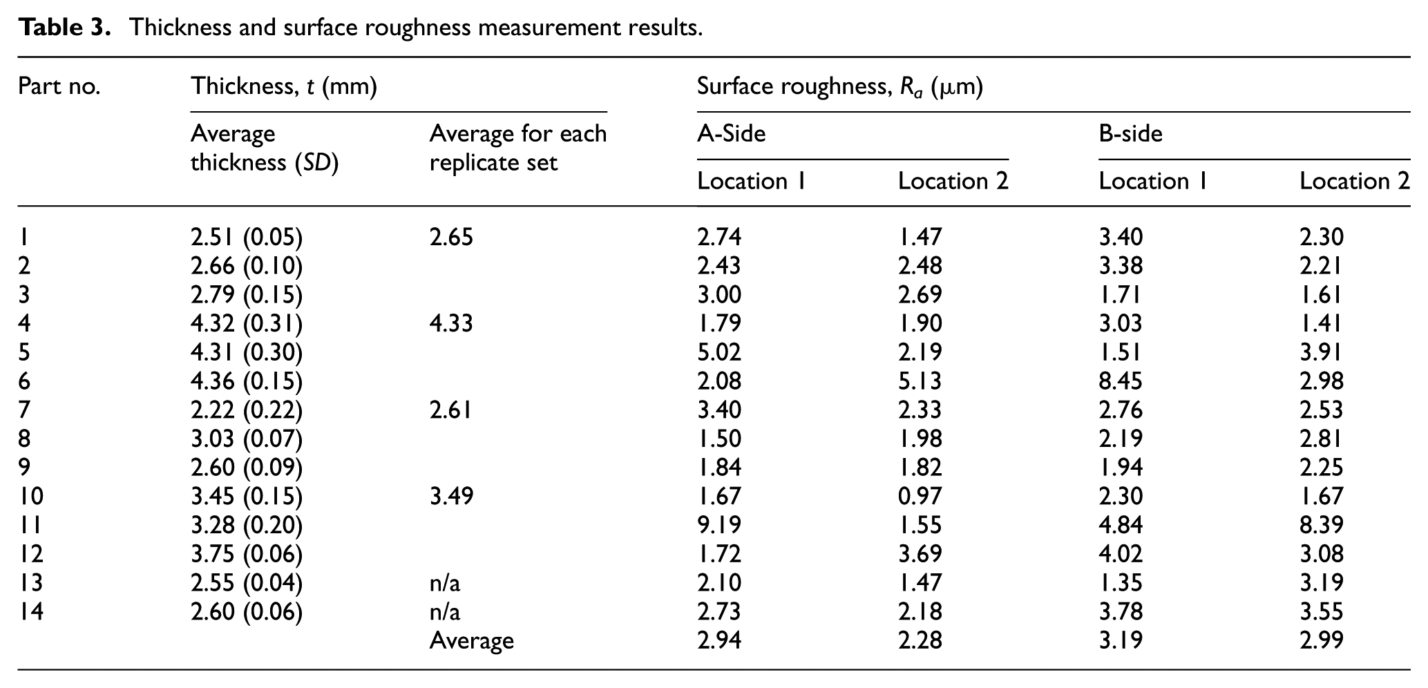
The average measured surface roughness of the B-side is only 18% higher than the A-side (also see Table 3). This result is surprising when considering the significant differences in surface roughness between the A- and B-sides for carbon/epoxy parts made with “prepreg” material consolidated/cured using autoclaving and SET (nearly two orders-of-magnitude rougher according to Walczyk and Kuppers 12 ).
Qualitative assessments of fiber preform wet-out for each part are provided in Table 4. Note that “small” voids are considered less than 1 mm in size, “medium” between 1 and 4 mm, and “large” greater than 4 mm. During testing, it became apparent that while RI can certainly be a viable process capable of producing quality parts, it was very inconsistent for the flat, square mold design and type of reinforcement chosen. The wide, thick weave made infusion difficult resulting in defects such as dry areas near the fiber interfaces. Fiber preform wet-out was generally poor with just vacuum but improved when high pressure was applied, since resin was forced into dry spots. It also appeared that the free-radical resin bonds to the elastomeric mask causing surface damage after only 7–10 part infusions.
Experimental observations and data.
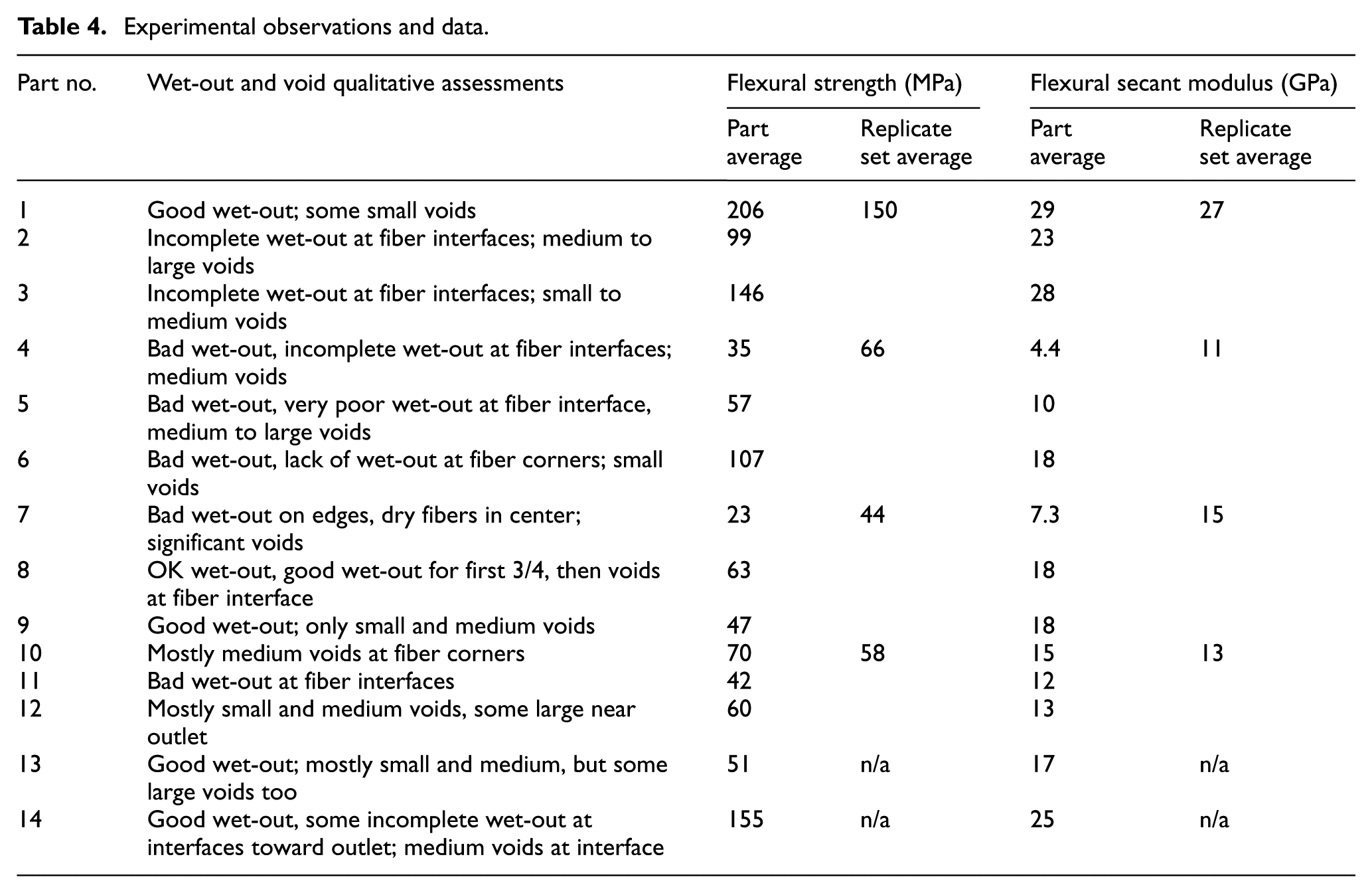
Mechanical properties vary with the degree of reinforcement preform wet-out, consolidation pressure, and resin (Table 5). Wet-out varied significantly from parts with nearly complete infusion (e.g. Specimens 1, 9, 13, and 14) to those with dry spots (Specimens 4–7 and 11). As seen in Table 4, the cationic resin with high consolidation pressure provided higher flexural strength and flexural secant modulus as compared to all free-radical resin specimens and those made using low consolidation pressure. This applies to both vacuum infusion and wet layup resin application methods. Interestingly, there is essentially no difference in flexural strength or modulus between the resin-infused parts (Nos. 1, 2, and 3) and wet layup part (No. 14) made with the cationic resin.
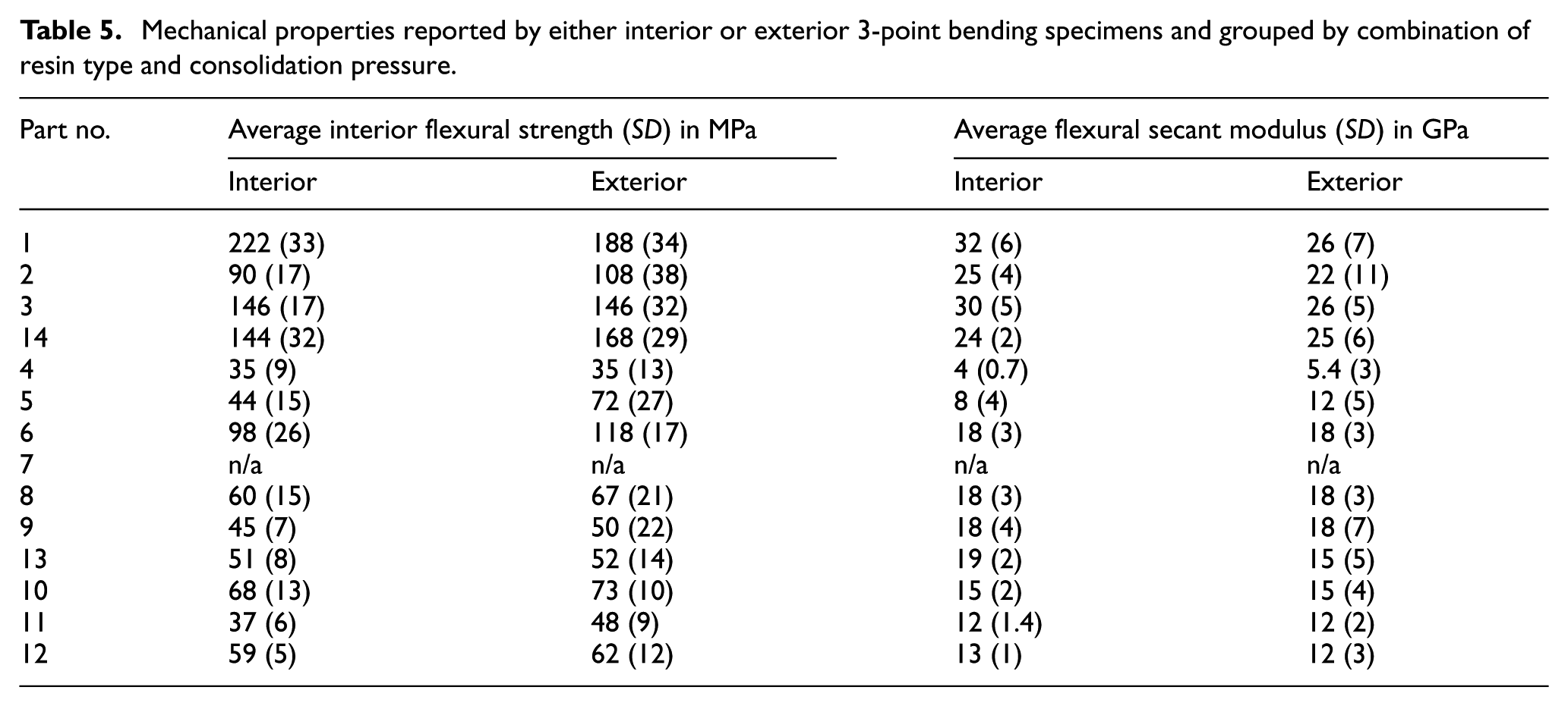
Mechanical properties reported by either interior or exterior 3-point bending specimens and grouped by combination of resin type and consolidation pressure.
Better mechanical properties due to higher consolidation pressure is expected, but the effect of resin formulation was initially surprising. However, basic resin formulations were utilized that did not contain adhesion promoting or fiber wetting additives. The cationic resin was based on a difunctional cycloaliphatic epoxy resin (and photoinitiator) while the free-radical system was based on a difunctional epoxy acrylate resin (no photoinitiator). Reactive diluents (monomers) were incorporated for viscosity reduction, but also affect other physical properties of the liquid (uncured) and solid (cured) composite resin matrix. Along these same lines, the carbon fiber itself is a commercial product with standard sizing and not necessarily a sizing designed for either chemistry, although in this case, adhesion by the cationic resin was clearly superior. The sizing on the fiber plays a key role in regard to resin/fiber compatibility, interaction, and overall composite performance.
Since the part’s interior was usually where poor wet-out was observed, mechanical properties for each part were measured separately for test specimens cut from the exterior and interior. Specifically, “Interior” indicates specimens cut from the middle 64 mm square within the 127 mm square part, whereas “exterior” specimens were cut from the outer 32 mm on the right and left sides of the part. Part 7 had poor wet-out and, thus, was considered an outlier. As before, cationic resin/high consolidation pressure specimens clearly have higher strength and stiffness values, that is, 2–3 times that of the low pressure parts. Flexural strength for exterior specimens is slightly higher than interior specimens, as would be expected. With regards to flexural secant modulus, there is no significant difference between exterior and interior specimens. Modulus for free-radical resin parts increases approximately 40% from low to high consolidation pressure. Standard deviation for strength and modulus are generally high for all parts as evidence of the high degree of variability with this new process.
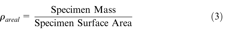
In an attempt to quantify the positive or negative effects of lightweighting (i.e. making thinner) on composite part performance, average flexural strength and secant modulus values for what were considered the “best performing” parts in each resin type/consolidation pressure category (Part No. 1, 6, 9 and 10) are normalized by dividing by their respective areal densities, ρareal, using
The “best performing” parts were chosen based on highest average values of flexural secant modulus and wet-out characteristics. The area densities and adjusted values are provided in Table 6. The superior performance, that is, strength and modulus, of the cationic resin infused using RI and consolidated at high pressure is amplified when considering areal density. Likewise, the effect of “lightweighting” on free-radical resin modulus is also shown.
Average flexural strength and secant modulus adjusted for areal density.
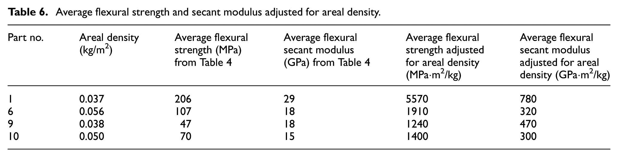
The “best performing” parts in each resin type/consolidation pressure category (1, 6, 9, and 10) were also tested for fiber volume and void volume fractions, and results are provided in Table 7. High pressure consolidation improved fiber volume fraction for the cationic resin parts by 60%, whereas it was only 32% for the free-radical resin parts. Void volume fraction decreased significantly for the cationic part and only slightly for the free-radical part. Negative void volume fraction, although not possible practically, are quite common results, since the reference mass used with ASTM D3171 is based on average part thickness and manufacturer-provided resin and fiber densities.
Fiber, matrix, and void volume fraction results.
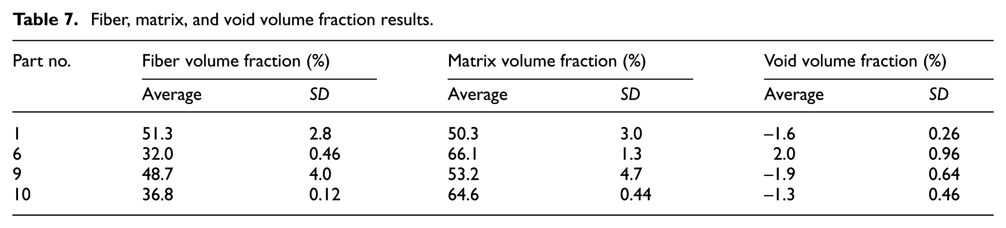
The same four parts were imaged in cross-section using microscopy. The significant thinning of the high consolidation Parts 1 and 9 is evident when comparing Figure 10(a) to (b) and (c) to (d). These images show that the low consolidation pressure parts have significantly more voids than their high pressure counterparts. Note that the large void in Figure 10(c) is a fiber pull-out from the cross-section polishing process.
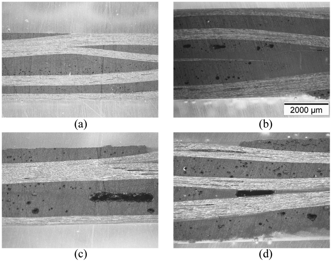
(a)–(d): Cross-sectional microscopy images of Parts 1, 6, 9, and 10 shown in (a)–(d), respectively. Scale in (b) is valid for all images.
Conclusion and future work
Feasibility of the EB-SETRI process has been successfully demonstrated for flat carbon/epoxy panels. Tooling design was the most challenging aspect given the rigorous process requirements. A successful design was achieved using a combination of FEA modeling coupled with an optimization algorithm for correctly shaping the SET mask and compression mold, experimental RI testing with a transparent mold and resin rheological analog to locate the inlet and outlet ports, Monte Carlo simulations to minimize EB attenuation, and FEA structural modeling of the thermoplastic composite compression mold (sandwich structure) to minimize mold deflection. From a limited number of parts infused then cured (due to high-power EB source access and cost) where resin type and consolidation pressure were varied, specimens cut from said parts were tested for degree of consolidation, geometrical uniformity, strength, and stiffness. Higher consolidation pressure resulted in thinner, stiffer, and stronger with fewer voids for the cationic resin, and differences were further exaggerated for lightweighting applications when accounting for areal density. The effect from higher consolidation pressure was expected, but resin effect clearly demonstrates the need for resin/fiber sizing compatibility.
With the basic process clearly demonstrated and manufacturing issues identified, future work planned includes more complex 3-D specimen geometries of commercial interest, more in-depth infusion modeling, and an improved tooling design that addresses many of the manufacturing issues observed during experimental trials. A focused energy usage and economic study is planned to compare EB-SETRI to autoclave parts and determine further advantages/disadvantages of the system. Furthermore, efforts will be made to optimize resin chemistry for both EB curing and compatibility with a particular reinforcement. Future work will include using dynamic mechanical analysis (DMA) to test for the glass transition temperature, Tg, of the material and Fourier transform infrared spectroscopy (FTIR) for testing the degree of cure. Another concern is how repeated EB irradiation affects the elastomer; for example, prolonged exposure may adversely affect the mask’s mechanical properties.
Footnotes
Acknowledgements
The authors would like to acknowledge several organizations for their support of this research work including Rensselaer’s Center for Automation Technologies and Systems (CATS); Vistex Composites, LLC; Rapid Cure Technologies, Inc.; and IBA Industrial, Inc.
Contributions to knowledge in the field
The novelty of the research discussed herein is a unique tooling design and manufacturing process that combines the best characteristics of resin infusion by vacuum, consolidation by specialized elastomeric tooling, and electron beam curing for high production of advanced thermoset composite parts in a potentially rapid, low-cost, and low-waste manner.
Declaration of conflicting interests
The author(s) declared no potential conflicts of interest with respect to the research, authorship, and/or publication of this article.
Funding
The author(s) disclosed receipt of the following financial support for the research, authorship, and/or publication of this article: The authors would like to thank the US National Science Foundation through Grant No. CMMI-1200847 and the New York State Energy Research Development Authority (NYSERDA) through Grant #43683 for funding this research.