
Abstract
Carbon fiber reinforced polymers (CFRP) are increasingly used in aerospace, military, and automotive applications due to their high specific strength and corrosion resistance. CFRP components usually require small-hole machining before assembly. CFRP parts are susceptible to defects such as tears and uncut fibers during hole machining. Ultrasonic-assisted drilling (UAD) contributes to the suppression of their defects. However, preliminary experiments revealed that the effect at different diameters is not the same. Therefore, this paper innovatively compares the effect of ultrasonic-assisted machining on the suppression of defects under different hole diameters and investigates the mechanism. The effects of machining parameters such as ultrasonic power, feed rate, and rotational speed on burr and tear defects of holes under different hole diameters are experimentally studied and theoretically analyzed. It was shown that the lowest defective machined holes were obtained at 50% (4 μm) ultrasonic power for all hole diameters, while higher ultrasonic power would result in an increase in machining defects. Compared with small hole diameters, there are relatively fewer uncut fibers at large hole diameters, but the tearing defects are more severe. The defect suppression effect of ultrasound is more pronounced at larger holes. The change in cutting force due to ultrasound is an important reason for the difference in machining defects. At a diameter of 6 mm, the longitudinal cutting force decreased by 58.7%, while uncut fibers and tearing defects decreased by 45.1% and 12.6%, respectively. This study can provide a theoretical basis for the selection of ultrasonic power and other parameters when machining holes of different diameters.
Keywords
Introduction
CFRP material is one of the most advanced composite materials. Compared with metal materials, it has excellent characteristics such as high specific strength and modulus, a low coefficient of thermal expansion, high temperature resistance, corrosion resistance, etc. 1 Thus, CFRP material is widely used in aerospace, military, automotive, and other fields.2–4 In the assembly process of CFRP parts, the machining of connection assembly holes is an indispensable step. 5 However, numerous studies of drilling on CFRP materials with laminated structures have shown that the machining is accompanied by various defects such as uncut fibers, tears, fiber pull-out, matrix degradation, matrix cracks, etc.6–10 Holes in composites create stress concentrations, and defects in the machining of holes have a significant effect on the stresses around the holes. Consequently, the final strength of the component is greatly influenced by the quality of the hole machining. 11 It has also been shown that machined surface texture and damage to holes will affect the fatigue behavior of the component, which in turn affects the life expectancy of the product. 12
Scholars have conducted a lot of research on the optimization of machining process and machining parameters for drilling holes in composites. K Giasin, et al. used a new environmentally friendly cryogenic cooling technique in a liquid nitrogen bath for the drilling of S2/FM94 glass fiber reinforced epoxy composite. The results indicate that the spindle speed and cryogenic cooling had the most significant influence on the cutting forces and surface roughness parameters, while the use of cryogenic cooling had the most significant influence on increasing the hardness and size of delamination at entry and exit sides of the holes. 13 I Boughdiri et al. analyzed the effect of cutting parameters and tool coating of twist drills on thrust, torque and hole quality during drilling of GLARE 2B laminates. The results show that feed has a significant effect on thrust and torque compared to spindle speed. 14
Besides, scholars have found that UAD can inhibit defects such as uncut fibers and tears in CFRP parts.15–18 Liu, Amin, and Li et al. utilized UAD with different shapes of grinding heads to process CFRP parts, and the experiments showed that ultrasonic vibration can play a role in reducing the cutting force during the machining process of these several grinding heads.19–21 Cong et al. used core drilling for UAD and analyzed parameters such as feed rate, cutting force magnitude, and machining temperature.22–25 Wang et al. analyzed the effect of changing the ultrasonic direction and frequency on the machining results.26,27 Huang et al. found that UAD can effectively reduce the average wear width of the cutter face by up to 13.0% by comparing UAD with normal drilling. 28 Krishnaraj et al. conducted an experimental study on CFRP thin plates with a full factorial design to determine the optimum cutting conditions by varying the drilling parameters, such as spindle speed and feed rate. 29 Ma et al. utilized the longitudinal-torsional-coupled UAD for drilling, and the experimental results showed that the method can reduce the cutting force, delamination and uncut fibers, while improving the surface quality of the hole wall. 30
In terms of mechanistic study of defects, J Saoudi et al. proposed a realistic model to predict the critical thrust of a multidirectional carbon fiber reinforced plastic plywood with a core drill bit in the layer leading to the exit ply caused by drilling and compared the proposed model, literature models, and stamping tests. 31 Davim et al. proposed a new technique to measure the adjustment of the delamination factor, which allows faster identification and quantitative analysis of defects by using numerical analysis of image recognition. 32 Lv analyzed the defects of delamination tearing and the causes of delamination by using methods such as microscopic morphology observation. 33
The above studies have deepened our understanding of the mechanism of UAD on CFRP parts. However, there are few reports regarding the influence of various process parameter settings on the machining effect of different hole diameters in the above studies. Therefore, in this paper, the uncut fibers and tearing defects at different diameters are analyzed through experiments, and the mechanism of the effect is analyzed. The study can provide a basis for the selection of the hole diameter of CFRP parts and the selection of processing parameters for these holes by UAD.
This article is divided into three main sections. Experimental setup and methods are discussed first, including the properties of workpiece materials, experiment equipment, experiment procedure, and measurement procedure. In the results and discussion sections, the results of orthogonal tests were analyzed by using Minitab to analyze the main effects of ultrasonic parameters, rotational speed and feed rate on the machining of different hole diameters. The morphology of the holes in the validation tests and the mechanism of machining by the chip force during machining were also analyzed. Finally, a conclusion recaps the main achievements of the project.
Experimental setup and methods
Properties of workpiece materials
CFRP processed prototypes are formed through carbon fiber prepregs that are laminated and thermoset. The prepreg, model T300, has a thickness of 0.2 mm and consists of unidirectional carbon fibers and epoxy resin. The specific mass of the epoxy resin is about 30%. The prepreg was laid in 15 layers on an aluminum mirror mold using the unidirectional layup shown in Figure 1(a), and then vacuumed and heat-set through a heat-set machine. The total thickness of the molded material is about 3 mm. As shown in Figure 1(b), prototypes were cut by a milling cutter with dimensions of 50 mm*50 mm. The specific performance parameters of the prototypes are shown in Table 1. (a) Material schematics; (b) Material prototypes. CFRP material parameters.

Experiment equipment
Based on a conventional CNC machine tool, the UAD system was designed to realize the longitudinal ultrasonic vibration of drill bit compound with drilling. As shown in Figure 2, the designed system consists of two major parts: a machining control system and an ultrasonic machining system. Experiment equipment.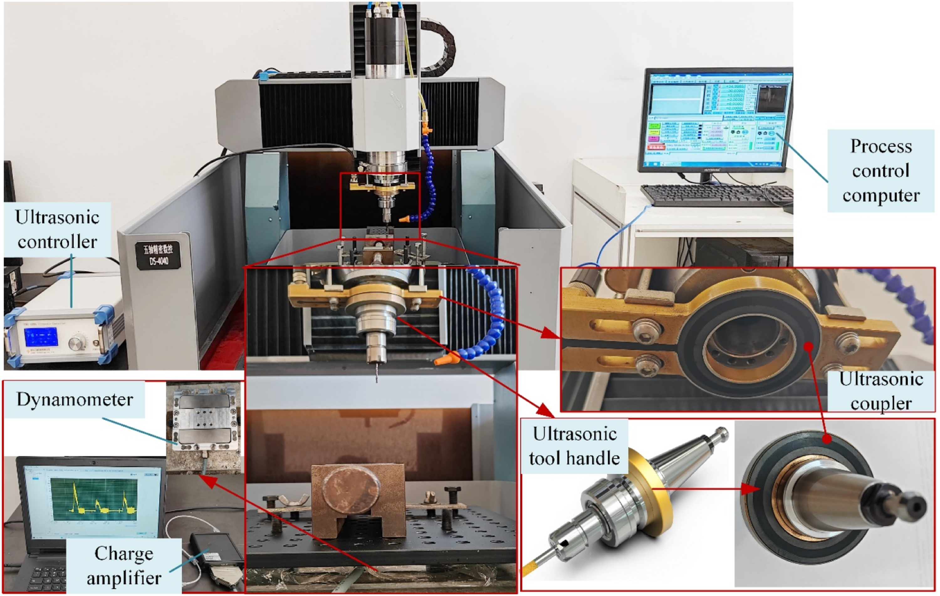
The machining system consists of a CNC computer and a maneuver handle, which can control the running trajectory of the machining system. The ultrasonic machining system is composed of an ultrasonic controller, an ultrasonic tool handle, and an ultrasonic coupler. The ultrasonic controller provides high-frequency electrical energy for the ultrasonic tool holder. Since the tool handle is a high-speed rotating part, the non-contact ultrasonic coupler is used to transmit the power through a wireless transmission mode. During processing, the gap between the ultrasonic tool handle and the ultrasonic coupler is maintained within 1 mm to ensure the reliable transmission of ultrasonic power. By this way, the tool vibration can stay steady according to the set ultrasonic power, and the frequency is controlled at near 20 kHz.
In order to further investigate the process mechanism, a dynamometer system (model ME-K3D120, Germany) was used to test the cutting force during the machining process. As can be seen from Figure 2, this force measurement system includes a force meter for converting force into an electrical signal and a charge amplifier to amplify the signal. The amplifier is connected to a computer through a USB port, and the data is collected or read through ME’s accompanying software.
Tool parameters.


Experiment procedure
Before the experiment, the relationship between the set ultrasonic power vibration and the actual amplitude was measured. An LK-G5000 series laser micro-displacement sensor with a light-sensitive head with a maximum sampling frequency of 100 kHz and a repeatability of 0.02 µm was used for the measure. According to the measured data in Figure 3, there is a linear relationship between the actual measured value of ultrasonic amplitude and the set power percentage. It means that, through the adjustment of ultrasonic power, the ultrasonic amplitude can be controlled in the range of 0–8 μm as required. Ultrasonic power and amplitude relationship.
Level of factors.

After that, a supplementary experiment was carried out to further analyze the influence of defects in the ultrasonic power with different holes. The experiment was taken with the fixed parameters of rotation and feed speed and the variable parameters of ultrasonic power and diameter of holes.
Measurement procedure
The machining defects, such as uncut fibers and tears, were observed by a 3D digital microscope (Model ALSVI 3DM-HD228S, China) to get the microscopic morphology. Referring to the literature,
34
the defects were quantified as indicators for the statistical comparison of each group of data.
28
The characteristic parameters were measured according to the method shown in Figure 4. The factor of uncut fibers, Fb, and the tear factor, Ft, were calculated according to equations (1) and (2), respectively. Measurement schematic of uncut fibers and tears.
The formulas are as follows
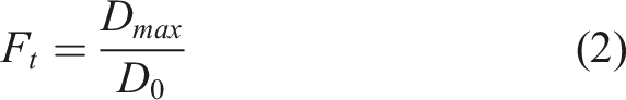
where S i is the area of the i-th uncut fiber in the processed hole; n is the total number of uncut fibers; D0 is the diameter of the processed hole; and Dmax is the maximum diameter of the uncut fiber coverage after processing. For the calculation, a circle is drawn with the center of the hole as the center, and the diameter of the smallest circle that can completely contain all defects is defined as Dmax.
Results and analysis
Orthogonal experiment results
After the test, the morphology of the machined holes was observed by a 3D digital microscope. Figure 5 shows the microscopic morphology of one of the machined holes. Figure 5(a) shows the morphology at the entrance of the hole, which is divided into four regions from the entrance to the exit according to the positional characteristics. The first area is the entrance to the hole, where a small amount of uncut fibers can be observed. The second region is the inner surface of the hole near the entrance, where almost no fibers are exposed, indicating that the epoxy resin and fibers were removed at the same time and that the surface processing effect is good. The third region is the inner surface of the hole near the exit, where a small amount of fiber exposure can be observed and the processing effect is reduced. In the fourth area, the exit, a large number of burrs can be observed. These unresected fibers and tearing defects can be clearly observed from the micrograph at the exit in Figures 5(b) and (d) are the microscopic images of the uncut fibers and tears. The material has been delaminated in many of the torn areas, which will seriously damage the structural strength of the workpiece, affecting its performance and life expectancy after assembly. 3D appearance of the machined hole: (a) entrance; (b) exit; (c) uncut fibers; (d) tearing.
After the experiment, the topography of the machined holes was observed using a digital microscope. Figure 6 shows the topography of one of the machined holes. It can be seen that although the entrance is relatively intact, there are obvious uncut fibers and tears at the exit. Lots of material delaminates with the tears, which will seriously damage the strength of the workpiece and affect the structural strength after assembly. Measurement of uncut fibers and tears.
Orthogonal experiment results.

Response of uncut fibers
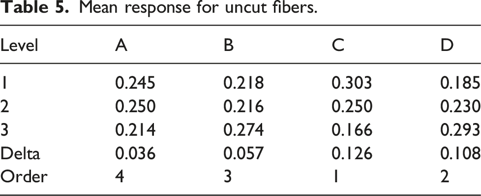
Mean response for uncut fibers.

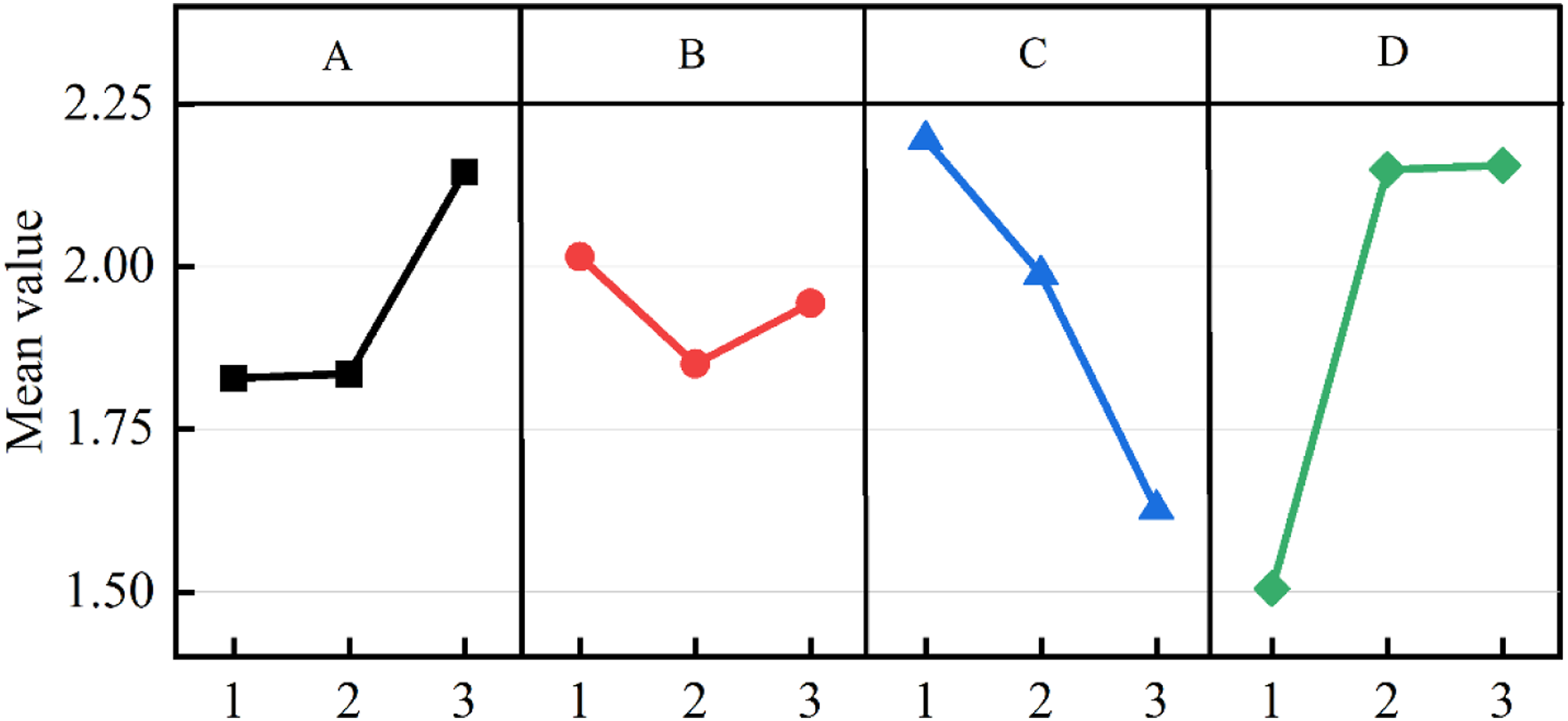
Main effects analysis of uncut fibers.
It can be seen that the rank of factors on the influence of Fb is CDBA. The rotational speed and feed rate effects are significant. As the rotational speed increases or the feed rate decreases, Fb decreases significantly. The effect of ultrasonics is also large. As the ultrasonic power increases, Fb decreases slightly at the beginning and then increases significantly. Fb is lowest when the ultrasonic power is 50%. This shows that when the ultrasonic amplitude exceeds a certain range, it will not be conducive to the control of uncut fibers. The effect of hole diameter on Fb is relatively weak. The Fb is significantly higher for hole diameters of 2 mm and 4 mm than that of a 6 mm diameter.
Therefore, the optimum factor level is A3B2C3D1: the diameter of the hole is 6 mm, the ultrasonic power is 50%, the rotational speed is 15,000 r/min, and the feed rate is 10 mm/min.
Response to tear defects
Mean response for Ft.

Main effects analysis of tears.
It can be seen that the rank of factors on the influence of Ft is DCAB. As with Fb, feed rate and rotational speed have a significant effect on Ft. When the feed rate decreases or the rotational speed increases, Ft decreases significantly. The effect of hole diameter on Ft is also significant. When the hole diameter increases from 4 mm to 6 mm, Ft increases significantly. The effect of ultrasonics on the tearing factor is relatively small. The degree of tearing is low when the ultrasonic power is at 50%. However, when the ultrasonic power reaches 100%, the degree of tearing will be serious.
From the above analysis, it can be seen that the optimal factor level is A1B2C3D1: the diameter of the hole is 2 mm, the ultrasonic power is 50%, the rotational speed is 15,000 r/min, and the feed rate is 10 mm/min.
Supplementary experiment
A supplementary experiment was taken to verify the correctness of the above conclusions and to analyze the effect of ultrasonic power on uncut fibers and tear defects in different hole diameters. In this experiment, the rotational speed was set at 15000 r/min and the feed rate at 10 mm/min. Meanwhile, the ultrasonic power was set at 0, 50%, and 100%, and the hole diameter was set at 2 mm, 4 mm, and 6 mm, respectively.
Result of defects
The magnified microscope image of each hole after machining is shown in Figure 9. The upward direction of the clamping direction is marked in the figure. In order to visualize the comparison, the images are enlarged in different proportions according to the different diameters of the holes. From the topography, it can be seen that the tears and uncut fibers are mainly concentrated at the bottom of the hole, and there are no obvious defects at the inlet of the hole. Comparing the appearance of the topography, it can be seen that there is a certain regularity in the uncut fibers and tears: Magnified microscope image.
First, there is a certain pattern in the location of uncut fibers and tears. From the entrance angle, the uncut fibers are basically located in two opposite quadrants, especially when the hole diameter is 2 mm and 4 mm. The detailed location is marked with red shading in Figure 9. The location of the tears is close to the uncut fibers, and the closer to the center of the tool along the fiber extension line, the higher the degree of tearing.
Secondly, there is a correlation between the defects of uncut fibers and tears. Uncut fibers and tears occur in the same layer of fibers, and finer uncut fibers are accompanied by smaller tears and delamination, while coarser uncut fibers are accompanied by larger tears.
The results are shown in Figures 10 and 11 of the quantified defects of uncut fibers and tears as Fb and Ft. From the pore size point of view, when the ultrasonic power is 0 or 50%, Fb is decreasing while Ft is increasing with the increase in hole diameters. In the case of conventional drilling, Fb decreases by 41.3% and Ft increases by 15.4% for a 6 mm hole compared to a 2 mm hole. Relationship between uncut fibers factor and hole diameters. Relationship between tear factor and hole diameters.

The Fb and Ft of the machined holes were significantly reduced when the ultrasonic power parameter was set to 50%. In the 2 mm, 4 mm, and 6 mm states, the Fb of the holes machined at 50% ultrasonic power decreased by 29.7%, 7.3%, and 45.1%, respectively, and the Ft also decreased by 11.0%, 6.9%, and 12.6%, respectively, as compared to the holes machined with traditional drilling.
The Fb and Ft of the holes were higher with the ultrasonic power parameter set at 100% than at 50%. At 2 mm, 4 mm, and 6 mm, the Fb of the processed holes increased by 23.8%, 36.2%, and 21.4% when the ultrasonic power parameter was set at 100% compared to 50%, and the Ft increased by 34.1%, 15.4%, and 9.5%, respectively. It can be seen that setting the ultrasonic amplitude parameter too high has a negative effect on the processing of CFRP holes. Therefore, the power of ultrasound should be controlled in industrial production.
The above analysis is similar to the conclusion obtained by orthogonal analysis, and it verified the correctness of the orthogonal experiment.
Cutting force analysis
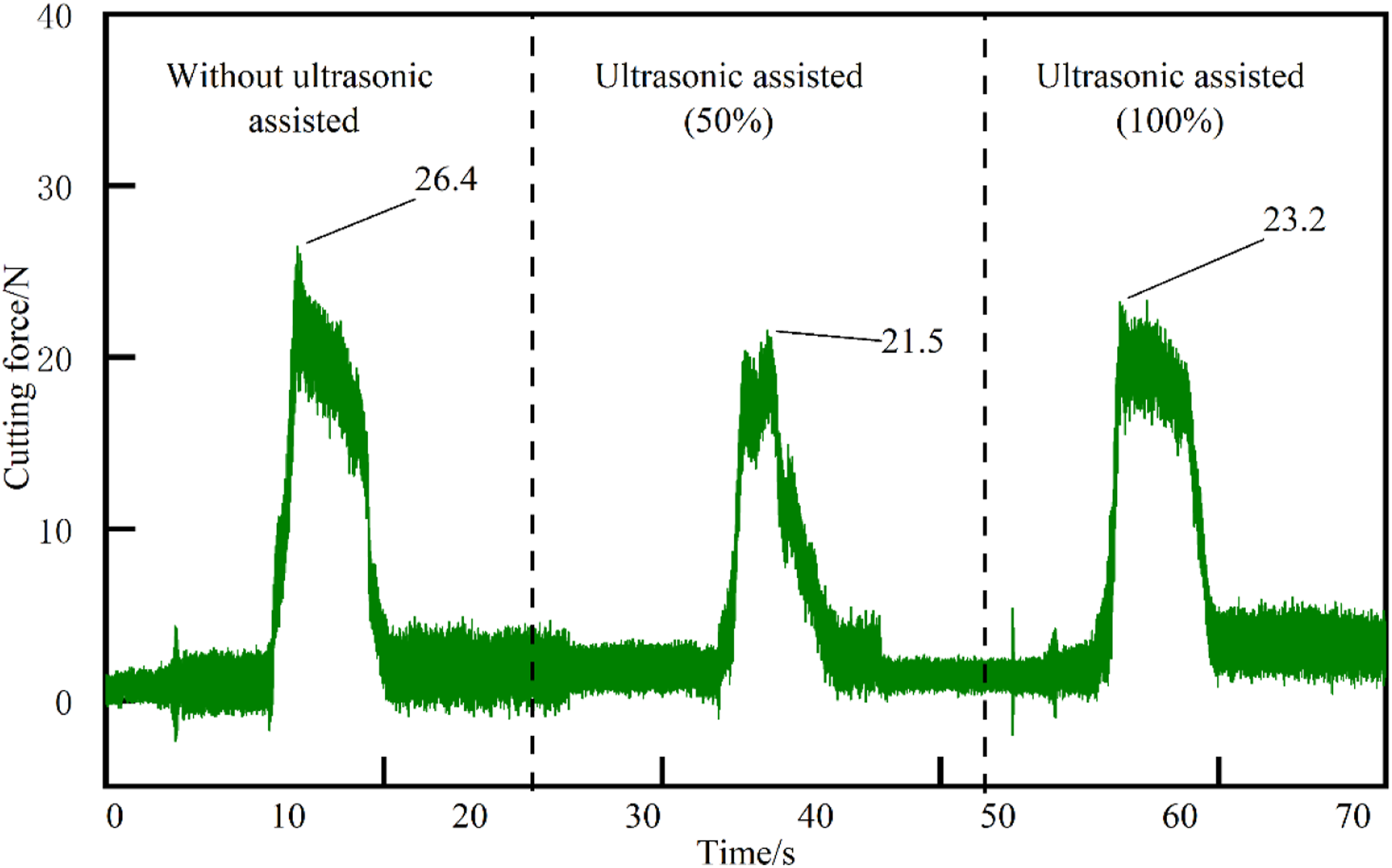
The cutting forces were recorded by a force gauge during the machining of the holes. Figure 12 shows the longitudinal cutting forces assisted by different ultrasonic amplitudes during the machining of a 6 mm-diameter hole. As can be seen, without ultrasonic assistance, the maximum longitudinal cutting force reaches nearly 120 N. When machining with 50% ultrasonic assistance, the maximum cutting force was reduced to 49.7 N, a decrease of 58.7%. When the ultrasonic amplitude was increased to 100%, the maximum longitudinal force was 86.3 N, which is lower than the case without ultrasonic assistance but is higher than the longitudinal force at 50% ultrasonic amplitude. Cutting force with a 6mm-diameter tool.
The same method can be used to obtain the cutting forces at 2 mm and 4 mm diameters in Figures 13 and 14. Cutting force with a 4 mm-diameter tool. Cutting force with a 2 mm-diameter tool.
It can be seen that the reduction in cutting force during ultrasonic-assisted machining is not as significant as in the case of a 6 mm-diameter tool in the case of 2 mm and 4 mm-diameters, but the trend of its effect is the same. The cutting force is minimized when the ultrasonic amplitude is set at 50%, while the cutting force increases instead when the ultrasonic amplitude reaches 100%.
Discussing
Based on the current study, the mechanism of tear generation can be depicted in Figure 15(a).35,36 Drilling produces delamination at the exit and is mainly due to the bending deformation of the uncut laminate under the longitudinal cutting force Fc. As the drilling deepens, the drilling support force Fs provided by the fiberboard decreases. When the difference between Fc and Fs exceeds the fiber matrix bonding force Fq, delamination and tearing will occur at the hole exit due to ply debonding. Defects generation: (a)mechanism; (b) cross section.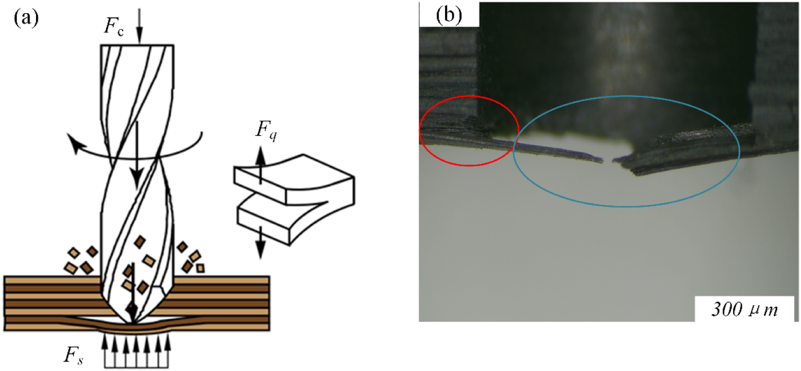
This mechanism can be verified by the microscopic image of the cross section of the above-tested machined hole in Figure 15(b). The deformation angle of the material can be observed at the locations circled in blue. In the areas circled in red, delamination of the material by the extrusion of the drill bit can be observed. Thus, greater cutting forces lead to an increase in delamination thickness, which causes deeper tearing driven by the circumferential force of the drill. After delamination and tearing, material is not sufficiently supported during cutting, and materials are left as uncut fibers. When Fc is high, delaminate will happen early. In this case, the delaminated fiber layer is thicker and the uncut fibers are coarser.
Therefore, the cutting force during machining plays a key role in the generation of defects. Figure 16 shows the combined analysis of ultrasonic amplitude, cutting force, and Fb and Ft that characterize the level of defects when machining a hole with a diameter of 6 mm. From the figure, it can be seen that the longitudinal cutting force decreases by 58.7% due to the intermittent cutting effect when machining is assisted by 50% of ultrasonic power. And at this time, the defect factors Fb and Ft decreased by 45.1% and 12.6%, respectively. When the ultrasonic power was increased to 100%, the cutting force increased, while Fb and Ft also increased. This shows that there is an intrinsic correlation between the optimization of ultrasound-induced defects and the reduction of cutting forces. Relationship between ultrasonic power, cutting force, and defects.
In addition, the analysis of the cutting forces showed that the change in diameter also caused a significant change in the cutting forces, which increased significantly as the diameter increased. However, due to the increase in holes, conditions such as cutting lubrication have been better improved, and the material removal capability has been enhanced. Therefore, the change in cutting force due to diameter did not directly lead to an increase in defects, as in the case of ultrasound.
Conclusions
To study the effect of parameters on defects in CFRP parts during UAD of different diameter holes, a series of experiments were undertaken. The influence of each factor on the defects was analyzed through morphology observation, mean response analysis, and main effects analysis. The conclusions obtained are as follows: (1) The rotational speed and feed rate have a greater effect on the hole defects. The experimental results at three different diameters show that increasing the rotational speed and feed rate can suppress the defects. Ultrasonics and hole diameter also have an effect on defects, but to a lesser extent than rotational speed and feed. (2) The burr factor and tear factor were significantly reduced with 50% ultrasound (amplitude of about 4 μm)-assisted machining. When machining a 6 mm hole, the uncut fibers and tearing of the machined hole decreased by 45.1% and 12.6%, respectively, when the ultrasonic power was set at 50% compared with 0. When the ultrasonic power was set to 100% (with an amplitude of about 8 μm), there was a substantial increase in unremoved material and tearing defects. Therefore, in engineering applications of ultrasound-assisted machining, the ultrasound amplitude should be controlled within 4 μm. (3) The change in cutting force is an important reason for the change in defects under ultrasonic assistance. When the ultrasonic power was set at 50%, the cutting forces were reduced at all diameters, along with a decrease in the degree of burr defects and tearing defects. The cutting forces were 58.7% lower for the 6mm-diameter machined hole at 50% ultrasonically assisted machining than for conventional machining.
Footnotes
Acknowledgments
The authors would like to express their sincere acknowledgement to the Experiment Center of Yangzhou University for providing measurement support for the experimental study.
Declaration of conflicting interests
The author(s) declared no potential conflicts of interest with respect to the research, authorship, and/or publication of this article.
Funding
The author(s) disclosed receipt of the following financial support for the research, authorship, and/or publication of this article: This work was supported by the National Natural Science Foundation of China (52175438, 51775484), Jiangsu Province Postgraduate Highlights Study Plan Project of JITRI Institute, and the 2023 Basic Science (Natural Science) research project of universities in Jiangsu Province.