
Abstract
Fiber-reinforced plastics are known as advanced composite materials thanks to their high strength and lightweight features. Carbon fiber reinforced polymers (CFRPs) are one of the high-performance and high-cost fiber-reinforced polymer (FRPs) materials. They are used in several high-performance engineering applications such as motorsports, marine, aviation, energy and defense industry. The cost of carbon fiber is higher compared to many other materials, more competitive and cost-effective productions will spur the demand for composite parts exponentially. Thus, hybrid laminate composite containing carbon and glass fiber materials were manufactured as an alternative for CFRP materials. Because using glass fiber prepreg instead of carbon fiber prepreg will lead the material to become cheaper. However, machining of the FRP materials is still an important issue. For this reason, the present study is focused on the mechanical and machining performance of the polymer hybrid and carbon fiber epoxy composites.
Keywords
Introduction
CFRPs are widely used in high-tech applications such as aerospace, automobiles, sports equipment, and wind-turbines because of their high strength-to-weight ratio properties.1–5 There are several production methods use for manufacturing of FRPs such as hand lay-up, vacuum bagging, vacuum infusion, resin transfer molding (RTM), pultrusion, filament winding, sheet-bulk molding compound (SMC-BMC), spray-up, centrifugal molding, prepreg compression molding and curing with autoclave. 6 Although there is a great number of alternatives to produce FRPs, autoclave is still known as the best way to produce composites with high strength and high surface quality. 7 However, in terms of setup and operating costs, autoclaves still have some challenges that need to be overcome. 8 Not only the researchers but especially the high technology industries are looking for out of autoclave (OoA) methods to reduce the cost. 9 Recently, there is a considerable amount of studies about OoA production method that exists by researchers via using prepreg.10–14 The basic principle of the curing prepreg is heating and pressurizing the material due to a regime. This regime is known as the cure cycle in the composite industry. Cure cycle generally recommended by the supplier. 15
In today’s modern aircrafts such as the F35 Lightning II, the Airbus A380 and the Boeing 787 Dreamliner contain CFRP parts due to the lightweight and structural strength demands.5,16 High strength properties of the CFRP bring with tough machining characteristics. 17 An airframe needs thousands of drilling processes. In an aircraft assembly operation, delamination defects are responsible for 60% of total rejection. 5 Tool wear in drilling is a common problem and increases the manufacturing cost. CFRP machining needs high-performance drill bits due to intense tool wear. Using polymer hybrid composite materials (PHCM) is a promising option to get similar mechanical strength with low manufacturing costs.
Pre-impregnated resin systems (prepregs) are placed in the key position to produce FRPs with higher quality final products. Reducing weight and production costs without reducing the strength of the materials is a hot topic for the composite material industry. For this reason, developing new hybrid FRP products attracts more attention than ever by the composite industry. On the other hand, assembling the FRP materials among themselves and with other materials is another challenge that needs to be handled. They need to be drilled or machined properly to not lose its strength. The present study focused on the defects and failure of carbon and carbon-glass hybrid laminated materials during the machining process. Carbon and glass/carbon-epoxy prepregs were cured with a compression system due to a cure cycle (temperature and pressure regime). According to the conducted tests while thrust force and cutting temperatures are obtained for PHCM are lower than CFRP, drilling of CFRP gives better results in terms of delamination and surface roughness. Industrial competitive alternative composite structures will be the solution for cost savings. The main motivation of this study is to report an alternative composite material with more effective drilling characteristics but giving a little compromise on the mechanical strength than CFRPs.
Experimental procedure
Test material
Hybrid carbon/glass fiber reinforced () and only carbon fiber reinforced epoxy matrix polymer composites were fabricated by heat-assisted press bench. Glass and carbon fiber/epoxy resin prepregs were supplied from Kordsa Company. A schematic representation and the experimental setup are given in Figure 1(a). The impregnated layers are cut and laid down into the open mold. Prepregs were placed between the hot plates with backing papers. Two prepreg forms were fabricated using the same epoxy resin. A 600 g/m2 twill woven glass and carbon prepregs were used. The average thicknesses of carbon and glass fibers are 0.46 mm, 0.49 mm respectively. Prepreg angles comprise an all 0/90° fiber orientation. The fiber to resin volume ratio was 70-to-30 for both prepregs. Eight layered carbon prepregs were placed between the plates to cure 3 mm benchmark specimens. Then four glass and four carbon prepregs were laminated as two of the carbon prepregs are placed upper layer while two of the carbon prepregs were placing the bottom layer. In this way, glass prepregs were placed in the middle of the carbon layers. The configuration of the layers can be seen in Figure 1(b). The cure cycle of the prepregs contains one ramp and one isothermal hold at 120°C and 7 bars for 1 h.

(a) The production setup: Cemilusta brand SSP 180 laboratory test press, (b) the configuration of layers.
Three-point flexural bending test
Three-point bending test was applied to the CFRP and PHCM composite samples at room temperature (23°C) and humidity (55% RH) with Instron 4411 test machine to determine the mechanical properties. The three-point bending tests were performed at a crosshead displacement of 1 mm/min. Tests were applied according to ASTM 790 standard on rectangular specimens (3 × 10 × 60 mm) with a span length of 48 mm. Each type of composites was tested six times for repeatability.
Drilling set up, optimization and validation procedure
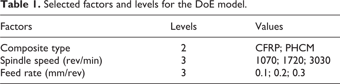
A set of three holes were drilled for each combination of input parameters under dry machining condition. Figure 2 shows the drilling setup. The drilling performed with a Toss United TU5032B vertical drilling machine. Thrust force data recorded with a Kistler 9272 piezoelectric drill dynamometer and a 5070A model amplifier. The data acquisition process performed with DynoWare software. A FLIR-A325sc model infrared camera was used to record drilling temperatures. The infrared camera placed 50 cm above the workpiece at an angle of 60°. Thus, the measurement performed at a drilled hole surface from 5 mm below the upper ply. Thermal images give information about chip formations. FLIR R&D software was used to calculate the mean temperatures of the selected areas. The performance comparison of CFRP and PHCM in drilling was considered with conducting experiments using selected factors and levels, as seen in Table 1. Response surface methodology (RSM) was used to evaluate experimental results by using Minitab 19 statistical software. While developing the model, feed rate and spindle speed were defined as a continuous factor. The relationship between the independent variables and the responses in RSM is defined by a second-order polynomial model given below.

where y is predicted response, β0 is constant, βi, βii and βij represent coefficients of linear, quadratic and interaction terms respectively. While X shows the coded variables, ε indicates the error. 18

The experimental setup.
Selected factors and levels for the DoE model.
The variance analysis of the experimental results was performed in the 95% confidence interval for P values. 19 ANOVA tables obtained for the test results are given in Supplementary Appendices A and B. Some of the important parameters showing the hole quality in the drilling process are delamination and surface roughness. Hole entry and exit images were filtered using the ImageJ tool and effected areas were calculated as peel-up and push-out delamination factors. 2D Mitutoyo SJ-301 device was used for surface roughness measurements. Average surface roughness was obtained by averaging the measurements taken from three different points of each hole.
Results
Comparison of the three-point flexural bending test
The three-point bending test result of the composite samples are given in Figure 3(a) to (d). CFRPs exhibit approximately 20% higher flexural strength compared to PHCMs, as seen in Figure 3(a). This result is expected and can be explained by higher the bending strength of the carbon fiber. Similarly, it is revealed from Figure 3(b) that CFRPs show higher flexural modulus only about 7% than PHCMs. Average flexural strain values are given in Figure 3(c). Accordingly while CFRP exhibits under 2% flexural strain hybrid composite exhibit over 2%.
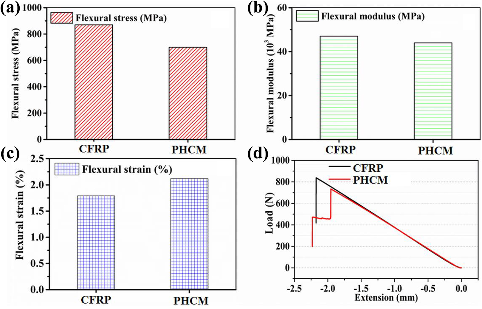
Three-point bending test results; (a) flexural stress, (b) flexural modulus, (c) flexural strain, (d) load-extension curves.
Figure 3(d) shows the load-extension curves of the composite samples during the bending tests. While CFRPswere broken after reaching a maximum load, PHCMs showed a sudden load discharge after reaching a maximum load and continued to bend by carrying at this low load level. Figure 3(d) shows that the carbon fiber layer on the outer part broke firstly and then the glass fiber layer continued to carry the lower load for a while and broke at last.
Figure 4 indicates the defects after the three-point bending test. The failure of carbon fiber originated from the top layers. The damage in CFRP composites is mostly in the first 5 layers of folding inner surface, in the form of matrix fiber interface separation and fiber breakage. Fiber fracture in the carbon layers was the main failure mode for the both composite configurations. No damage is observed in three to four layers that are in contact with the stamp under the static three-point bending load. The damage behavior of the PHCM was different. While four layers of GF in the middle part did not show any significant damage, rupture damage occurred in the carbon fiber layers in the upper and lower surfaces which indicates that the hybrid material is advantageous against sudden ruptures by in addition to Figure 3. Therefore, structural design engineers can reduce the risk of catastrophic failure by using the PHCMs.
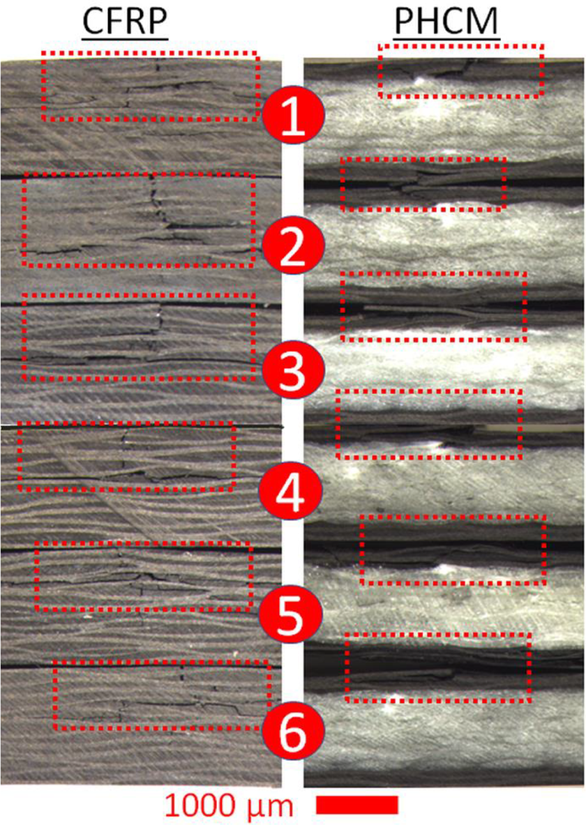
Crack propagation of the three-point bending test.
Evaluation of thrust force during drilling operation
The analysis of drilling force and defects are the basic indicators for the machinability of composite materials. During drilling cutting force at vertical direction is evaluated as the thrust force. 20 Figure 5 shows the main effect and contour plots for thrust force comparison of CFRP andPHCMs. The thrust force increases with increasing spindle speed and feed rate for both materials. The highest thrust force level obtained when drilling CFRP reinforced composite material. Drilling PHCMneeds 40% less thrust force than CFRP. Thrust force during CFRP drilling is more sensitive against incrementation on spindle speed and feed rate thanPHCM.
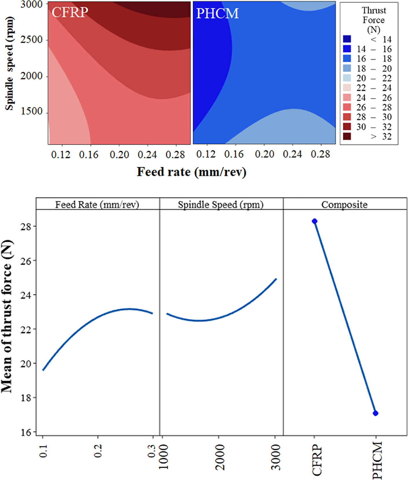
Thrust force graphs for different cutting parameters and main effect plots.
When drilling with the lowest levels (1070 rpm–0.1 mm/rev) of the parametric factors thrust force calculated about 22 N for CFRP composite. RSM analysis results for PHCMwith 0.1 mm/rev level of the feed rate factor show that thrust force is hardly affected by the increase of spindle speed. Moreover, drilling PHCMwith the highest levels (3030 rpm–0.3 mm/rev) of the parametric factors, the thrust force is only 14 N. Thus, it can be revealed that drilling of PHCMis more effective.
Temperature analyses during drilling operation
Tool life and geometrical tolerances are sensitive to temperature so excessive temperature level is a restrictive condition during drilling. Both drill bit and test material temperature measurements during drilling lead to the determination of the optimum parametric levels. Elevated temperature is mainly transferred from the system with the resulting chips. Residual heat on the system disperses among the tool and workpiece.
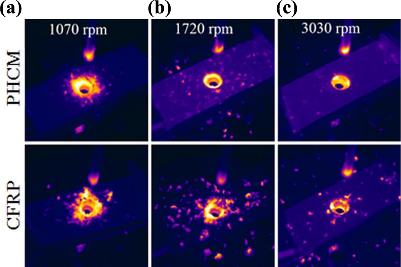
In Figure 6 average drill and hole temperatures of CFRP and PHCMare given. According to these graphs, higher temperatures occurred at drill bits and holes during drilling of CFRP composite. The thermal conductivity coefficients of the carbon fiber and glass fiber materials are 40 W/mK and 1.3 W/mK, respectively.21,22 Although the thermal conductivity of glass fiber is much lower than carbon fiber, lower temperatures occurred during the drilling of glass fiber materials. This is an indication of a harsh and high frictional drilling environment that creates high temperature during drilling of CFRP. Higher drilling temperatures during drilling of composite materials may cause problems such as burning of the matrix phase.22,23 This situation may limit drilling operations by avoiding using high cutting speeds. By examining mean graphs of the average hole and drill temperatures, it can be concluded that 0.3 mm/rev feeding rate, 3030 rpm spindle speed and PHCMsare optimal conditions in terms of cutting temperatures.

Average (a) hole and (c) drill temperatures, main effect plots for (b) hole and (d) drill temperatures
In Figure 7 differences in chip formation can be observed. In general, it can be said that glass fiber chips are larger than carbon fiber chips. Also, it was found that increasing spindle speed increases chip size where increasing feed rate does not affect chip size and formation. However, all the chips obtained in this study have a formation that will not adversely affect the drilling process.
Chip formation after drilling of CFRP and PHCMwith 0.2 feed rate and different spindle speeds.
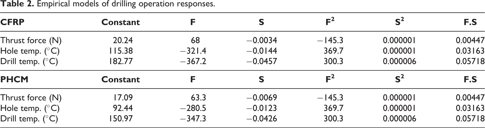
Regression equations
The regression equations obtained after evaluating the test results according to RSM are given in Table 2. Here, the coefficients of linear, interaction and quadratic terms are presented separately for each response. The ability of the regression equations to estimate the test results is expressed by the R2. Predicted R2 shows the ability of prediction of possible new observations with the obtained regression equation.24–26 R2 and R2 (pred) values for thrust force are 93.85% and 91.79%, respectively. After regression analysis for drill temperature, R2 and R2 (pred) are 97.52% and 96.62%, respectively. R2 and R2 (pred) for hole temperature are 97.85% and 96.88%, respectively. As can be seen, the success of predicting the experimental results of the established model is high enough.
Empirical models of drilling operation responses.
Assessment of delamination and surface roughness
Delamination directly affects the deterioration of the dimensional accuracy and surface finish of the drilled hole. Thus, it can cause the rejection of products coming to the assembly that stage up to 60%. 27 The natural abrasive effect of the fibers decreases the life of the tools and increases the delamination. For this reason, it is very important to reveal the optimum working conditions that minimize delamination. 28 OM images of delamination obtained at the entry and exit of the hole are given in Figure 8. Accordingly, high feed rate increases delamination both at the hole entry and at the exit. Likewise, delamination for PHCM appears to be higher than CFRP. Glass fiber has a negative effect on delamination. Graphs obtained for 2D delamination factors are given in Figure 10(a) and (b). The delamination factor is calculated by the equation given below:


A set of selected micrographs for evaluating the peel-up and push-out delamination.
Here, Adel refers to the damaged area with the hole, while Anom refers to the nominal hole area. 29 The defects observed in Figure 8 have gained even more clarity after 2D delamination factor measurements. PHCM clearly appears to cause higher delamination defects than CFRP. The increase in spindle speed caused a significant decrease in peel-up delamination defects. Even the high feed rate almost neutralizes the effect of increasing delamination. These results support the previous studies.30–32 The fact that the fibers are more undamaged and faster separated from the surface as soon as the tool enters the material thanks to the effect of the high spindle speed. All this process is thought to reduce the peel up delamination defect.
Surface roughness is another important parameter in drilling operations. High surface roughness negatively affects important abilities such as wearing, fatigue and surface friction. 33 The graphic obtained for surface roughness measurements is given in Figure 10(c). Likewise in delamination evaluation, it is seen that CFRP has a better roughness than PHCM. However, increased feed rate and spindle speed significantly affect negatively surface roughness. While the delamination effect decreases with increasing cutting speeds at the hole entry and exit, different results were obtained for surface roughness. This result differs from the literature in terms of surface roughness. 30 When the OM images of the hole inner surfaces given in Figure 9 are examined, the fibers have a rougher and damaged structure with increasing cutting speeds. On the other hand, for PHCM hybrid material, the glass fiber layer appears to wear more than CFRP due to the higher stiffness of the carbon layers.

OM micrographs for comparison of the hole surfaces.
Discussion
Generally, glass, carbon or aramid fibers are preferred as reinforcement while thermosetting and thermoplastics are preferred as matrix during FRP production process. The machining of these parts is the next operation for assembly. Drilling is the most common machining operation.34,35 However, CFRP parts exhibit a very high abrasive wear effect on the drilling tool. 4 Besides delamination, microcrack, uncut fibers, overheating damages can occur to the composite parts after drilling. 36 Process parameters and drill bit characteristics are the factors that affect the formation of these defects.37,38 Cutting force/torque, delamination, uncut fibers and tool wear characteristics are the basic evaluation indicators about machinability of FRPs. 3 Drilling process parameters like spindle speed, feed rate, and generated temperature influence on these characteristics.

In case of the orthogonal cutting in drilling operation of a unidirectional fiber reinforced polymer material, the fiber-cutting angle (θ) depends on the starting orientation of tool edge (ϕo) and the spindle speed (n). Chip removal mechanisms of unidirectional FRPs alternates in line with the function of the fiber-cutting angle.2,3 Therefore, fiber reinforcement orientation of different composite materials is the same comparing drilling properties in this study. Figure 10(a) and (b) show a comparison of the delamination characteristics. PHCM exhibits a little more delamination, because the higher tendency for bending of glass fiber caused the progress of delamination. Push-out delamination was greater than peel-up with higher amounts of damage generated for both types of composite.

Comparison of the hole characteristics: (a) peel-up delamination, (b) push-out delamination, (c) surface roughness.
In most cases, the strength of carbon fiber is higher than glass fiber resulting strength of a hybrid composite between carbon and glass fibers mechanically. However, on the condition that the strength of the glass fiber is close or higher than the carbon fiber, it is possible to reach and pass the strength of the carbon fiber for the hybrid composite. Dong et al. 39 obtained results confirming this situation in terms of flexural strain. Pandya et al. reported that hybrid composite showed mean tensile stress and strain values while the carbon fiber exhibits higher strength and glass fiber has higher strain values. 40 Zhang et al. 41 found out similar results in terms of stress and strain values. Moreover, they stated that the hybrid composite exhibits more matrix fractures than reinforcement failure because of the brittle characteristics of the carbon fiber. Therefore, using hybrid composite can be an effective chouse for avoiding brittle and catastrophic failure. Hybridization increased the flexural strain of the composite material. During drilling, brittle cracks were also detected at the hole surface of carbon fiber-reinforced composite. In this drilling advantage of the hybrid composite, design engineers will ensure to provide for ductility and avoiding brittle failure in case of the desired strength.
It is necessary to make cost comparisons in terms of engineering management. The costs of raw materials and manufacturing of the components are the main factors affecting the total production costs. The cost of carbon fiber raw material used in this article is 30 $/m2, while the cost of glass fiber is 7.5 $/m2. The unit raw material cost per unit of the CFRP structure consisting of a total of eight layers is $240, while it is $150 for the hybrid composite containing four layers carbon fiber and four layers glass fiber. Since the epoxy matrix material has not changed, it doesn’t affect in comparison. As a result, hybrid composite is 37.5% cheaper in terms of raw materials. In terms of machining costs, due to the high abrasive effect of carbon fiber, in many studies where tool life is evaluated, it is necessary to renew a tool in five holes depending on the desired size and surface quality. According to the measurement results of this study, the required thrust force is 40% less for hybrid composites. The cost of HSS-G drill bits in the study is 2$/piece. Comparing the machining cost for 100 holes is 40$ for CFRP and 24$ for hybrid composite. Therefore, the drilling cost of the hybrid composite is 40% less. There are side gains on indirect costs like depreciation of a drilling rig and electrical expense due to the 40% lower thrust force in hybrid composite machining.
Conclusion
An alternative for CFRPs are taken into consideration for studying the drilling characteristics by varying the process parameters. The results of this study can be listed as follows:
- Thrust force and cutting temperatures obtained for PHCM are lower than CFRP.
- CFRP gives better results when evaluated in terms of delamination and surface roughness. However, they are small negligible differences.
- In applications requiring high hole quality and precision, CFRP can be preferred in terms of both mechanical strength and machinability performance with respect to hole quality. However, this will significantly increase the both material and machining costs.
- In operations where lower hole quality is required, PHCM can be preferred to reduce the cost and increase the tool life.
- Cost contributions of using the PHCM are 37.5% cheaper raw material and 40% less machining cost.
Supplemental Material
Supplemental Material, sj-pdf-1-ppc-10.1177_09673911211020620 - A comparative study of mechanical and machining performance of polymer hybrid and carbon fiber epoxy composite materials
Supplemental Material, sj-pdf-1-ppc-10.1177_09673911211020620 for A comparative study of mechanical and machining performance of polymer hybrid and carbon fiber epoxy composite materials by A Tamer Erturk, Eser Yarar, Fahri Vatansever, Alp Eren Sahin, Mert Kilinçel and Yakup Okan Alpay in Polymers and Polymer Composites
Supplemental Material
Supplemental Material, sj-pdf-2-ppc-10.1177_09673911211020620 - A comparative study of mechanical and machining performance of polymer hybrid and carbon fiber epoxy composite materials
Supplemental Material, sj-pdf-2-ppc-10.1177_09673911211020620 for A comparative study of mechanical and machining performance of polymer hybrid and carbon fiber epoxy composite materials by A Tamer Erturk, Eser Yarar, Fahri Vatansever, Alp Eren Sahin, Mert Kilinçel and Yakup Okan Alpay in Polymers and Polymer Composites
Footnotes
Acknowledgments
The authors thank the Advanced Material Laboratory at Kocaeli University Technopark for supporting the experimental study. The authors gratefully acknowledge the support of the Scientific Research Coordination Foundation (BAP Unit, project no FHD-2020-1579) of Kocaeli University.
Declaration of conflicting interests
The author(s) declared no potential conflicts of interest with respect to the research, authorship, and/or publication of this article.
Funding
The author(s) disclosed receipt of the following financial support for the research, authorship, and/or publication of this article: Scientific Research Coordination Foundation (BAP Unit, project no FHD-2020-1579) of Kocaeli Universit.
Supplemental Material
Supplemental material for this article is available online.
References
Supplementary Material
Please find the following supplemental material available below.
For Open Access articles published under a Creative Commons License, all supplemental material carries the same license as the article it is associated with.
For non-Open Access articles published, all supplemental material carries a non-exclusive license, and permission requests for re-use of supplemental material or any part of supplemental material shall be sent directly to the copyright owner as specified in the copyright notice associated with the article.