
Abstract
Carbon fiber reinforced plastic (CFRP) composites have been widely used in engineering. This paper investigates the effect of composite z-pin (polyimide fiber/epoxy resin) on flexural properties of skin/stringer composite structure with different z-pin densities and diameters. Compared with unpinned specimens, the peak loading and energy absorption of z-pinned specimens are increased by 98% and 9 times, respectively. Parameterized research indicates that the optimal z-pin density is 1.35%. And thin z-pins are beneficial to improve the peak loading and energy absorption, which attributes to more total contact area of z-pins. The statistical results present that z-pin pre-hole inserted (ZPI) process can significantly reduce initial damages of z-pinned specimens compared with Ultrasonically Assisted Z-fiber (UAZ) process. Specifically, the z-pin inclination angle is decreased by 60%, and the initial damages in eye-like zone are prominently reduced. The z-pin makes the specimen exhibit the quasi-brittle behavior under flexural loading by playing a bridging role, which makes the flexural properties of specimens prominently increased. In addition, the “snubbing effect” will enhance the bridging effect of z-pins, but it will lead to inter-fibers debonding, splitting, and shear failure of z-pins.
Introduction
The high specific strength, high specific modulus, and light-weight properties of carbon fiber reinforced plastic (CFRP) composites make them suitable for various applications with the weight-reducing design requirement, especially in the ordnance and aerospace field.1–3 In the engineering field, the prevalent form of CFRP composite components is the skin-stringer structure.4–6 At present, the connection method of skin-stringer structures is usually bonding or mechanical joints. However, the bonding strength depends on the bonding process, which is difficult to control the bonding quality. 7 For the mechanical connection, the defects of hole damage, hole edge stress concentration, and increased weight seriously affect the connection effect. 8 Albeit the stitching, 3D weaving, and tufting connection are beneficial, they are usually used in conjunction with the liquid forming process, such as resin transfer molding (RTM). 9 However, they do not meet the demand for prepreg stacking forming.
In order to resolve these limitations, it is necessary to adopt the new connection method, which is friendly to intralaminar mechanical properties, and prevents the skin/stringer interface from debonding. Therefore, the z-pin technology is developed from stitching technology, in which discrete z-pins are inserted into the uncured laminates as a mechanical link between the adjacent plies of the laminates leading to achieving the convenient and effective connection.10–12 At present, the z-pin technology is mainly used in three aspects 13 : (1) interlaminar enhancement for composite structures, (2) the connection of composite structures, and (3) core materials for composite sandwich structures. Besides, the z-pin technology is widely used in the connection of composite structures. For example, the z-pin technology was used in the F/A-18 E/F fighter. Z-pins were inserted into the fuselage section and intake port instead of the traditional mechanical connection, which replaced 4600 mechanical fasteners, reduced weight by 17 kg per aircraft, and the cost of $83000. 14
NASA-funded research
15
indicated that the z-pin technology could be used as a connection scheme for the integral forming of composite fuselage, which was low-cost and high efficiency. Greenhalgh
16
et al. compared the effect of the resin bonding technology and the z-pin reinforced technology on T-joints. The results showed that z-pins caused additional energy absorption, which made the cracking propagate steadily. However, the peak loading was significantly increased. In contrast, the effect of resin bonding was little, but the cracking propagation was steady. Javier
17
et al. proposed a low-cost T-joint configuration, which directly removed the stiffened strip edge, and the web end was directly connected to the panel by z-pins. The experimental results showed that specimens could obtain the same connection capacity as the panel/stiffened co-curing connection, but the flexural bearing capacity of specimens was poor. Allegri
18
et al. found z-pins did not improve the stiffness and initial failure loading of flange-to-skin bonding, but they were effective for raising ultimate pull-out failure strength and failure displacement. These results were confirmed in the investigation of Koh
19
et al. Moreover, the above properties were improved significantly with the z-pin volume fraction. In the past few years, NASA
20
proposed a simplified configuration of skin-stringer structure, as shown in Figure 1. Based on that, some studies6,15,21 had shown that the cracking generated at the bonding interface could simulate the practical failure of large skin/stringer structure during the loading. Schematic diagram of the simplified configuration.
Traditionally, z-pinned specimens are fabricated by Ultrasonically Assisted Z-fiber (UAZ) process, which is the firstly developed and the widely used in engineering. 22 However, the previous research show that inserted z-pins could introduce initial damages in laminates, which leads to the reduction of in-plane properties.23–25 Recently, the z-pin pre-hole inserted (ZPI) process has been proposed innovatively.26,27 It is indicated that the ZPI method introduces fewer initial damages, that is, little fiber waviness, fiber crimp, and fiber breakage, with a subsequent minimal decrease in the in-plane properties.
Up to now, there are fewer work concerning the effect of z-pins in preventing skin-stringer structures from debonding. More particularly, there have been limited studies available to address the degradation of flexural strength of skin-stringer structures. Based on the research status and application prospect, the present study has been investigated by our group. The novelty of study is summarized as follows: (1) we assess the effect of z-pins in preventing the simplified configuration of composite skin-stringer structure from debonding under the flexural loading. (2) The quantifiable differences of initial damages caused by ZPI and UAZ process are investigated. Specifically, we access initial damages caused by thin z-pins (z-pin diameter: 0.3 mm). (3) z-pins used in this study are manufactured in-house with an unusual material (polyimide fibers), which is different from traditional carbon fiber/epoxy resin (CF/EPD) composite z-pins. Thereby, we access flexural properties of the specimen reinforced by polyimide fiber/epoxy resin (PI/EPD) composite z-pins.
There are four sections in the paper, including (1) Introduction, (2) Experimental methodology, (3) Results and discussion, and (4) Conclusion. Specifically, the introduction section introduces the z-pin technology and its applications, presents z-pin implanted method, and focuses on previous researches on z-pin connection technology based on simplified configuration of skin-stringer structures. The experimental methodology section briefly introduces the material and fabrication of laminates and z-pins, shows ZPI process, and presents the experimental process. The Results and discussion section briefly compare the initial damages caused by UAZ and ZPI process, focus on analyzing the effect of z-pin diameter and z-pin volume fraction on flexural properties, and reveal the failure mechanism of z-pinned specimens. The Conclusion section briefly summarizes the findings of the research.
Experimental methodology
Composite materials and specimen fabrication
The specimens are fabricated with unidirectional polyimide/epoxy (T700/US12500) prepregs with a nominal thickness of 0.125 mm. The carbon prepreg is supplied by Weihai Guang Wei Composites Co., Ltd with 67% fiber volume content. The skin/stringer is made by co-curing (without film adhesive) two composite sections, which each contained 16 prepreg plies stacked in the [0/45/90/-45]2s sequence. The z-pinned laminates are reinforced on rectangular regions 25 mm by 40 mm in size.
Figure 2 depicts the specimen for flexural test with dimensions. The flexural test arrangements of flexural shown in Table 1. It’s noteworthy that “z-pin density” refers to the volume fraction of z-pins inserted in the reinforced zone, “z-pin interval” refers to the distance between adjacent z-pins along the vertical and horizontal direction, and “z-pin number” refers to the total number of inserted z-pin. Taking “WQ-3-2” for example, “WQ” means “the flexural test,” “3” means the z-pin diameter is 3 mm, and “2” means the z-pin interval is 2 mm × 2 mm. Schematic diagram of flexural test. The planning of the flexural test.

The comparison of z-pin materials. 28


The picture of (a) PI/EPD z-pin and (b) CF/EPD z-pin.

Schematic diagram of UAZ process. 11
Generally, z-pinned specimens are fabricated by UAZ process, as detailed in Figure 4. In this test, z-pins are inserted from the top surface of stringer laminates, penetrating through the bottom surface of skin laminates with the help of ZPI process, as detailed in Figure 5. The key steps of ZPI process are as follows: (a) the uncured laminates are preheated to 30 ± 5°C; (b) a sharp steel needle is used to penetrate the laminates to create holes; (c) z-pins are cut into the equivalent length with the laminates thickness; and (d) the z-pins are put into the holes. In addition, for purpose of investigating quantitative differences between ZPI process and UAZ process, thin and thick polyimide z-pins are inserted into laminates with the help of ZPI process, then, the same polyimide z-pins are inserted into contrast laminates with the help of UAZ process. Schematic diagram of ZPI process.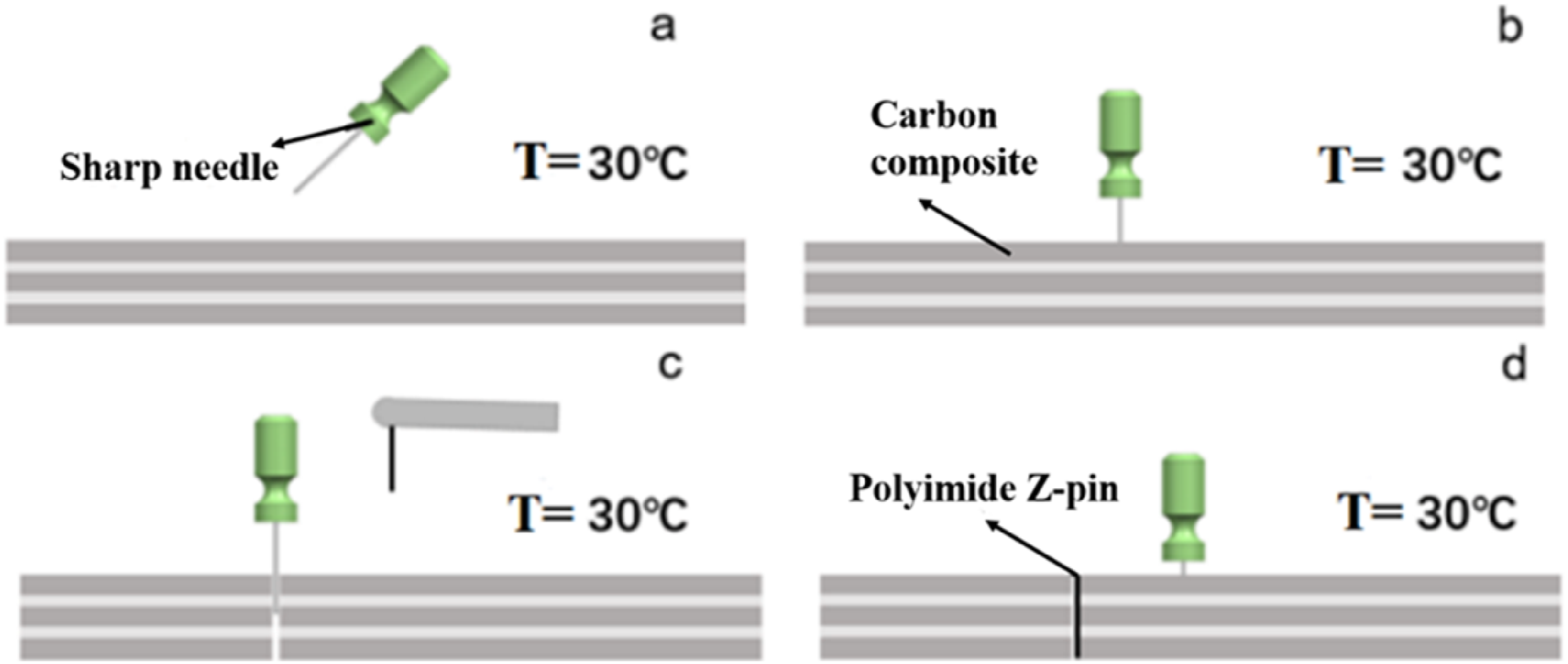
Test equipment and experimental process
As shown in Figure 6, the flexural experiments were conducted on the DNS 300 electronic universal testing machine in accordance with the ASTM D7136/7136M standard. The test machine was loaded at the speed of 1 mm/min in one direction. Once the loading dropped by more than 30%, the loading process was stopped. The recording device was used to capture videos and take pictures during the test. The flexural experiment scene.
Results and discussion
Initial damage analysis
Characterization of initial damages
Previous studies23–25 have shown that implanted z-pins will result to many initial damages in eye-like zone, including fiber waviness, fiber fracture, fiber crimp, resin-rich area, and z-pin inclination. These damages will degenerate the intralaminar property of laminates. Chang
29
et al. found that tensile and flexural properties of z-pinned laminates decreased by 7%–10% on average with the help of UAZ process. Generally, the uncured laminates have not been softened by heating in UAZ process, before the z-pins are implanted into specimens. All laminates are too hard to allow the z-pin in easily. Thus, when z-pins are implanted by compulsion, some fibers around the z-pin are removed and squeezed to both sides. As a result, the fiber waviness and fiber crimp come into being, and few fibers under the z-pin are fractured. Based on this, an eye-like void zone has been created. Finally, the eye-like void zone is filled with the resin, resulting to forming the resin-rich area during curing. However, the resin-rich zone without unidirectional continuous fibers will induce fibers dilution and make the laminates weakness, as detailed in Figure 7(a)–(c). (a) The picture of eye-like zone and fiber waviness. (b) The picture of fiber fracture. (c) The picture of fiber crimp.
11

Some studies have shown that the length of eye-like zone 2L and the fiber waviness angle Schematic diagram of eye-like zone.
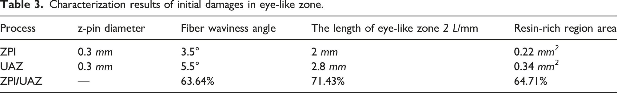
In view of z-pinned specimens fabricated by ZPI and UAZ process, we measure and microscopically examine the eye-like zone for z-pinned laminates. The quantifiable differences of initial damages caused by ZPI and UAZ process are reported in Figure 9(a) and (b). It can be seen that ZPI process causes fewer initial damages in the eye-like zone. Specifically, as detailed in Table 3, the fiber waviness angle caused by ZPI process is only 63.64% of that caused by UAZ process, the length of eye-like zone caused by ZPI process is only 71.43% of that caused by UAZ process, and the resin-rich region area caused by ZPI process is only 64.71% of that caused by UAZ process. (a). Statistical result of length 2L. (b). Statistical result of angle Characterization results of initial damages in eye-like zone.
The uncured laminates have been softened by heating in ZPI process, before the z-pins are inserted into laminates. Usually, the surface temperature of laminates is kept at 30 ± 5°C. At present, it’s easy to change the position of fibers in laminates. The sharp needle takes the contiguous and unidirectional fibers apart and pushed them onto both sides ingeniously, which results to local little fiber fracture and fiber crimp. Afterward, the sharp needle is returned and the z-pin is implanted into the prefabricated hole. Meanwhile, the fibers which have fluctuated in position begin to rebound until they come into contact with the nearby z-pin, which results to local little fiber waviness. However, the uncured laminates have not been softened by heating in UAZ process, before the z-pins are implanted into specimens. All laminates are too hard to allow the z-pin in easily, and the z-pin crushes and breaks the contiguous and unidirectional fibers roughly. Unfortunately, the fibers which have fluctuated in position cannot begin to rebound. As a result, massive fiber fracture, fiber waviness, and fiber crimp come into being, as detailed in Figures 10 and 11. The schematic diagram of differences between the ZPI and UAZ. The picture of differences between the ZPI and UAZ.

Z-pin inclination
Z-pins cannot be implanted vertically along the laminates’ thickness direction. A small angle between the z-pin and contiguous laminates through thickness direction is usually created. The statistical study
30
about UAZ process shows that the median angle of z-pin inclination is 14°, corresponding to z-pins with a diameter of 0.28 mm. While, with the assistance of ZPI process, the z-pin inclination only occurs in the curing stage. Meanwhile, with the aid of automatic z-pin inserted machine, z-pins can be implanted as vertically as possible along the laminates’ thickness direction. As detailed in Figure 12, the median angle of z-pin inclination is 5.5°, corresponding to z-pins with a diameter of 0.3 mm. Compare with that of UAZ process, the z-pin inclination angle is reduced by approximately 60%. Z-pin inclination angle frequency histogram in ZPI process.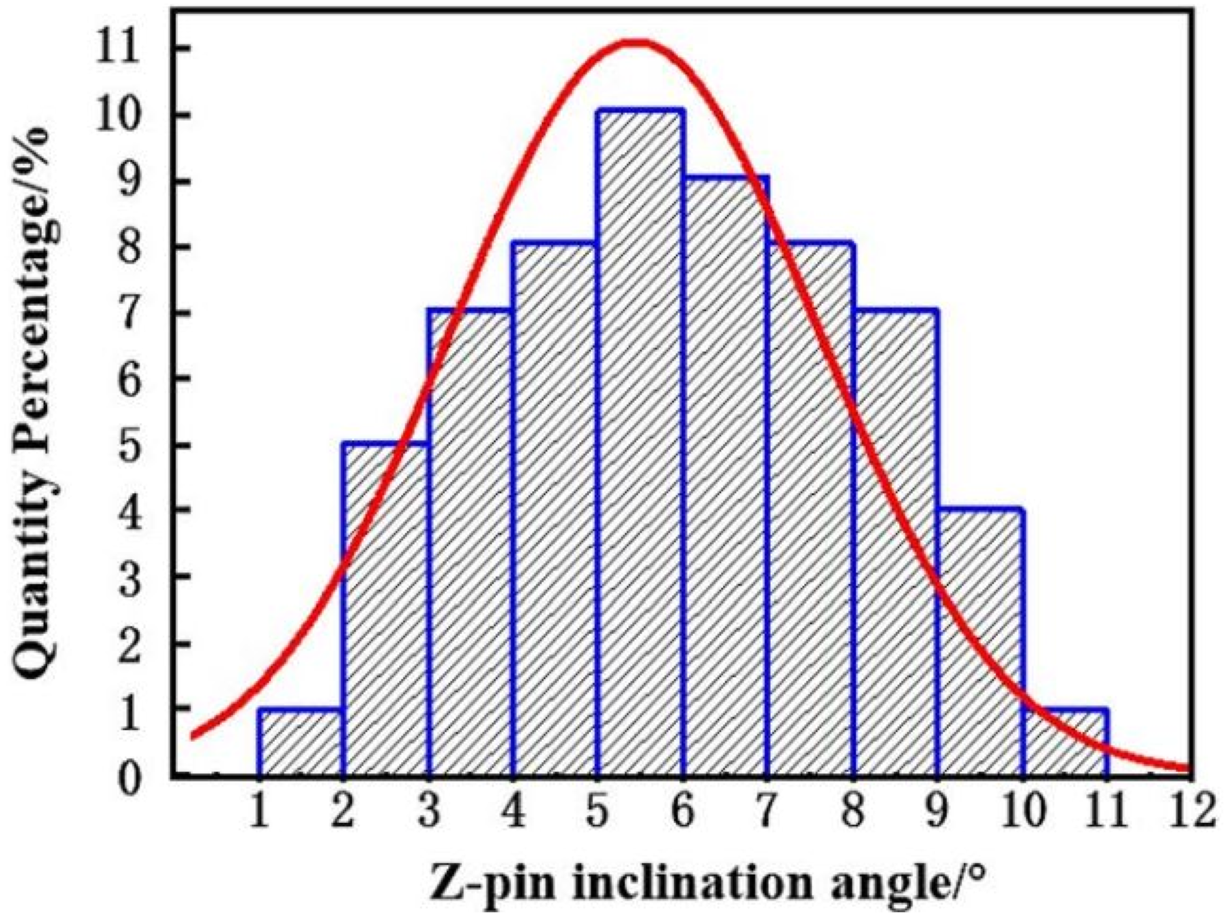
Loading-displacement curve
All specimens show almost linear elastic behavior before the peak loading. There are some differences between unpinned specimens and z-pinned specimens after reaching to peak loading. Specifically, for unpinned specimens, the loading dropped abruptly without any yielding phenomenon. Whereas, for z-pinned specimens, the loading decreases step by step, which means that they occur yielding phenomenon, as detailed in Figure 13. In engineering, although most composite material structures exhibit brittle failure characteristics (the loading-displacement curve before failure remains dropped linearly). While, z-pinned specimens exhibit quasi-brittle failure characteristics (the loading-displacement curve after failure remains dropped nonlinearly). Loading-displacement curves of all specimens.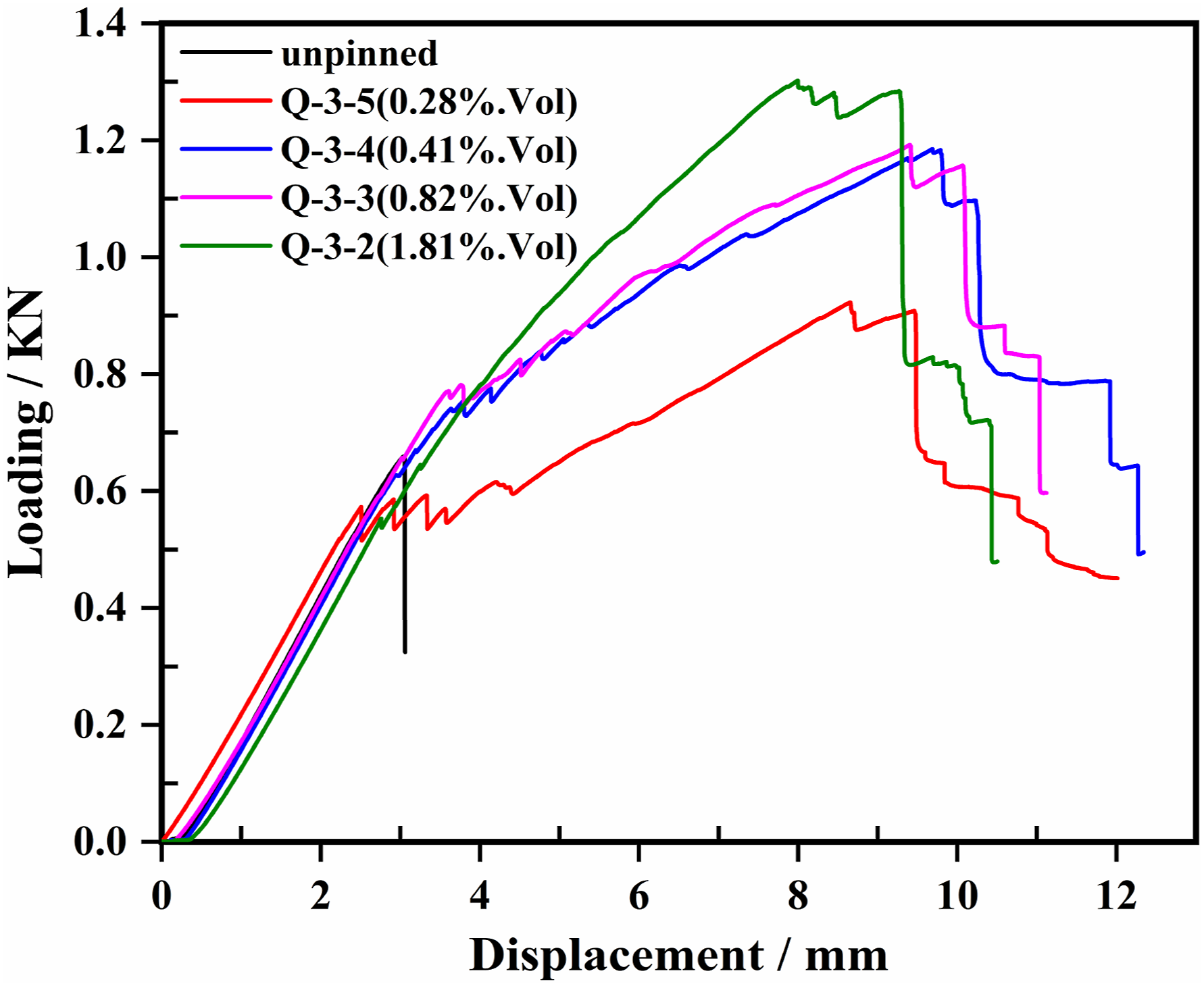
Moreover, it’s interesting to observe failure mode of all specimens during loading.
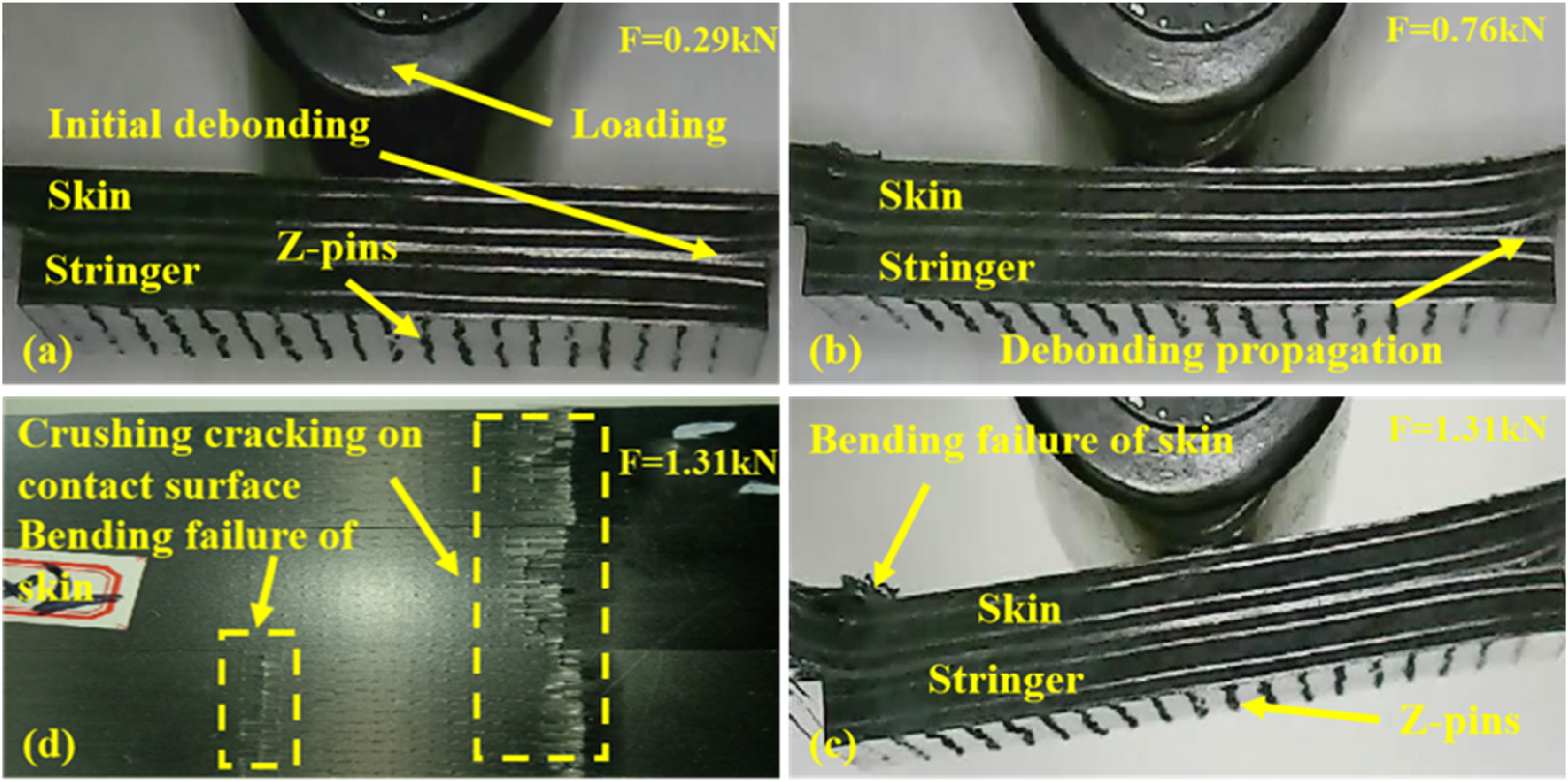
From the perspective of macro failure of specimens, for unpinned specimens, the initial debonding between the skin and the stringer could be observed after loading to 0.24 kN. They continue to be loaded to 0.42 kN, and the initial debonding cracks extend from the left verge of stringer to the center of that. Meanwhile, the initial debonding could be observed at the left verge of stringer. The ultimate debonding of the skin could be discovered after loading to 0.68 kN. So many crushing cracks on the contact surface of failed specimens could be found, as detailed in Figure 14(a)–(d). In contrast, for z-pinned specimens (0.3 mm and 1.81%), the initial debonding between the skin and the stringer could be observed after loading to 0.29 kN. Extraordinarily, when specimens continue to be loaded to 0.76 kN and 1.31 kN, the initial debonding cracks do develop very slowly. There is little debonding of the skin, until z-pinned specimens failed. A few crushing cracks on the contact surface and a little flexural failure of failed specimens could be found, as detailed in Figure 15(a)–(d). All z-pinned specimens exhibit the same failure modes but in different degree. The failure mode of the unpinned specimen. (a) The initial debonding cracks. (b) The delamination and debonding. (c) The extensive debonding. (d) The cracking on the contact surface. The failure mode of the z-pinned specimen (0.3 mm and 1.81%). (a) The initial debonding cracks. (b) The little debonding. (c) The cracking on the contact surface. (d) The flexural failure of skin.
Another observation is the mesoscopic failure mode of z-pinned specimens. The observed object includes reinforced fibers, matrix resins, and z-pins. All z-pinned specimens exhibit the same failure modes but in different degree. These modes include: (1) the fiber breakage and split, inter-fiber debonding, and breakage; (2) the matrix cracking; (3) delamination; and (4) the z-pin pull out and deformation, as detailed in Figure 16(a)–(c). In summary, the z-pin changes the mechanical behavior of the specimen under flexural loading and makes it being the quasi-brittle material. In addition, the z-pin could prevent the specimen from the skin delamination, and stop the debonding between the skin and the stringer developing extensively. (a) The failure mode of the fibers. (b) The failure mode of the matrix. (c) The failure mode of the z-pin and laminates.
Effect of z-pin density
Firstly, we take the effect of z-pin density into account. We collect the peak loading of specimens with different z-pin density, as detailed in Figure 17(a). Meantime, taking conservation of energy into account, the total energy absorption of specimens is defined that the total area is enclosed by loading-displacement curve. We collect the energy absorption of specimens with different z-pin density, as detailed in Figure 17(b). There is no doubt that z-pins play an extremely important role in enhancing connection strength and preventing debonding of the specimen. Specifically, compared with unpinned specimens, the peak loading of z-pinned specimens is increased by about 98% at maximum. Amazingly, the energy absorption is increased by about 9 times at maximum. With the increase of z-pin density, the peak loading and energy absorption of z-pinned specimens do not increase continuously. Moreover, before the certain threshold, the peak loading and energy absorption increase quickly. After that, they increase or decrease slowly. We could explain the above phenomenon by analyzing the toughening mechanism of z-pins. (a) The peak loading of specimens with different z-pin density. (b) The energy absorption of specimens with different z-pin density.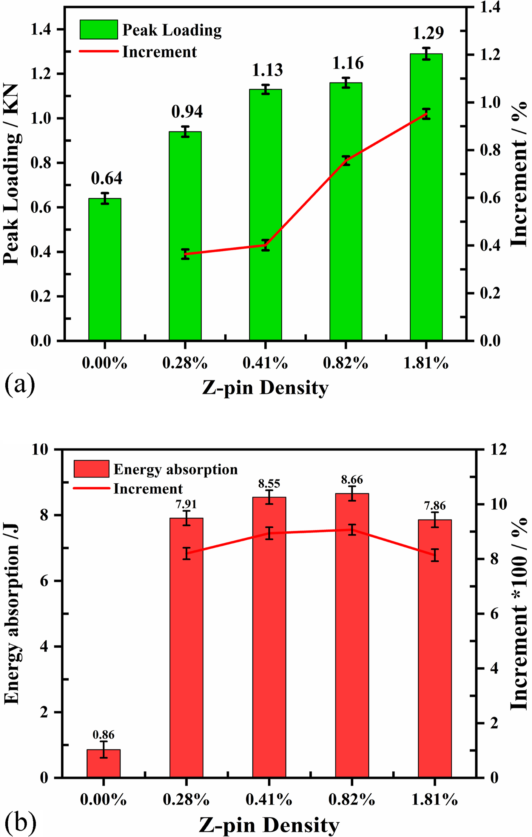
Under the flexural loading, the toughening mechanism of z-pins could be summarized to three stages along the direction of debonding cracks forward, as detailed in Figure 18(a)–(c). Firstly, the linear elastic deformation stage of the specimen: after the stress of the skin-stringer interface reaches the strength limit, the initial debonding cracks come into being at one verge of the stringer, and its tip develops to the near column z-pins, as shown in Figure 18(a). Secondly, the z-pin elastic bridging stage: the cracking tip crosses to the next column of z-pins, and the debonding area enlarges rapidly. The deformed z-pins generate bridging force at the cracking trailing edge, which results to the flexural loading increase significantly, as shown in Figure 18(b). Thirdly, the z-pin is pulled out and fractured stage: At the crack trailing edge, some z-pins are pulled out frictionally or fractured due to shear stress, which results to the inter-fiber debonding or fractured of z-pins. Therefore, the flexural loading gradually decreases step by step, as shown in Figure 18(c). Interestingly, the shear force not only makes z-pins deformed but also makes them squeeze the near resin, resulting in the pressure (Fn) increasing. This phenomenon is known as “snubbing effect,”
31
as detailed in Figure 19(a). The “snubbing effect” leads to the steep increasing of the shear stress, which could make the inter-fiber of z-pins debonding and splitting, and make z-pins being fractured, as detailed in Figure 19(b). Because of the augmentation of the Fn, it is difficult to make the z-pin pull-out, which makes the z-pin bridging force increasing prominently. Schematic diagram of z-pinned mechanism. (a) The initial debonding cracks. (b) The little deformed z-pins. (c) The pulled out and fractured z-pin. (a) The picture of Snubbing effect. (b) The failure mode of the z-pin.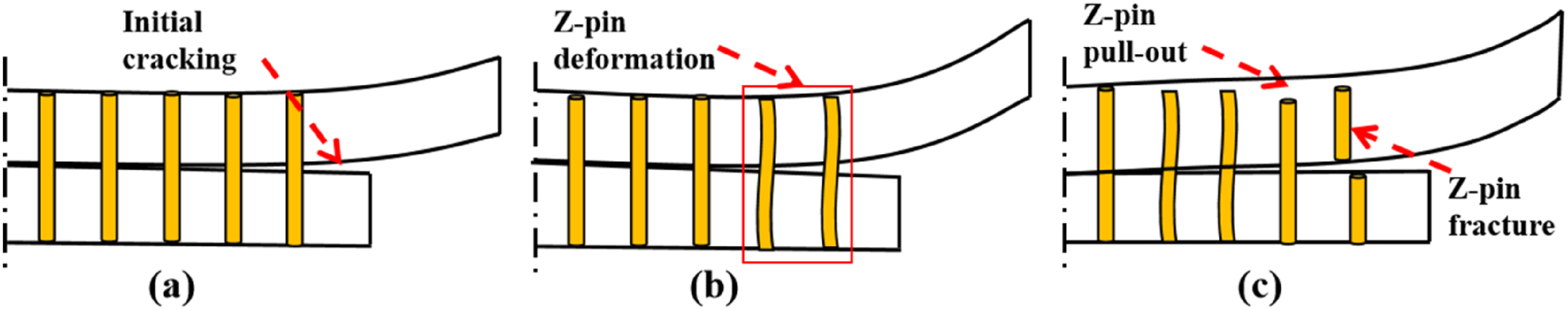

Based on experimental observation during testing, the peak loading of z-pinned specimens before the large-scale crack opening and z-pin pull-out occurs. Besides, at this stage, Park
32
et al. suggests that the z-pin elastic bridging stage is dominant and responsible for increasing peak loading of specimens. The elastic stress arises from interfacial shear traction between the z-pin and adherend. The elastic bridging force generated by z-pins due to interfacial shear traction is expressed as: The failure mechanism of debonding cracking.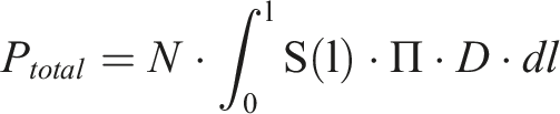

Nevertheless, it is found that penetrating cracks appeared between the opposite and adjacent z-pins in specimens with the high z-pin density (0.3 mm and 1.81%), as detailed in Figure 21(a). These penetrating cracks are not generated during the curing process. Under the flexural loading, the stress concentration is prone to occur at the initial damage zone, which could induce the initiation of the cracking. Penetrating cracks stem from the development of these initial cracks. Penetrating cracks will degrade the mechanical properties of z-pinned specimens. In order to solve this problem, it is necessary to set the arrangement of z-pins reasonably, avoiding the use of z-pins in each column and each row in parallel. It is beneficial to make the adjacent z-pins staggered and form a long distance between the two. For example, all z-pins are distributed in a hexagonal array instead of quadrilateral array, as detailed in Figure 21(b). Otherwise, the initial damages will also degrade the intralaminar property due to excess z-pins inserted. In a word, the z-pin density plays an essential and complicated part in preventing skin-stringer from debonding, excessively high or low density isn’t desirable. (a) The picture of penetrating cracks. (b) The arrangement of the z-pins.
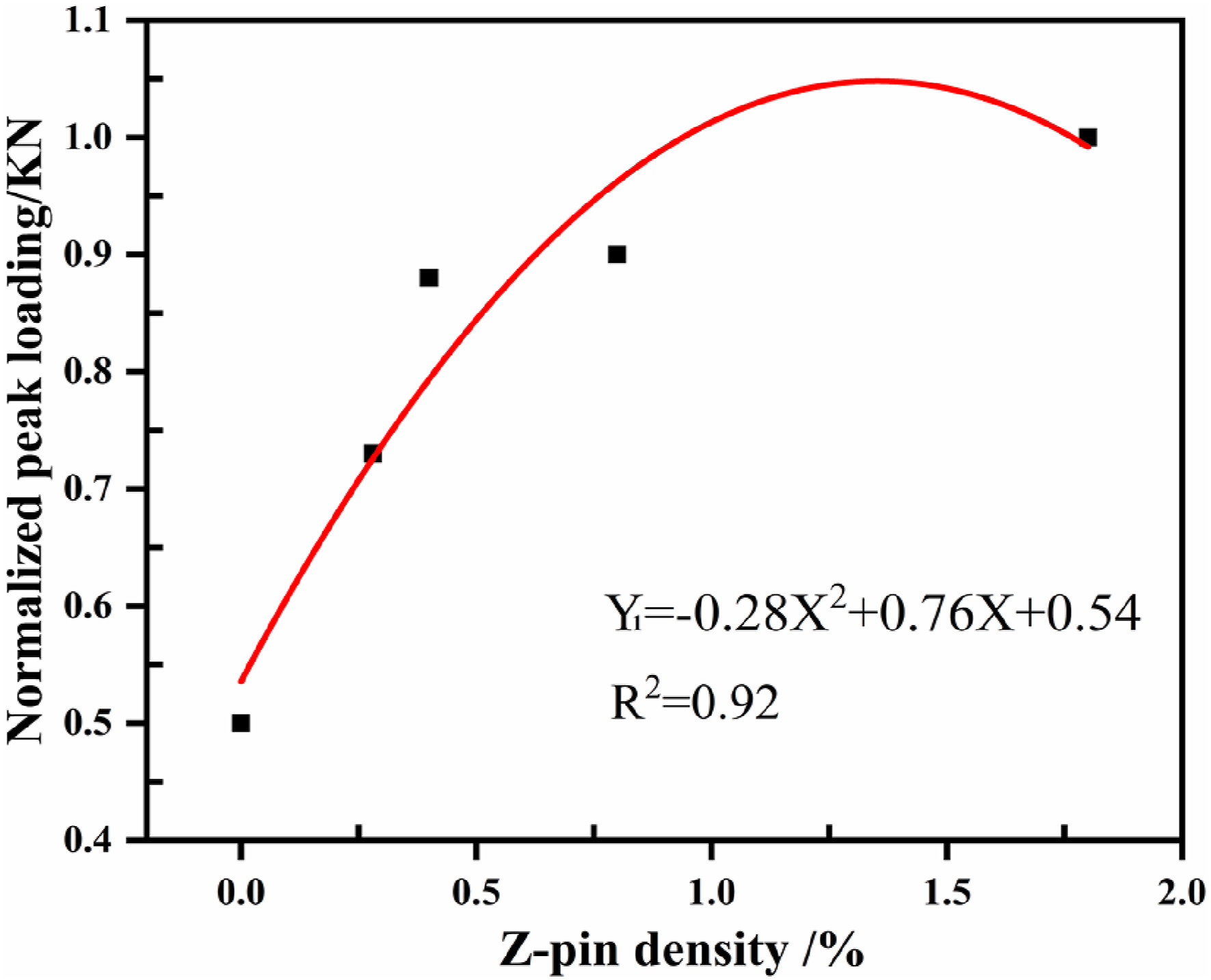
It is observed that the peak loading shows a regular variation with z-pin density, while the variation of energy absorption with z-pin density is not obvious. In order to further investigate the mathematical relationship between the z-pin density and peak loading, regression analysis has been performed within the parameters of this test. The results are shown in Figure 22. Meantime, we find that the optimal z-pin density is 1.35% within a certain range. The relationship between z-pin density and peak loading.

Effect of z-pin diameter
Furthermore, it’s worthy of paying attention to the effect of z-pin diameter, as detailed in Figure 23(a)–(c). Compared with unpinned specimens, the peak loading and energy absorption of z-pinned specimens with thin z-pins have been increased by 98.44% and 8 times, respectively, while that of z-pinned specimens with thick z-pins has been increased by 76.56% and 7.5 times, respectively. In a word, thin z-pins are beneficial to improve the peak loading and energy absorption. (a) Loading-displacement curves of specimens with different z-pin diameter. (b) The peak loading of specimens with different z-pin diameter. (c) The energy absorption of specimens with different z-pin diameter.
The literature
32
indicates that changing the z-pin diameter mean to changing the contact area between z-pins and laminates with a fixed z-pin density. When thin z-pins are used, assuming the z-pin length is the same and z-pin density is fixed, the contact area between z-pins and laminates is more than that of thick z-pins, as detailed in Figure 24 and Table 4. Accordingly, mechanical properties of z-pinned specimens are directly related to the total contact area between z-pins and laminates. The larger contact area provides better resistance to pull-out of z-pins, which leads to more energy absorption and larger peak loading. Calculation of the total bonding area. The calculated total contact area of z-pins.

Conclusion
In this paper, the flexural performances of simplified skin/stringer composite structure with different z-pin densities and diameters have been investigated experimentally. The quantifiable differences of initial damages caused by ZPI and UAZ process have been evaluated precisely. And the relationship between z-pin parameters (z-pin density and z-pin diameter) and flexural performances has been explored by comparative analysis. In addition, the damage mechanism of z-pinned specimens under flexural loading has been revealed briefly. The detailed conclusions are summarized as followings: (1) The specimen reinforced by polyimide z-pins presents the superior mechanical behavior compared with unpinned ones. The peak loading is increased by 98% at maximum, and the energy absorption is increased by 9 times at maximum. Parameterized research indicates that the optimal z-pin density is 1.35%. Besides, thin z-pins are beneficial to improve the peak loading and energy absorption, which attributes to more total contact area of z-pins. (2) The sharp needle takes the contiguous and unidirectional fibers apart and pushed them onto both sides ingeniously, but crushes and breaks the contiguous and unidirectional fibers roughly. Therefore, the ZPI process can significantly reduce initial damages of z-pinned specimens compared with UAZ process. The z-pin inclination angle is decreased by 60%, and the initial damages in eye-like zone are significantly reduced. (3) The z-pin makes the specimen exhibit the quasi-brittle behavior under flexural loading. Thus, z-pins cause the additional energy absorption of specimens by playing a bridging role, which makes the debonding propagation stable and the peak loading significantly increased. In addition, the “snubbing effect” will enhance the bridging effect of z-pins, but it will lead to inter-fibers debonding, splitting, and shear failure of z-pins.
Footnotes
Declaration of conflicting interests
The author(s) declared no potential conflicts of interest with respect to the research, authorship, and/or publication of this article.
Funding
The author(s) received no financial support for the research, authorship, and/or publication of this article.
CRediT authorship contribution statement
Bin Yan: Writing—original draft, validation, and formal analysis. ShengWei Zhu and Yuan Li: Writing—review and editing and supervision. LiangJi Shen and YunKe Zhang: Project administration, methodology, and conceptualization. WenTao Jiang: Visualization and supervision. Hu Dou and WenLi Kang: Validation and methodology.
Data availability statement
Data will be made available on request.