
Abstract
Digital image correlation (DIC) is a powerful technique for determining material deformation and damage and currently is viewed as a potential method to study failure and crack propagation in advanced composite materials. Case studies in concrete, epoxy adhesives, and carbon/epoxy laminates demonstrate the effectiveness of the DIC technique in visualizing crack propagation. This review highlights the applications, challenges, and implementation of the DIC technique in the failure and crack propagation of fibre-reinforced polymer (FRP) composites. The important factors such as field of view, speckle pattern, and algorithm choice are discussed while emphasizing the need for careful selection and calibration. The review concludes by highlighting the significance of crack propagation studies for composite behaviour and the role of DIC in calibrating and validating models of composite failure analysis. Future research directions include investigating mixed-mode delamination, improving calibration procedures, assessing DIC accuracy for large deformations, and comparing different DIC algorithms, which are discussed.
Keywords
Introduction
Fibre-reinforced polymer (FRP) composite materials have been one of the greatest alternatives to metallic counterparts in structural design for various industrial applications in recent decades due to their lightweight characteristics, high strength, high stiffness, energy absorption capability, and flexibility in manufacturing a wide range of components. Polymer composites have found several applications in the aerospace, automobile, railway, and naval construction industries. FRP composites can, however, also experience crack propagation, which can result in disastrous failure. To create materials and structures that are more damage-resistant, it is crucial to understand the mechanisms of crack propagation in FRP composites. 1
The phenomena of failure, visually represented as crack initiation and propagation, occur when a material undergoes stress, leading to fracture and the directional spread of cracks. This is a significant and widespread problem in many engineering applications where various composite applications are targeted.2–4 Crack propagation in FRP composites is a complex process influenced by a variety of elements such as fibre type, fibre volume percentage, matrix material, loading conditions, and the presence of defects. In FRP composites, crack propagation can occur in various modes: (1) opening mode (mode I), where the crack opens due to perpendicular loading to the crack plane; (2) sliding mode (mode II), where stress and applied load are parallel to crack surfaces; and (3) mixed-mode I/II, where a combination of loads in Modes I and II is applied, leading to crack propagation induced by normal and shear stresses. 5 Debonding of fibres from the matrix often initiates all modes of fracture propagation and form fibre-bridging phenomena. 6 Once a crack has begun, it can spread by fibre pull-out or matrix cracking. Fibre pull-out happens when the fibres are yanked out of the matrix as the crack progresses. When the matrix material fails in tension, matrix cracking develops. The sliding of fibres relative to each other often initiates mode II crack propagation. Once a crack has begun, it can spread through either fibre sliding or matrix shearing. When the fibres slide past each other as the crack propagates, this is known as fibre sliding. When the matrix material fails in shear, this is referred to as matrix shearing. 7 The study of crack propagation is essential for understanding the behaviour of materials under different loading conditions. Accurately detecting and measuring crack propagation is critical for ensuring the safety and reliability of structures and components. 8
Traditional methods such as optical microscopy, scanning electron microscopy, and X-ray tomography have been used in the past to study crack propagation. Measurement of crack propagation in composite materials can be accomplished using a variety of techniques.
9
Among the most common approaches are: • Measurement of crack length: This method involves measuring the length of the crack as it propagates. This can be accomplished through the use of several techniques such as scanning electron microscopy,10–12 ultrasonic testing,13–15 and radiography.16–18 • Measurement of crack opening displacement (COD): This method includes measuring the displacement between two spots on the material’s surface ahead of the fracture tip. This can be accomplished through the use of several techniques such as scanning electron microscopy,10–12 strain gauges,10,19,20 and DIC.19–21 • Crack tip opening displacement (CTOD) measurement: Similar to COD testing, but more sensitive to minor changes in crack tip displacement. CTOD can be measured using a variety of techniques, including scanning electron microscopy,22–24 strain gauges,25–27 and DIC.28–32 • Energy release rate (ERR) measurement: This method determines how much energy is required to propagate the crack. ERR can be measured using a variety of ways, including the J-integral method14,33–37 and the virtual crack closure technique (VCCT).38–41
Each of the strategies outlined above has benefits and drawbacks. Fracture length measurement is a simple and uncomplicated approach, although measuring the fracture length precisely can be problematic, especially in small cracks.
However, these methods have limitations such as low resolution, lack of accuracy, and high cost. Optical microscopy uses light to magnify and examine the microstructure of materials. It is a non-destructive and relatively inexpensive method but has low resolution and cannot be used to study crack propagation in real-time.
42
Scanning electron microscopy (SEM) uses a focused electron beam to examine the microstructure of materials. It has a higher resolution than optical microscopy but is time-consuming and costly.
43
X-ray tomography uses X-rays to produce a 3D image of the microstructure of materials. It provides high-resolution images but is expensive, requires specialized equipment, and is not suitable for large-size structures44–47 [6]–[9]. Although COD and CTOD measurements are more sensitive to minor changes in crack tip displacement than crack length measurements, they are more difficult to execute. ERR measurement is the most sensitive way of crack propagation measurement, but it is also the most complicated to execute. The optimal approach for evaluating damage evolution and fracture process in composite materials will be determined by several parameters, including the size of the crack, material attributes, and desired accuracy. In general, crack length measurement is appropriate for large cracks, whereas COD, CTOD, and ERR measurements are appropriate for minor fractures. The desired precision will also influence the approach selection. The crack length measurement method is the least accurate, whereas the ERR measurement method is the most precise.
9
Other competitors of the DIC technique for crack propagation include: • High-speed photography: This technique entails taking a series of high-speed photographs of the fracture as it spreads. This can be used to trace the progress of the crack and to calculate the rate of crack growth.48–50 • Acoustic emission (AE) monitoring: This method includes measuring the acoustic emissions produced by the crack as it propagates. AE-based NDT can detect fibre fractures, fatigue cracks, interface debonding matrix microcracks, as well as delamination. This can be used to monitor the location and progression of the crack.33,51–54 • Magnetic particle testing (MT): In this approach, a magnetic field is applied to the material, and cracks that disturb the field are then looked for. However, the probability of this method to detect small cracks under 2.5 mm was only 50%.
55
This can be used to discover fissures that are not evident on the magnetic material’s surface.
56
• Liquid penetrant testing (LPT) is applying a liquid penetrant to the material and then checking for cracks that trap the penetrant under ultraviolet or white light.
57
This can be used to discover fissures that are not evident on the material’s surface.58,59
Each of these approaches has advantages and disadvantages. The optimum method for measuring crack propagation will be determined by several parameters, including the size of the crack, material qualities, and desired accuracy. Furthermore, a traditional method such as strain gauges is simple to use but only limited to measure consistent strain in a specific location. Furthermore, the location of the crack must be determined before the experiment begins. DIC technique can measure the strain anywhere on the specimen surface as long as it is within the region of interest (ROI).
DIC is a powerful technique that has been used to study crack propagation in a wide range of materials and loading conditions. DIC technique has become a popular method for studying crack propagation due to its spatially detailed imaging capability, which can provide detailed information about the deformation of the material and the formation and propagation of cracks.60,61 As shown in Figure 1, the publications involving the DIC method have exponentially increased over the last decades, even in the fields where there used to be less usage of DIC techniques previously.62–64 However, the usage of the DIC method in monitoring crack propagation which found its importance in the past few years was considered an important topic to be reviewed. Therefore, this review paper aims to provide an inclusive overview of the existing literature based on scientific papers, conference papers, and some book chapters regarding crack propagation studies of FRP composite materials and structures using the DIC technique and will be focused mostly on FRP composite materials. Number of articles involving typical strain measurement techniques during the past from 2000 to 2015.
62

Crack propagation
Crack propagation is the process by which a crack in a material grows over time, often leading to material failure. Crack propagation can occur due to a variety of factors, including mechanical stress, thermal stress, and environmental factors such as corrosion.65,66 Understanding crack propagation is important for developing reliable and durable materials, as well as for predicting and preventing material failure. Cracks can occur at various scales, ranging from microcracks to mesocracks and macrocracks as depicted in Figure 2. Length range of different types of cracks.
67

Mesocracks are typically between 0.1 mm and several millimetres in size and are often visible to the naked eye. They may be caused by external forces or internal defects, such as inclusions or voids, and degrade material properties. Mesocracks can have a significant impact on the mechanical properties of composites, including their strength and stiffness. 68 Mesocracks can be studied using a variety of techniques. Shang et al. investigate internal microcracks of recycled aggregate concrete (RAC) by using X-ray CT scanning. 69 Despite the good results obtained, the paper also stated that the method is not suitable for large-scale analysis due to its low efficiency. Understanding the formation and propagation of mesocracks is important for predicting the overall durability and lifespan of a material.
Microcracks, on the other hand, are much smaller cracks that are typically less than 100 microns in size. These cracks are often not visible to the naked eye and are difficult to detect. Some researchers detect microcracks by using a moisture/freeze/dry cycle with the help of a microscope which takes a lot of time. 70 Microcracks can form due to a variety of factors, including thermal stresses, chemical reactions, and fatigue loading.70–72 Understanding the behaviour of microcracks is important for predicting the long-term reliability of materials in a range of applications, from aerospace to biomedical engineering.
Macrocracks are the largest and most severe type of crack, typically on the order of centimetres to metres in size, and can completely fracture the material. They may be caused by a sudden and severe impact, excessive loading, or material defects. Macrocracks can significantly compromise the structural integrity and may require repair or replacement of the affected component.
In composite materials, researchers often focused on microcracks. 73 Composite materials are made up of multiple layers of fibres and resin, which can create interlaminar stress concentrations that can lead to the formation of microcracks. Microcracks in composite materials can lead to reduced strength and stiffness, as well as decreased fatigue life and fracture resistance.73,74 Additionally, microcracks in composite materials can propagate quickly and unpredictably, making them difficult to detect and control. Therefore, it is important to employ appropriate testing methods and design practices to minimize the formation and propagation of microcracks in composite materials.
Delamination
Crack propagation in composite materials can result in delamination, causing separation between layers or plies. This separation may lead to fibre breakage and delamination. 75 This delamination can cause degraded material properties, which can lead to further cracking and ultimately, catastrophic failure. Delamination is a major concern in many industries, including aerospace, automotive, construction materials, and energy applications, because it can significantly reduce the strength and stiffness of a material or structure and can ultimately lead to catastrophic failure.76–79 Delamination is one of the most common failures in composites that could induce other types of damage such as matrix failure and compromising the structural integrity of composite structures, 79 which is why this paper only focused on delamination.
One reason why delamination is a main concern in the industry is because it is often difficult to detect and predict. Delamination can occur deep within a material or structure, making it difficult to detect with traditional inspection methods such as visual inspection or ultrasonic testing. This can lead to undetected delamination that can compromise the structural integrity of a component, resulting in costly repairs or even accidents. In addition, delamination is often influenced by a variety of factors such as temperature, humidity, and loading conditions, making it difficult to predict its behaviour and development over time.
To address these concerns, researchers and engineers are developing new methods for detecting and predicting delamination in materials and structures such as thermography, acoustic emission, and DIC which can provide valuable data on material surface deformation and damage that later could be used for internal failure analysis of composite structures. 61 Additionally, advanced computational methods such as finite element analysis and cohesive zone modelling can help to predict the behaviour of delamination under different loading conditions, allowing engineers to design more reliable and durable components.80,81 Russo et al. developed a numerical tool which can simulate composite’s delamination growth under fatigue load and found an excellent agreement with test results. 82 This method can be very helpful in determining fatigue behaviour in composite due to less time needed compared to conventional method. Russo et al. studied the fatigue response of CFRP based on Shokrieh and Lessard’s material properties and showed a good agreement between the two in term of material degradation.80,83 However, there are some crucial factors that need to be obtained an accurate result such as penalty shear stiffness, interface shear strength, mesh/element size, fracture toughness, and viscosity parameter.84–88 Some of these values need to be obtained from experimental test which means that experimental test still needs to be performed beforehand. Overall, understanding and addressing delamination is critical for ensuring the safety and reliability of materials and structures in a wide range of industries.
Fracture mechanics involves the study of how cracks propagate and ultimately lead to failure in materials under different types of loading such as mode I, mode II, mode III, and mixed-mode.
Mode I loading, also known as the opening mode or tensile mode, involves a crack opening under tensile stress perpendicular to the plane of the crack. This mode of loading is the most common and has been extensively studied in fracture mechanics. Examples of mode I loading are on laminated glass used in automotive windshields and architectural applications, and mode I delamination can occur when the glass layers separate due to impact or stress, compromising the integrity of the glass. Most researchers focused on mode I due to its simplicity compared to mode II or mixed-mode. 89
Mode II loading, also known as sliding mode or in-plane shear mode, involves a crack sliding along a plane under a shear stress parallel to the plane of the crack. Mode 2 loading is less common than mode 1 loading but is still important to consider in certain applications. Examples of mode 2 loading include the shear testing of adhesives and the opening of a crack in a thin sheet due to a bending load.
Mixed-mode I/II loading occurs when both mode I and mode II loading are present simultaneously. This can happen when a material is subjected to complex loading conditions or when a crack changes direction during propagation. Mixed-mode I/II loading is particularly important to study especially because delamination initiates and propagates due to the combination of tension and shear stress. 90 In addition, mixed-mode loading is often encountered in real-world engineering applications, such as in construction, marine, automotive, and aerospace industries where structural components are subjected to complex loading conditions.91–95
One of the most common mixed-mode I/II tests is the mixed-mode bending (MMB),
96
which was proposed by Reeders and Crews
97
and was further refined by Reeder for delamination toughness.
98
Figure 3 shows the combination of mode I double cantilever beam (DCB) and mode II end-notched flexure (ENF) which resulting to mixed-mode I/II MMB. MMB, as shown in Figure 4 is a type of loading that occurs when a material is subjected to a combination of in-plane shear and bending stresses. MMB has been extensively studied in the field of fracture mechanics, as it is an important mechanism for crack growth in many engineering structures. MMB from combination of mode I and mode II.
99
MMB test configuration.
100


MMB testing involves applying a bending load to a specimen, while simultaneously imposing a shear stress through the use of an external load or an angled grip. The angle of the grip and the bending load ratio are varied to produce different levels of mode mixites, which refers to the proportion of shear and bending stresses in the loading. The main advantage of MMB is its ability to simulate a wider range of loading conditions than other fracture toughness testing methods. Specifically, MMB can measure the fracture toughness of materials under a range of mixed-mode loading conditions that more accurately reflect the types of stresses that the material is likely to experience in real-world applications. To compare the results of the MMB test, a failure criterion is needed. Sourissau et al. combined MMB with optical fibre in which greatly improved the analysis.
101
The equation of mode I and mode II energy release rates at any loading condition was provided by ASTM
102
:


Benzeggagh and Kenane developed a mixed-mode failure criterion.
103
The B-K criterion has been used by many researchers to improve the understanding of mixed-mode I/II delamination behaviour.
104
One of the main advantages of B-K criterion is the ability to evaluate mode II fracture toughness without having to conduct a mode II test. The B-K criterion was given by: η = least-square fitting parameter of interlaminar fracture toughness

Franklin and Cristopher
105
experimented to compare B-K criterion with the quadratic and cubic polynomial criterion which was given by:

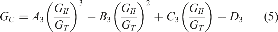
The B-K and polynomial criterion is suitable to be used with unidirectional MMB specimens while only the cubic polynomial criterion is suitable to be used for angle ply specimens. 105
Digital image correlation
The DIC is a full-field, contactless optical photogrammetry method that assesses the distribution of displacement across the measurement surface. According to Zhou et al., DIC is one of the main measurement methods used in photomechanics to measure the deformation. 106 Photomechanics is the study of structural behaviour using photonics techniques (optical methods) in experimental mechanics. Displacement variation is one physical quantity that can be measured non-destructively. The development of optical measurement techniques, information technology tools, computational power, improved knowledge of the physics relating to photonics, and increased awareness have all contributed to the field’s continued expansion in the nuclear, automotive, and aerospace industries.
When using the DIC method, the surface of the target specimen sprayed with a stochastic (random) speckle pattern, as shown in Figure 5, serves as the reference surface for the measurement. Through the motion tracking of the speckles, all the displacement and strain components during the testing process can be obtained. It enables precise strain measurements in two dimensions (2D) and three dimensions (3D). While 3D is primarily used for curved structures or when the out-of-plane deformation is significant, where the full-field data is needed, 2D image analysis is typically used for flat surfaces with small deflection. Furthermore, with the proper selection of camera resolution and checkboard size for calibration purposes, DIC can be applied over a wide range of testing surface areas. The strain data can be compared to the results of finite element (FE) simulations, which can be used to calibrate and validate material parameters and models. Example of speckle pattern.
107

The strain calculation process using DIC is described in sufficient detail in the literature.108–112 Generally, image processing begins with identifying the region of interest (ROI). The ROI is then subdivided into evenly spaced virtual grids called subsets. Each subset has its own variation of grey levels, which is caused by speckles sprayed on the surface of interest. An image is taken as a reference before any loading. The deformed images can be taken either continuously or step wise throughout the testing. The image analysis tool would identify the first subset of the reference image and examine the subset from the deformed image that has the same grey level. This is done through the correlation functions. The common ones are the zero-normalized cross-correlation (ZNCC) criterion and a zero-normalized squared sum of differences (ZNSSD) criterion. The image processing tool would track and compare each subset of the entire ROI using correlation functions. The subset with the greatest similarity will be chosen as the current position. The corresponding displacement is thus calculated by subtracting the centroids of the reference and deformed subsets in the x and y directions. The same procedure is followed for all ROI subsets until the full-field displacement distribution is obtained. Because the strain is very sensitive to noise, the displacement fields are smoothed using a strain window. The strain fields are then computed. Most commercial software provides users with the flexibility to select their preferred strain formulation theory.
Usage of DIC
In recent years, DIC has been increasingly applied to measure the displacement and strain in various types of materials and loading conditions. For example, DIC has been used to determine the coefficient of plastic anisotropy of aluminium 1050.
110
In addition, DIC has also demonstrated its suitability for use in composite materials. Gan et al.
113
proposed a modified Arcan fixture (MAF) that can be loaded with combined tension-shear, pure compression, or compression-shear loadings. The authors applied DIC to measure the full-field deformations of the E-glass/epoxy specimens. The results showed that DIC could provide the load response and failure behaviour of the composites. Feito et al. combined the usage of DIC with infrared thermographic (IRT) for notched CFRP in which the method successfully determined the failure mode for each experiment.
114
Subsequently, Laux et al.
115
employed DIC to determine the displacements of the open-hole carbon/epoxy specimens loaded under combined tension-shear and compression-shear using the same MAF. Several laminates were tested by the authors to investigate the effects of ply thicknesses and fibre orientation on failure behaviour using a novel DIC-based methodology. 3D-DIC was proposed as a method for analysing and comparing composite materials reinforced with four different fillers, which was dicalcium silicate, magnesium silicate, tricalcium silicate, and wollastonite.
116
Furthermore, DIC has also been used to characterize mechanical properties at the micro level. Depuydt et al.
117
proposed a new method for single fibre tensile test (SFTT) through direct strain measurement using DIC. The applicability of this method has been successfully demonstrated by the authors for steel, flax, and bamboo fibres. The method has the advantage of reducing the number of specimens and errors caused by fibre slippage. With the integration of a high-speed camera, DIC has proven its ability to record displacement and strain at high strain rates. For example, Cui et al.
118
investigated the influence of strain rate and fibre orientation on the in-plane shear response of the HexPly IM7/8552 carbon/epoxy composite. Tension and compression tests were carried out on [+/−45 ͦ ]4s laminates at the rates of 0.01 mm/s (quasi-static), 11 m/s (tensile), and 5 m/s (compression). Additionally, the 8552 epoxies were also tested at 0.001 mm/s, 0.1 mm/s, and 3–8 m/s. Even a study on stress relaxation on an edge crack, as shown in Figure 6, used DIC and was proven to be accurate.
119
DIC has been successfully used to investigate the effect of tabbing adhesive on the mechanical properties and failure mechanism of carbon fibre under tensile test.
120
For each test, a DIC system was used to measure the strain for the entire surface of the specimens. Strain field of specimen before and after stress relaxation by DIC.
119

The ability of DIC to measure the out-of-plane displacement of composite sandwich beams under quasi-static loading, low-velocity impact (3.7 m/s), and high-velocity impact (178–203 m/s) has also been demonstrated. 121 In addition, DIC has been used to locate the core cracking and front face-sheet failure of typical styrene acrylonitrile (SAN) foam E-glass fibre-reinforced polymer (GFRP) face-sheet sandwich panels when subjected to blast loading. 122 The best method for determining the displacement and strain of sandwich panels was highlighted, and the guidelines for interpreting the out-of-plane displacement and maximum principal strain data obtained from DIC in terms of damage and type of response were discussed. Moreover, DIC has also been applied in the field of biomechanical for bones and implants strain analysis. 123 Multiple cracking behaviours were observed when using DIC to characterize the tensile behaviour of textile-reinforced concrete (TRC) composites in civil engineering applications. 112 The displacement of road materials such as asphalt mixtures (HMA), stone, hydraulically stabilized soil, and geosynthetics has also been quantified using DIC. 108 The test identified the principal strains and their corresponding principal orientations. Furthermore, the authors emphasized the benefit of DIC in eliminating slippage issues in tensile test. Currently, DIC is getting consideration as a standardized testing method. The implementation of DIC, for instance, has been discussed in ASTM B 831-14, ASTM E 647, and ASTM D 807-17. 124 In order to solve a more difficult problem, Pan B., who reviews DIC, suggests combining DIC with modern design and simulation tools such as CAD and FEM.64,124
Due to the absence of standardized calibration process, researchers commonly validate DIC results by comparing them with data obtained from another method.64,125 Huo et al. validate the DIC-VCCT approach by performing fracture test of metallic joints first and compare the results with literatures as well as FEA and theoretical formulations.38,126 Golewski used the data obtained from MTS 810 press to validate the DIC system.127,128 Mehdikhani et al. combined DIC with X-ray computed tomography (CT) for fibre orientation characterization and validated the result with two established CT post-processing tools. 129 Some researchers on the other hand, combined the usage of DIC with finite element analysis (FEA) in order to validate the DIC measurements; however, it’s important to note that while these approaches provide valuable comparative insights, they may not constitute validation in the strictest sense, as they lack an absolute ground truth.130,131 Xu et al. validate the accuracy of DIC by numerical modelling of tensile test of the same specimen and found the same agreement between the two. 132 Zhu et al. validated the DIC result by comparing the crack length obtained by DIC with the crack length measured using optical microscopy for mode I fatigue. 133 Ibrahim et al. studied on the reliability of DIC by compared the DIC data with machine test deflection and found that the DIC was proved to be useful for crack mouth opening displacement of cementitious composite undergoing 3PB. 134
DIC method for crack propagation
The DIC technique process is as shown as in Figure 7 which makes it possible to identify the location in which the crack initiates and further propagates. Gonabadi et al.
135
have shown that DIC can detect interlaminar shear cracks, which can be used to suggest a failure criterion based on the maximum load. This can be used to accurately measure interlaminar shear strength of composite materials. Golewski used DIC for Mode II fracture of concrete and said that the usage of DIC is both economical and practical.
127
The crack propagation, which was not visible through the naked eye, was visible to the DIC. The rate dependency of 3M Scotch-Weld AF 163-2OST and 2216 B/1 grey epoxy adhesives bonded titanium alloy Ti-6Ql04 V has also been studied using DIC.
136
According to Reiner et al., it is possible to overcome partial translaminar damage such as delamination and matrix cracking by combining DIC strain fields with ultrasonic C-scans to calibrate DIC strain values.
137
The debonding behaviour of the adhesive joints was investigated under the mode I (opening test) at speed ranging from 0.05 mm/s to 3 m/s. Lima et al. combined DIC with optical backscatter reflectometry (OBR), which it shows that the method was useful for identifying crack propagation.
138
The analysis of DIC for crack propagation in fatigue fracture was also successfully performed for CFRP/Al adhesive joints in which fails due to adhesive failure and cohesive failure.
139
Taheed and Datla compared two different adhesives on CFRP in which the DIC was able to determine a tri-linear-separation law (TSL) for ductile adhesive joint and a bi-linear TSL for brittle adhesive joint.
140
This shows that DIC was able to be paired with FEA, by determining the separation law suitable for each specimen. Process of digital image correlation technique.
114

DIC is also implemented to characterize composites delamination damage. Cui et al.
141
used DIC for the measurement of the opening and shear separations of Z-pin reinforced IM7/8552 carbon/epoxy laminates during mode I and mode II delamination, respectively. The tests were carried out at speeds ranging from 0.01 mm/s to 12 m/s. Yasaee et al.
142
used the DIC system to determine the displacement and crack propagation in IM7/8552 carbon/epoxy composites (with and without Z-pin reinforcement) under mode II delamination via the end-notched flexure (ENF) test. The ENF test was conducted at three different loading rates ranges: quasi-static (8.3 × 10⁻⁶ m/s), intermediate (1–4 m/s), and high (5.5 m/s). Furthermore, Zhao et al. claimed that DIC could determine the plastic zone ahead of the crack tip, as shown in Figure 8.
143
Not only that, DIC has also been used to investigate the development of kink band under bending test.
144
However, the downside of using DIC for kinking failure was that the strain field become discontinuous between sections leading to non-uniform strains across the kink band width. DIC also was capable of detecting matrix cracks.145–151 Determination of plastic zone ahead of the crack tip by DIC.
143

Despite that, Pannier et al. did compare the result with µ-computed tomography (µCT) and found that there are some cracks that were not detected by DIC such as sub-surface cracks which indicate that DIC’s crack analysis was limited to only to surface crack.
151
Yudhanto et al. highlighted that DIC was only able to identify cracks developed in resin-rich regions in the specimen surface.
145
Zhong et al. employed DIC techniques to analyse the evolution of the surface strain field of CFRP undergoing cyclic loading and found that DIC was able to identify the failure of the composite including interlaminar shear cracks, fibre/resin interface debonding, fibre pull-out, and fibre buckling.
152
The DIC also was able to identify the crack propagation with each cycle, without the need for finite element analysis as shown in Figure 9. Feng et al. proposed to monitor mode II crack growth at the bi-material interface undergoing ENF and 4ENF using DIC.
153
In this experiment, it is difficult to capture pictures at high-crack growth rates due to unstable crack growth near the end, limiting the length of crack length captured by DIC to 94 mm. Poulton et al. used DIC for quantifying high strains along misaligned fibre, detecting onset of damage and identifying macroscopic damage within web-flange junctions of pultruded GFRP bridge decking.
154
The DIC data shows a good agreement with strain gauges and revealed that the strains along misaligned fibre/resin interfaces were shear dominated. Esmaeili et al. employed DIC for E-glass undergoing mixed-mode I/II and used the obtained stress intensity factor for a novelty fracture criterion based on maximum energy release rate and maximum tangential stress to predict the direction of small kink growth.
155
An element-removal (ER) global-DIC method was proposed for accurate deformation measurement of surface discontinuities by Chen et al. in which the method aims to progressively eliminate elements along the discontinuity whilst increasing the tracking accuracy in its vicinity.
156
The ER-global-DIC method is validated using synthetic analytical and FE-based DIC experiments, then it was shown that the proposed method significantly improve accuracy in determining displacement fields near the crack vicinity compared to regular local and global DIC techniques. This method will be useful in applications where crack deflections are expected as the method will be able to register much more data points in the displacement fields of the near crack region. A DIC study by Irven et al. was found to reveal microstructural damage such as matrix cracking and cross-ply laminate failure of diglycidyl ether of bisphenol-A (DGEBA).
157
According to Irven et al., the use of DIC was found to be a powerful tool for understanding fibre-matrix interactions in composite laminates. Crack propagation in tensile-tensile fatigue during cyclic loading.
152

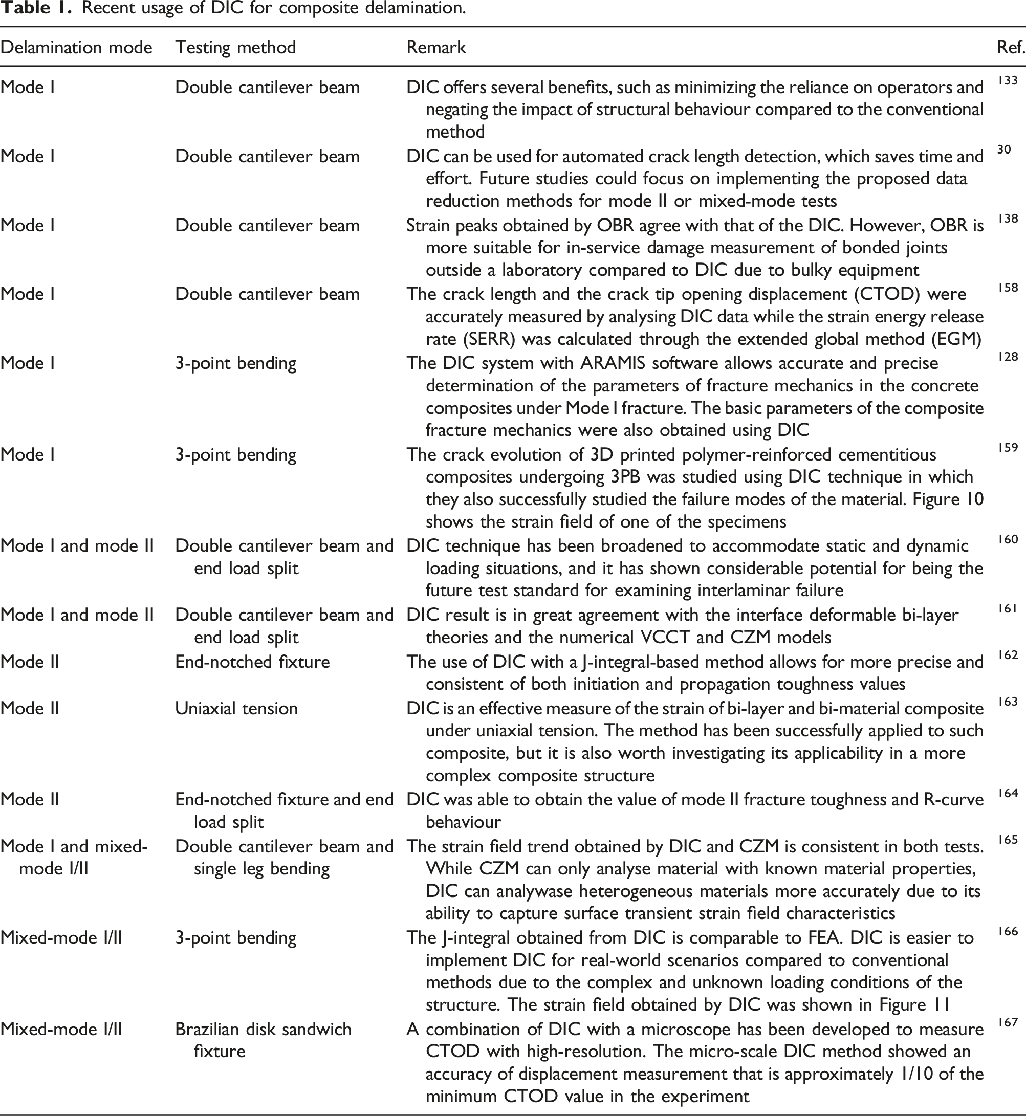
Recent usage of DIC for composite delamination.

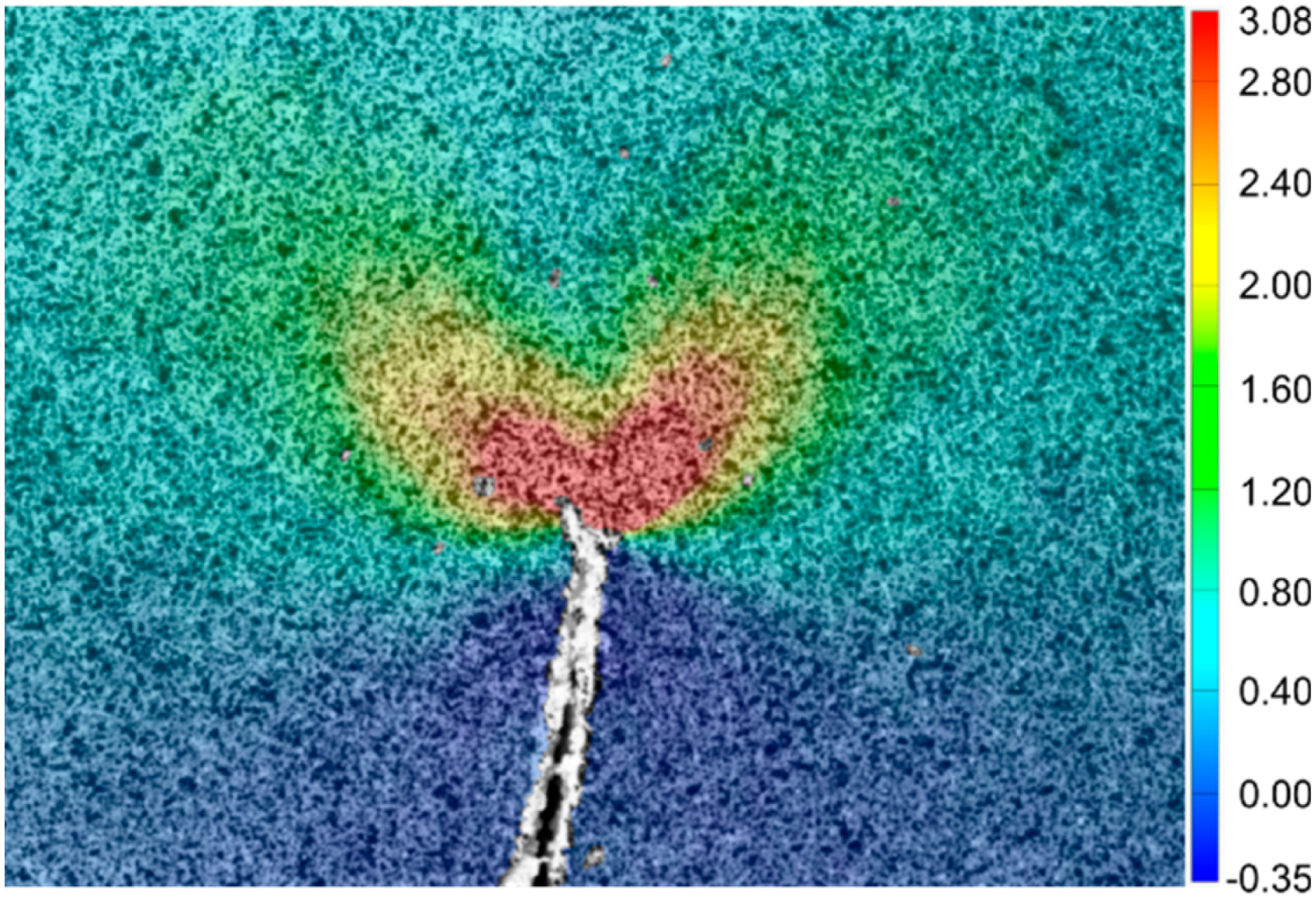
Strain field obtained by DIC for specimen undergoing 3-point bending. 159
Strain field obtained by DIC around the crack tip for specimen undergoing inclined edge-cracked semicircular bend. 166
Factors of DIC technique measurement
While the usage of DIC keeps increasing, some important parameters need to be considered when using DIC for crack propagation of composite material such as field of view, speckle pattern, and algorithm choice.
168
Field of view is a crucial consideration when using DIC for testing composite materials. The field of view refers to the area of the specimen that is captured by the imaging equipment and used for correlation analysis. In composite testing, the field of view must be large enough to capture the entire region of interest where deformation or damage is likely to occur. This is particularly important for composites, which can exhibit complex deformation patterns and failure mechanisms that may occur over a large area. High-resolution characterization, however, has a restricted depth of focus due to the small field of view, making it difficult when the specimen moves closer or further from the camera, in which information loss on material behaviour may occur, leading to inaccurate or incomplete results.
169
In some cases, the testing rig needs to be modified to provide a suitable field of view for the DIC system such as during stamp forming, as shown in Figure 12.
170
Composite deformation at micro-scale has been performed with micro-scale DIC (μDIC) with the preferable to use 2D-DIC rather than 3D-DIC due to the need for high-resolution magnification. A larger field of view allows for the observation of a broader region during deformation. However, a larger field of view may sacrifice the ability to capture localized deformations with high precision. Researchers need to carefully select the field of view based on the specific deformation characteristics they aim to study, balancing the need for an overall view with the requirement for localized detail. Therefore, it is essential to carefully select the appropriate imaging equipment and adjust the field of view to ensure that all relevant deformation and failure mechanisms are captured. Modified hemispherical testing jig.
170

Spatial resolution is another crucial factor to consider when using digital image correlation (DIC) for measuring crack propagation in composite materials. Spatial resolution refers to the level of detail or granularity in the images captured by the DIC system, and it plays a significant role in the accuracy and precision of the deformation measurements. High spatial resolution allows for the detection and tracking of smaller features, enabling the analysis of fine-scale deformations, cracks, or damage in composite materials. On the other hand, low spatial resolution may result in the loss of important details, leading to less accurate measurements and potentially missing critical information about crack initiation and propagation. When selecting imaging equipment for DIC measurements, researchers need to consider the spatial resolution capability of the cameras and lenses used. Higher spatial resolution is especially important when studying micro-scale deformations or when there is a need for detailed analysis of small regions within the composite material. One fundamental trade-off in DIC measurements lies in the choice between spatial resolution and measurement noise. Increasing spatial resolution enhances the ability to capture fine details of deformation and crack propagation, providing a more understanding of the material’s behaviour. However, this comes at the expense of increased sensitivity to measurement noise. The spatial resolution is influenced by the size of the subset or interrogation window used for correlation analysis. Smaller subsets allow for higher spatial resolution but may be more susceptible to noise, while larger subsets provide a smoother response at the cost of spatial detail. Speckle pattern refers to the random distribution of reflective markers on the surface of the material being tested. While larger speckles offer robustness, they may struggle to capture subtle deformations, whereas smaller speckles enhance sensitivity but may introduce noise. This trade-off requires researchers to carefully calibrate the speckle size to align with the scale of deformations they aim to investigate. Ogierman and Kokot investigate on the differences made by different speckle sizes and found that the accuracy of DIC decreases slightly with increasing speckle size.
171
However, Reu et al. observed that the loss of spatial resolution can be reduced by increasing subset size or speckle size.
172
According to Yaofeng and Pang,
173
the optimal subset size lies in between systematic errors and random errors. Zhou et al. did research on DIC speckle pattern as shown in Figure 13 and found that Pattern 1 was better because it was well distributed with appropriate speckle sizes.
174
The pattern should be dense enough to provide enough data points for the algorithm to accurately track the deformation of the material. At the same time, the pattern should be uniform and not too dense to prevent oversaturation of the camera, which can lead to errors in the measurements.62,175 When DIC is used to study significant strain behaviour, such as in-plane shear, localized stress concentrations, or high strain rates, there is a risk of paint cracking and flaking as typical spray paints are typically reliable for up to 20% strain.168,170,176 Some suggested that the paint will be more resistant to cracking when it is being tested while still slightly damp.
169
Therefore, selecting an appropriate speckle pattern and paint type that provides a balance between density and uniformity is crucial for obtaining accurate and reliable DIC measurements in composite materials testing. Example of different speckle sizes and randomness.
174

The algorithm is also a critical consideration when using the DIC method. The choice of algorithm affects the accuracy and reliability of the strain measurements obtained. Several algorithms have been developed for the DIC method, and each has its strengths and limitations. There is commercial software that includes algorithms along with supports such as GOM Correlate, 177 VIC-2D, 178 VIC-3D, 179 and Strain-Master, 180 while there is also open-source software such as ALDIC, 181 NCORR, 182 iCorrVision-2D, 183 and iCorrVision-3D. 184 It is important to consider the computational efficiency of the chosen algorithm, as some algorithms can be computationally intensive and may require high-performance computing resources. Proper selection of the DIC algorithm can improve the accuracy and reliability of the results, providing valuable insights into the behaviour of composite materials under various loading conditions. When deformation occurs, the speckle will move from their initial positions due to deformation, post-processing techniques become crucial for accurate DIC measurements. Adjusting the subset size in post-processing allows for better tracking of the deforming speckles. 185 Smaller subset sizes can capture finer details but may be more susceptible to noise, while larger subset sizes may smooth out small deformations. During the analysis, the algorithm plays the most important role. Advanced pattern-matching algorithms in DIC software can enhance the robustness of the correlation process, enabling accurate tracking of deforming speckles and minimizing errors. 186
Limitation of digital image correlation
Digital image correlation (DIC) has proven to be a powerful and versatile technique for measuring deformations and strains in materials but the method still has some limitations influencing the accuracy and reliability of the results. Understanding these limitations is crucial in order to employ DIC in fracture mechanics studies. A speckle pattern on the material’s surface is required for DIC. DIC relies on tracking the movement of unique features or markers in the speckle pattern. When it comes to crack propagation, the visibility of cracks within the speckle pattern becomes a critical factor. This speckle pattern can be achieved by various methods, such as spray painting the surface with fine powder, creating a random pattern of dots with a laser, applying stickers or decals with unique patterns, or using microspheres or particles suspended in a transparent coating. The choice of method depends on factors like the desired speckle size, the material’s characteristics, and the specific goals of the experiment. Pan et al. proposed an indicator called mean intensity gradient to assess the quality of speckle pattern used in DIC. 187 The DIC technique excels at capturing continuous deformations, but the precise moment when a crack initiates can be elusive. Small precursor cracks may not be discernible in the speckle pattern, making it difficult to identify the exact point of crack initiation. While high spatial resolution is essential for capturing fine details, it comes with a trade-off. Increasing spatial resolution leads to larger data sets and higher computational demands. This can be a challenge when dealing with crack propagation studies, particularly in real-time or in-field applications which mostly contain discontinuous deformation. 188 However, the said challenges can be overcome by upgrading hardware setups or changing the algorithm to motion magnification (PMM) technique. 189 The quality of DIC measurements is heavily dependent on lighting conditions. In crack propagation scenarios, changes in lighting due to crack opening or changes in surface geometry can introduce variations in the speckle pattern, potentially leading to errors in displacement tracking. Juno et al. found that the accuracy of DIC was reduced when non-ideal lighting conditions were applied. 190 In some applications, DIC can be difficult to use. It can be challenging, for example, to utilize DIC to assess crack propagation in materials that are subjected to high temperatures, moving complex geometries, and very thick specimens.191–195 While DIC is a valuable tool for deformation analysis, researchers and practitioners should be aware of its limitations when applied to crack propagation studies. Combining DIC with complementary techniques and interpreting results judiciously in consideration of these limitations will enhance the accuracy and reliability of fracture mechanics analyses. Blug et al. studied on the usage of real-time DIC for fatigue crack growth behaviour. 196 However, the method requires the usage of GPU-based DIC system in order to achieve a faster computational speed.
Conclusion
In conclusion, the study of crack propagation is essential for understanding the behaviour of materials under different loading conditions, and the use of the DIC technique has proven to be an effective method for studying crack propagation in a wide range of materials. The DIC method offers spatially detailed imaging capability, which can provide detailed information about the deformation of the material and the formation and propagation of cracks. The exponential increase in the use of DIC study in crack propagation research over the last few decades indicates its significance in the field. Crack propagation can occur at various scales, and the understanding of mesocracks and microcracks is important for predicting the overall durability and lifespan of a material. The formation of microcracks in composite materials is a particular concern due to the presence of multiple layers of fibres and resin, and the use of appropriate testing methods and design practices such as MMB is necessary to minimize the formation and propagation of microcracks. The development of optical measurement methods, computational power, and the enhancement of the understanding of photonics has led to the continuous growth of this field. The strain data obtained from the DIC approach can be used to calibrate and validate material parameters and models, making it an indispensable tool for researchers and engineers. Finally, the study of delamination in composite materials is crucial for developing reliable and durable composite materials. The use of the DIC technique can provide valuable information on delamination, which can aid in the development of composite materials with increased fatigue life and fracture resistance.
Future research
The following topics are some of the challenging topics for future research based on the current studies: • Mixed-mode I/II delamination should be focused on the development of a new composite structure because it generally exhibits real-world loading conditions. • The accuracy and reliability of DIC measurements depend heavily on the calibration procedure. Standardization of calibration procedures could improve the reproducibility and reliability of DIC results. • Less attention has been paid to the usage of DIC with mixed-mode delamination, mainly with MMB which has become a standard in ASTM. Moreover, the high-speed camera of the DIC device has the capability to perform high-displacement rate MMB tests. Furthermore, this test will assess the accuracy of the DIC method for large deformation which was rarely focused on. • It will be interesting to see the difference between each DIC algorithm software along with its result based on the same photography.
Footnotes
Acknowledgements
The authors highly acknowledge the Universiti Teknologi Malaysia and the Ministry of Education Malaysia for the financial support to implement the research through the UTMFR grant, Q.J130000.3851.21H92, and FRGS grant, R.J130000.7851.5F517. In addition, the authors acknowledge financial support from Universität der Bundeswehr München to cover the APC of the journal for the publication process.
Declaration of conflicting interests
The author(s) declared no potential conflicts of interest with respect to the research, authorship, and/or publication of this article.
Funding
The author(s) disclosed receipt of the following financial support for the research, authorship, and/or publication of this article: The authors highly acknowledge the Universiti Teknologi Malaysia and the Ministry of Education Malaysia for the financial support to implement the research through the UTMFR grant, Q.J130000.3851.21H92, and FRGS grant, R.J130000.7851.5F517. The authors acknowledge financial support from Universität der Bundeswehr München to cover the APC of the journal for the publication process.