
Abstract
As the use of more sustainable natural fibres and bio-based resins in fibre reinforced polymers (FRPs) becomes more widespread, their susceptibility to damage due to explosive detonation needs to be evaluated. In this paper, flax and jute FRP panels were blast tested and compared to equivalent mass glass FRP panels. Comparisons were made between flax and glass FRPs manufactured using a synthetic Prime 20 epoxy and a Super Sap epoxy resin containing bio-based raw materials. The transient measurements revealed that all the FRPs exhibited high-peak displacements and viscously damped elastic vibrations. The results showed the predominance of fibre strength and stiffness, and the lesser influence of resin system. The presented modified non-dimensional analysis approach could be extended to predict peak displacement of FRPs during blast events in the future. The failure mode progression for each panel type was identified, providing unique and detailed insights for designers and blast protection engineers. The work should prove valuable to blast protection engineers considering the effects of explosive detonations on structures containing FRPs.
Keywords
Introduction
Fibre reinforced polymers (FRPs) are often employed in mass-critical structural applications (such as car bodies and aircraft, for example). They are versatile materials with properties that can be tuned by carefully designing the fibre orientations and thicknesses. Many are based on synthetic fibres (usually carbon 1 or glass 2 ) and resins (such as epoxy, polyester and PEEK). These can withstand high temperatures without significant degradation and have good corrosion properties, and high-specific strength and stiffness. The higher strength and stiffness are attributed to the dominance of the fibre properties. 3 Recent work on FRPs incorporating higher strength fibres, such as S2-glass/phenolic FRPs 4 and Dyneema HB26 (ultra-high molecular weight polyethylene), 5 have shown their potential for use in defence applications requiring blast and/or ballistic resistance.
The unparalleled threat from climate change is driving society towards using more ‘eco-friendly’ sustainable alternatives. A reduced dependence on fossil fuels, lower disposal energy consumption and a generally lower harmful impact on human health and the environment are among the listed advantages.6–7 The definition of ‘sustainable’ varies, but two common approaches for FRP composites are (i) to use resins formulated with renewable resources such as plant oils8–10 and (ii) to use natural fibre reinforcements.6,7,9–11
Bio-based resins (resins formulated from biomass sources such as plants) are perceived as environmental friendlier options than their petroleum-based counterparts. The manufacturer of one such commercial resin, Entropy Resin’s ‘Super Sap’, claims that 29% of its carbon content comes from renewable plant sources. 12 An environmental impact analysis of Super Sap shows significantly less environmental impact compared to the industry average of petroleum-based equivalent resins. Reductions of 11–16% were noted across impact categories including human health, energy demand, climate change and water usage. 12
Natural fibre reinforced polymers (NFRPs) contain fibres derived from natural sources including plants, animals and agricultural waste. They were traditionally limited to applications where structural rigidity and strength were of secondary importance, as their tensile and impact strengths are much lower than glass fibre reinforced polymers (GFRPs). There have also been concerns about the effects of relative humidity on mechanical performance.7,13 However, there have been recent improvements in NFRP tensile moduli 9 and a new interest in developing treatments to overcome the challenges of these materials.6,13 This trend suggests that, in the future, NFRPs could be used in high-performance applications. They offer other advantages, such as cost effectiveness, availability and low density. 14 Rahman 7 adds vibrational damping as a key benefit to this list.
At present, environmentally friendlier NFRPs are being increasingly produced for the construction sector,7,9 textiles13,15 and the transportation industry. 16 Flax fibres are most often employed in the textile industry 15 and are widely used.13,17 Moudood 18 identified flax fibres as having potential in sports and transportation applications when there is a requirement to be eco-friendly. The low density compared to glass fibre makes flax reinforcement for FRPs attractive for mass sensitive applications. Similar to flax, jute fibres are considered more environmental friendly.16,19 They are the most commonly used natural fibre reinforcement 16 with over 2,300,000 tons produced globally. 17 Woven jute fabrics have a fine texture and good fire resistance, providing a widespread range of applications. 16 Aly-Hassan 19 proposed potential applications for jute including thermal and acoustic barrier walls in interior construction, furniture and electronic equipment housings. Yan et al. 13 proposed that hemp, flax and jute are the natural fibres with the most potential, and identified flax as the leading contender.
The public remains aware of the grave threat from explosions because of a variety of public incidents that caused devastating loss of life, enormous structural damage, and threatened economic and political stability.20–24 Blast protection systems are typically manufactured from materials of high strength and/or energy absorption (such as high-strength steels, rolled homogenous armour, and in some cases, synthetic fibre reinforced polymers). However, many other materials are used in construction, even though they are not good for blast protection, as explosion resistance is not seen as a critical issue. While there is a reasonable amount of data on the response of metallic structures and traditional (synthetic) FRP composites to blast loading,25–27 there is very little on the behaviour of NFRP composites or plant-based epoxy resins when exposed to air-blast loading. As the usage of sustainable constituent materials increases, due to environmental concerns, a gap exists in our understanding regarding their response to air-blast loading.
In general, damage caused by blast loading on fibre reinforced composites, particularly those reinforced with glass or carbon fibre, would be delamination, fibre fracture, matrix cracking and penetration or shearing at the boundary. The initiation, progression and extent of these failure types are influenced by explosive charge mass, stand-off distance, fibre type, specimen dimensions and clamping arrangement among others.25–27 Franz et al. 28 investigated the response of chopped strand mat glass fibre reinforced polyester composites with differing areal densities and test lay-up configurations, to localised blast loading. The resistance to matrix cracking was found to improve with areal density. Furthermore, layered composites had better blast resistant properties compared to monolithic composite plates. 28
Comtois et al. 29 found that the stand-off distance influenced the extent of damage as it was related to the imparting impulse and pressures. The clamping arrangement was found to have a significant influence on the damage pattern and failure. 29
Despite the superior tensile strength and modulus of the carbon FRPs, Tekalur et al. 30 found that the blast resistant properties were better for glass fibre reinforced vinyl ester composites than for carbon fibre vinyl ester composites. Similar conclusions were drawn with regards to the glass FRPs having a superior blast resistant ability to carbon FRPs by Yahya et al. 31 for poly-ether-imide thermoplastic composites under a uniform blast load. While more literature is available on the blast behaviour of synthetic fibre reinforced composites, further research is still necessary to fully understand the behaviour as there are a range of fibre types and arrangements.
Quasi-static and low-speed impact testing of NFRPs is frequently reported, for example, Refs. 6,32–34. NFRPs are strain-rate sensitive materials, meaning that their mechanical properties and failure mechanisms vary with strain rate. Khieng et al. 3 attributes this strain-rate sensitivity to the viscoelastic nature of their matrices, suggesting that viscous drag and frictional energy loss within NFRPs create complexity under different rates of strain. Wang et al. 32 performed uniaxial tensile tests on flax FRP using a high-speed hydraulic testing machine. A similar method was used by Fotouh 35 to characterise hemp fibre reinforced high-density polyethylene, where large scatter was evident in the results. Wang et al. 32 used a Weibull analysis to overcome scatter in their data to show that tensile strength, energy absorption and failure strain increased at strain rates exceeding 79 s-1. However, the force-time histories show evidence of inertia effects that are known to influence stress–strain curves obtained at higher loading rates using hydraulic testing machines. 36 Split Hopkinson pressure bar (SHPB) testing, usually performed in compression (for example, Hu et al. 37 ), is also considered unsuitable for characterising FRPs according to Parry et al. 36
For a recent review of strain rate properties of NFRPs, including many studies using SHPB methods, the reader is directed to Khieng et al. 3 In summary, dynamic mechanical property enhancement of NFRPs depends upon the fibre type (for example, flax, jute and hemp), test arrangement and loading type (compression, flexure and tension). Impact strength is known to be affected by the same factors as quasi-static tensile strength, 6 but how this translates to very high strain rates (103 to 104 s-1) is not apparent. This field is still immature and requires further development to facilitate accurate modelling development for NFRP behaviour at higher strain rates. It is not yet known whether the quasi-static mechanical properties are good predictors of the behaviour of these materials under blast conditions, where strain rates are exceptionally high (of the order of 103 s-1) and the loads are intense (high pressures and shocks, low durations and possible thermal effects depending on the stand-off distance).
This paper reports experimental results on the transient response and failure of NRFP panels subjected to air-blast loading. The blast response of jute and flax FRPs is studied and compared to that of GFRP panels of equivalent mass. The influence of substituting the Super Sap epoxy resin in the place of a traditional synthetic epoxy was also studied for a glass FRP and a flax FRP system. The paper provides a unique experimental validation dataset for the modelling community attempting to predict the transient behaviour of FRPs under intense, high strain-rate blast loads. The paper is experimental in nature and its findings are relevant to those modelling and assessing structural response or injury risk due to explosive events in settings where NFRPs are commonly used, even if they would not be the primary recommended materials for blast protection applications.
Materials and manufacturing
Fibre reinforcement
Glass, flax and jute fibre systems were chosen for this study because of their compatibility with epoxy resin systems, their suitability for vacuum infusion, their relatively low cost and their availability in South Africa at the time of testing.
Glass fibres
A 400 g/m2 plain weave glass fibre system was employed. The fibre was pre-treated with silane. 38 In previous blast studies,39–41 the same fibre system was combined with the Prime 20LV resin system, making them an ideal benchmark.
Flax fibres
550 g/m2, 2x2 twill weave, flax fibres were pre-treated using the LINEO© patented sizing technology. 42 Ideally, the NFRPs would have the same weave pattern and areal density as the glass FRP benchmark. The 400 g/m2 plain weave glass fibre is a standard product used in South Africa and unfortunately it was not possible to obtain plain woven natural FRP equivalents. Consequently, the 2x2 twill weave was considered the next most appropriate weave pattern as it was similar to fabric used in studies by Chouw and co-workers.24–32
Jute fibres
400 g/m2, 2x2 twill weave, jute fibre fabric was used to match the glass system areal density. The jute fibres did not have further surface treatments; however, the manufacturer claimed that processing could be carried out in the same way as standard glass fibre materials. 43
Resins
Prime 20 LV epoxy resin is a low viscosity synthetic (petroleum-based) epoxy resin that is suitable for use in resin infusion manufacturing processes. 44 When used with a slow hardener, it is suitable for the manufacture of large parts or thick sections, having low exothermic characteristics (an important consideration in NFRP laminates where the fibres are sensitive to elevated temperatures). Entropy Resin’s Super Sap CLR is also a low viscosity epoxy resin suitable for infusion and the manufacture of large structures. 45
Manufacturing
Panels for blast testing and material characterisation experiments were manufactured from the constituent materials using the Vacuum Infusion (VI) technique. The manufactured panels were cut into smaller panels and post-cured according to Refs. 44 and 46. For both resins, the ramp rate for increasing and decreasing temperature was 1°C/minute. Once at temperature, the Super Sap panels were kept at 80°C for 6 h, while the Prime 20 panels were kept at 50°C for 16 h. Further room temperature post-curing for 7 days was carried out for the Super Sap resin panels. Once post-curing was completed, the panels were inspected for visual defects such as large cracks or dry spots of fabric. Defective parts were discarded. The blast test and material characterisation specimens were then cut from the panels, at least 50 mm away from the free edges of the large panels and 20 mm away from any other edges (to ensure thickness consistency).
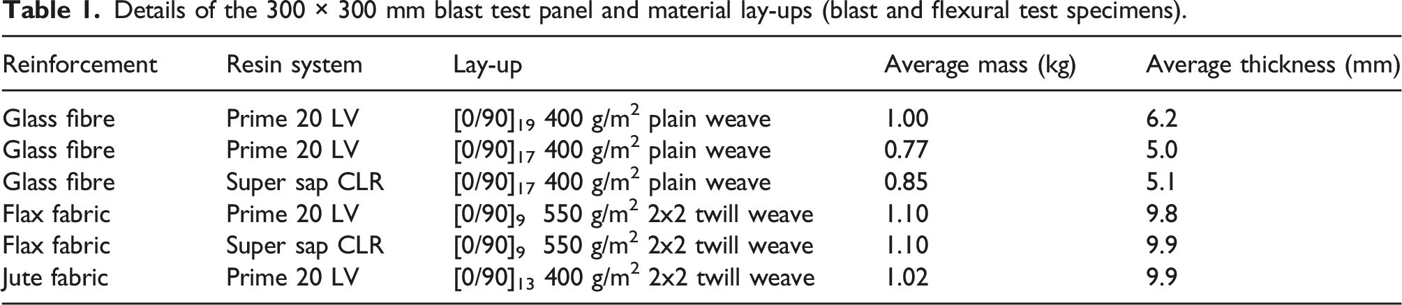
Details of the 300 × 300 mm blast test panel and material lay-ups (blast and flexural test specimens).
Double Cantilever Beam (DCB) bending tests were performed to characterise the interlaminar fracture toughness of the FRPs. According to Broughton, 47 it is the most commonly used test technique for measuring the initiation and propagation of Mode I fracture energy under quasi-static conditions. The DCB specimens were made separately from the main batch of panels as the specimens were manufactured with an initial crack within the FRP lay-up.
The same VI process was used, but with a layer of non-perforated release film placed in mid-plane section of the panel to create a crack in the material. Specimens were water-jet cut from the manufactured and post-cured panels using the dimensions based on ASTM D5528 48 standards. Loading blocks were bonded using Spabond 340 epoxy (with fast hardener) at one end. The jig assembly was placed in an oven for a post-curing cycle to cure the Spabond (35°C for 2.5 h). The jig was then removed and the post-curing cycle was completed for the post-curing of the infused resin system (50°C for 16 h).
Material properties
Flexural properties
Quasi-static 3-point flexural tests were performed, in accordance with ASTM 7264 49 on rectangular strips at a constant cross-head speed of 3 mm/min. As the thickness of the flexural specimens varied, shown in Table 1, the width and span were varied to maintain a width:thickness ratio of 13:4 and a span:thickness ratio of 16:1. At least five specimens per material type were tested.
The GFRP specimens failed on the compression side, with surface buckling and delamination under the central loading point. The NFRP specimens exhibited cracks on the tensile side under the loading point that spanned the width of the flax specimens and propagated through the thickness to the neutral axis. In the jute specimens, brittle through-thickness cracking was observed, followed by complete fracture of the specimen into two pieces.
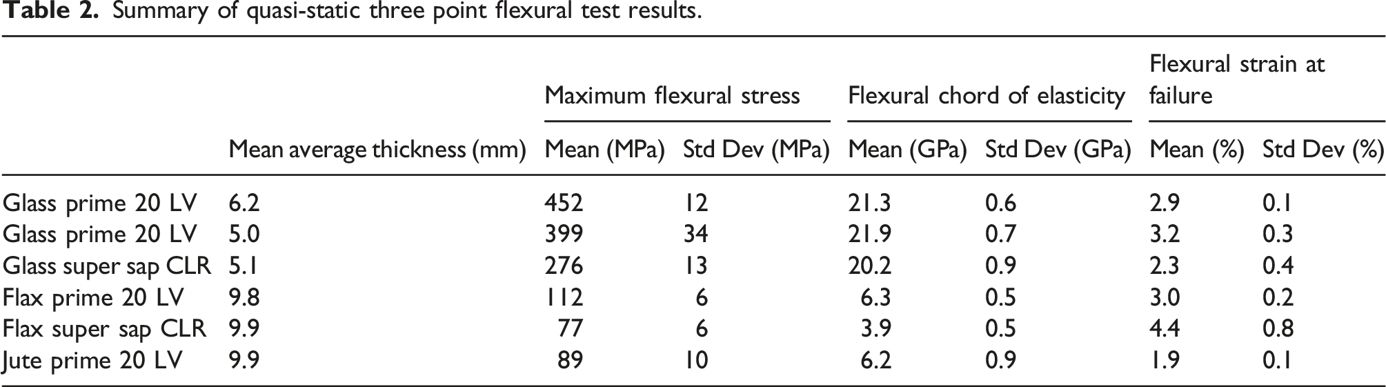
Summary of quasi-static three point flexural test results.
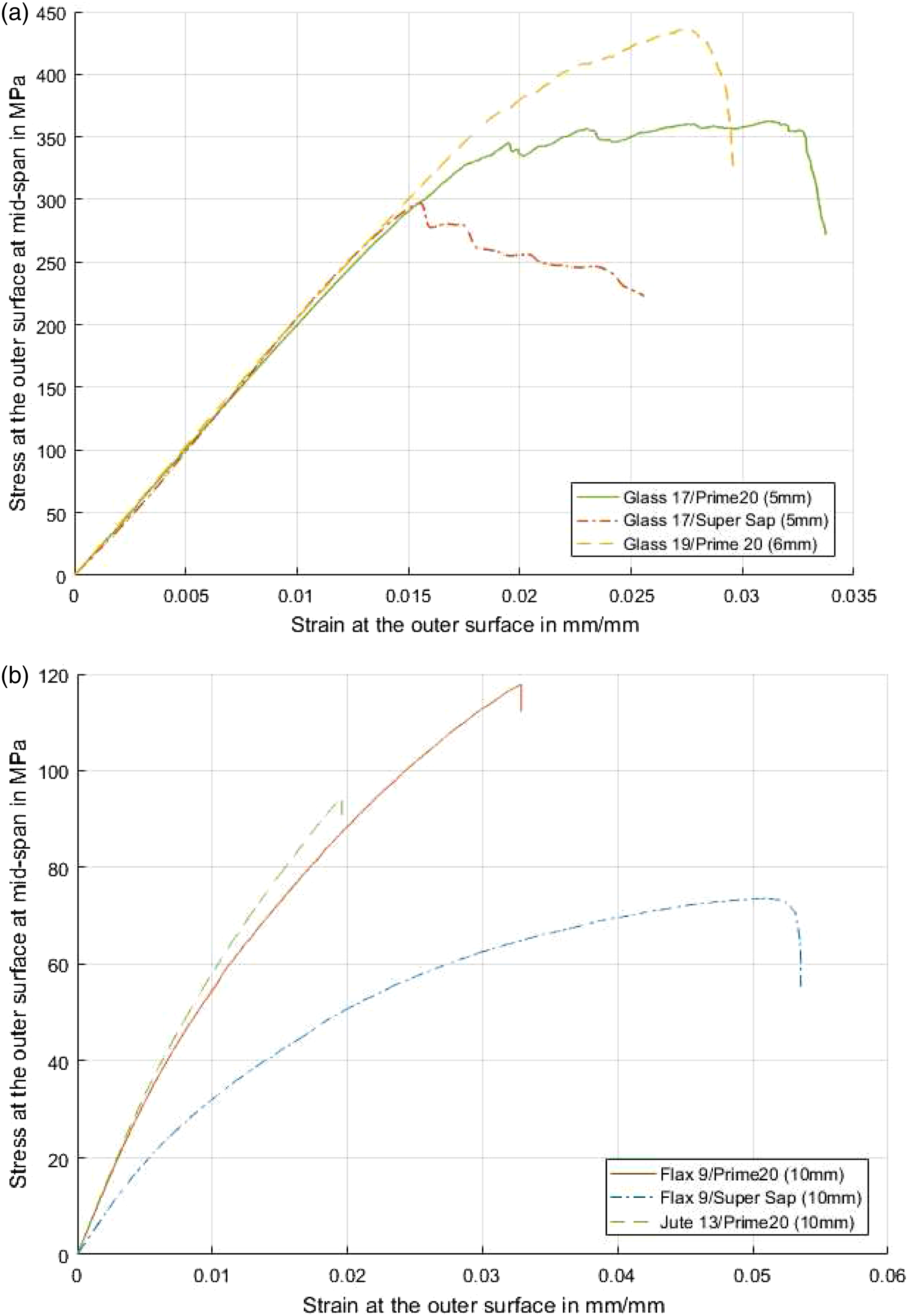
Typical engineering stress-strain curves obtained from quasi-static three point flexure tests (a) GFRP, (b) NFRP.
The specimens containing Super Sap resin exhibited lower peak stresses than their Prime 20 LV counterparts. The GFRP Super Sap specimens exhibited slightly lower failure strains, whereas the flax Super Sap specimens exhibited higher strain to break that the Prime 20 LV ones. In both glass and flax specimens, the change to Super Sap reduced the flexural chord of elasticity, although the difference was greater in the flax (7% reduction in GFRP, 38% reduction in flax FRP), possibly because the flax fibre specimens were already far more flexible. The jute exhibited linear-elastic response and the lowest strain to failure (1.9%), which was consistent with the brittle cracking observed in the specimens. The generally low standard deviations (and coefficients of variation) suggested that the flexural response was repeatable, indicating that the manufacture of the panels was consistent for a given material type. The flexural strength of the jute FRP was within 2.5% of the manufacturer’s quoted value. 43
Mode I interlaminar fracture toughness
The failure of blast-loaded panels are often caused by interlaminar and membrane stresses generated as the panel bends. 50 Although specimen geometry and loading conditions play a significant role in interlaminar stress, the interlaminar strength is a material dependent value. 51 Double cantilever beam (DCB) tests were performed on the GFRP and NFRPs to ascertain their interlaminar Mode I fracture toughness (tensile crack propagation), following the guidelines in ASTM D5528-13. 48 The test specimens were nominally 125 mm long and 25 mm wide. The recommended thickness (3–5 mm) was followed for GFRP, but this thickness would have meant too few plies through the thickness for the NFRPs,51,52 so this was increased to 9 mm to ensure that delamination damage grew sufficiently slowly for stable crack growth.
Tests were performed at 2 mm/min and side-on photographs were taken at intervals of 15 s. Using the photographs and image processing, the crack propagation along the specimen was measured and used in conjunction with the force and displacement data obtained from the universal tension/compression machine. A photograph showing the crack opening of a flax DCB specimen is shown in Figure 2. The image shows the pin attachment between the metal blocks adhered to the DCB specimen and the test machine, the crack insert used for manufacturing and the white painted specimen edge that was filmed during the test. Modified beam theory was used to determine the strain energy release rate (GI), in accordance with Refs. 51 and 52. Photograph of a FRP specimen at the end of a DCB test, where the crack has progressed to the end of the specimen.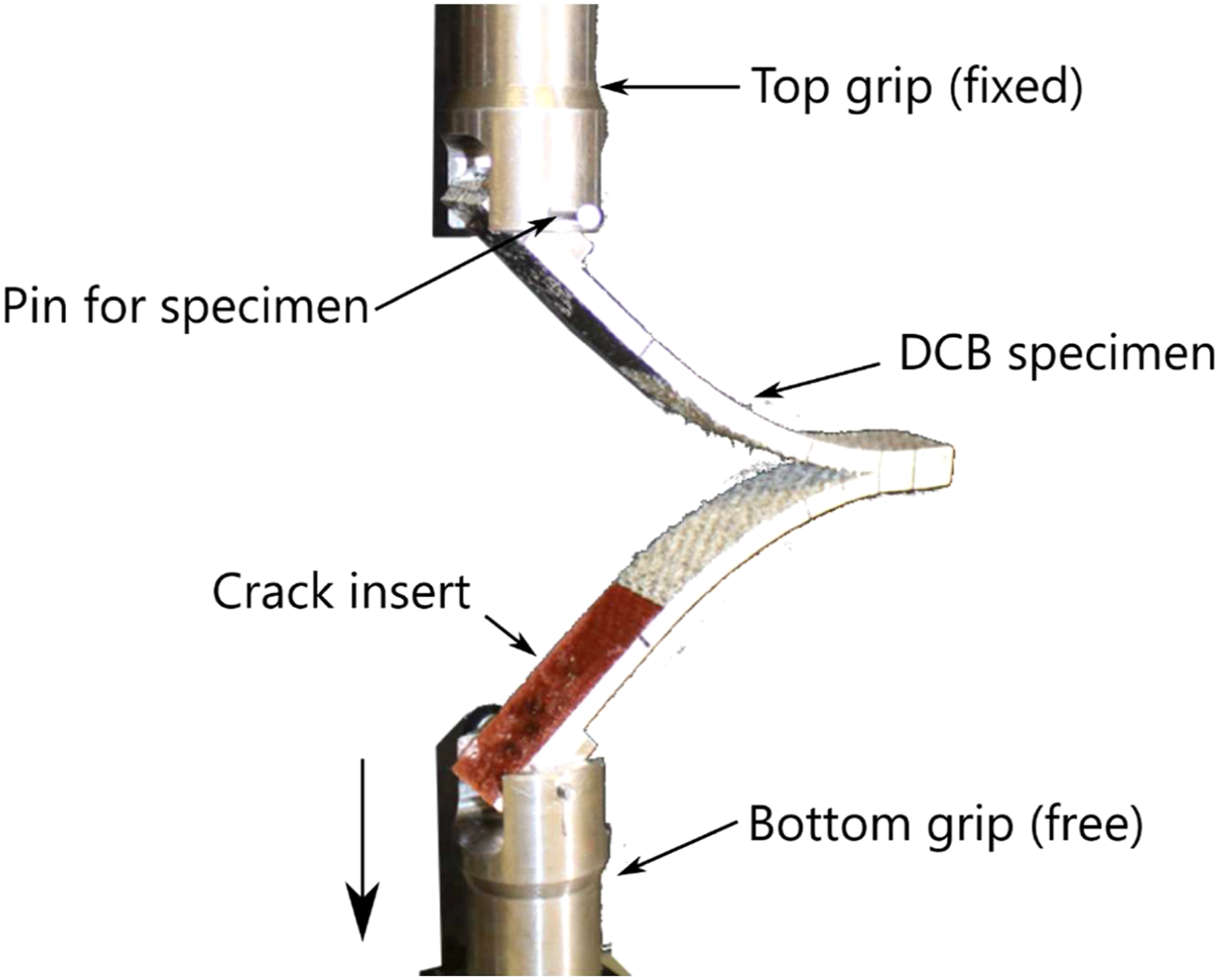
Mean average values for initiation and propagation fracture toughness in GFRP and flax FRP.
Graphs of GI versus crack length are shown in Figure 3 for flax Prime 20 as a typical example. Initially, there was a steep rise in GI before the crack growth initiated. Once the crack began to grow, GI continued to increase more slowly until the cracked reached the far end of the DCB specimen. In flax FRPs, this meant an increase of 45–55% for GIc. Graph of strain energy release rate versus crack length from DCB tests on flax Prime 20 FRPs.
For GFRP, the energy release rate increased only slightly (7–17%) for propagation. It was possible that the interlaminar toughness for the flax FRPs increased because the crack did not stay within the interlaminar zone as a result of the flax fibres and resin having similar properties, meaning that the flax fabric layers did not significantly ‘reinforce’ the resulting composite. This could also explain why the measured interlaminar toughness was higher for the flax fibre. Furthermore, the structure of the individual fibres of the glass and flax fibres differs significantly which would influence the interaction between the matrix and subsequently the interlaminar toughness. The results showed that it is more likely that through-thickness cracks rather than large amounts of delamination would occur in these NFRPs, and that GFRP was more susceptible to Mode I delamination type failures.
Blast test method
Experimental arrangement
The 300 mm x 300 mm GFRP and NFRP panels were subjected to air-blast loading that was generated by detonating disk-shaped charges of PE4 plastic explosive at the open end of a 200 mm long square section blast tube, which directed the blast load towards the panels. The polystyrene pad is used to position the PE4 and has minimal effect on the loading.
53
A schematic diagram of the experiment is shown in Figure 4(a). Using results from previous studies,31,40,41 estimating explosive parameters for the GFRP test was relatively straightforward. For the weaker NFRPs, blast tests on medium density fibreboard
54
were used as a lower-bound reference point. An explosive charge diameter of 30 mm was used throughout the tests. Schematic of the blast experimental arrangement (a) explosive test rig (b) pendulum.
The FRP panels were clamped along all four sides, leaving an exposed area of 200 mm x 200 mm. The front clamp frame was integral with the tube and the rear clamp frame was mounted onto an adapted mount for a pendulum. A square section blast tube was employed to increase the spatial uniformity of the loading and to ensure that the impulse applied directly to the panels and that measured by the pendulum were the same, following previous work by the authors.54–56 The test rig was mounted onto a horizontal pendulum with a single degree of freedom (shown in Figure 4(b)). The impulse was determined from the swing of the pendulum using a laser displacement sensor.
Transient response measurements
High-speed stereo-imaging equipment was mounted to the pendulum to film the panel response, similar to the test arrangement of Curry and Langdon. 56 The rear faces of selected panels were painted with a random black and white speckle pattern. Two high-speed monochrome IDT NRS4 cameras (filming at 30 kfps with an exposure time of 31 µs) and LED lights fitted with a diffuser were positioned to provide a clear field of view. The imaging system was synchronised to the detonation using a break-wire triggering circuit. Digital image correlation (DIC) was used to process the images and obtain the out of plane transient displacement across the mid-line of the panels.
Prior to each experiment, the system was calibrated by moving a checkerboard calibration target to different positions within the field of view and capturing images from both cameras. 56 These images were used to determine the system projection parameter and additional distortion parameters. A 19 × 19 pixels subset size and a grid spacing of two pixels were maintained for all tests, similar to others.56–59 After testing, DIC was used to extract the displacement-time history of the mid-point and the evolution of the deformed mid-line profile at discrete times. Due to limitations on the cameras, this system could only film a central strip across the panel at the requirement frame rate. However, this provided a rich set of displacement-time data, capturing the transient behaviour of the panels. Further details of the transient measurement technique are available in. Ref. 56.
Results and discussion
Summary of NFRP blast test results.
aSignificant fragmentation of panel J13/P20-2 occurred.
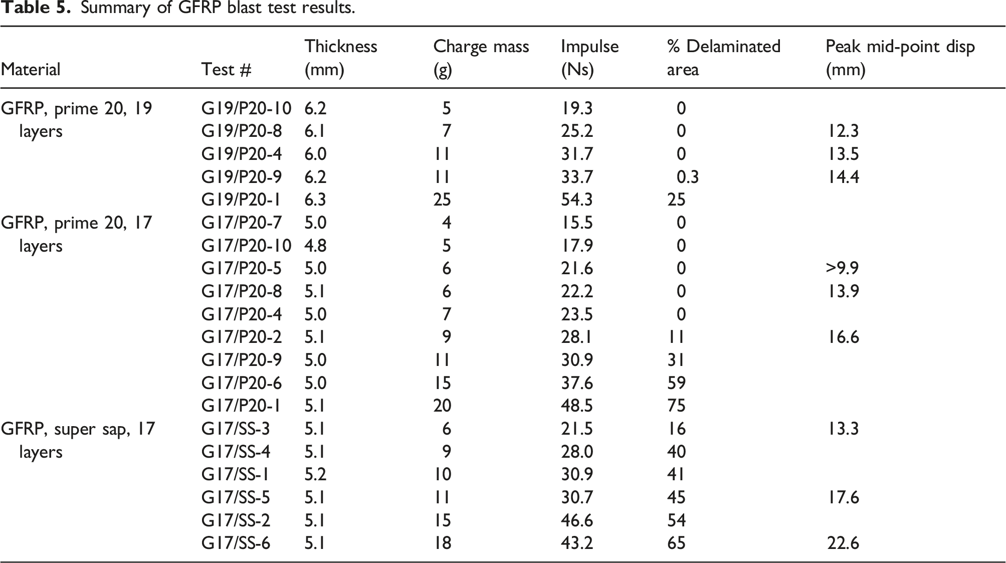
Summary of GFRP blast test results.
After each test, the front and back surfaces of the target plates were visually inspected, measured and photographed. The delaminated area percentage was calculated as the percentage of delamination found in the exposed area of the panel. Delamination was traced from photographs of GFRP panels that were illuminated using a lightbox to highlight the failure mode. The panels were sectioned along the mid-line and microscopy was used to inspect relevant regions at higher magnifications.
The 19 layer (nominally 6 mm thick) glass FRP panels had the same nominal mass as the flax and jute FRP panels; however, they required higher charge masses to promote significant damage and failure within the panels. Additional thinner GFRP panels were made with 17 layers and a nominal thickness of 5 mm to allow a greater range of responses within the 5–20g charge mass range. The effect of using Super Sap resin on blast performances was evaluated using the 17 layer glass FRP panels as a baseline. The 19 layer glass FRP Prime 20 panels were the baseline for comparing the natural FRP panels due to their equivalent mass.
Glass fibre reinforced polymers panels
Photographs of selected blast-tested GFRP panels are shown in Figure 5. The GFRP panels were green and slightly translucent, so damage or discolouration on one surface may be visible (but slightly obscured) on the other side. The front surfaces were discoloured by the blast product residue. The whitening of the panel along the edges of the exposed region indicated delamination. Delamination varied along the edge, being most extensive mid-boundary, matching the expected in-plane strain distribution along the edge and extended into the clamped region. The panel area affected by delamination (not accounting for how many layers were delaminated, which could not be determined by visual inspection) increased with increasing impulse. The linear trend was similar for the Prime 20 and Super Sap GFRPs with the same nominal thickness, whereas increasing the GFRP thickness reduced the extent of the delaminated area (a linear trend with a lower gradient). Photographs of (a) damage at the clamped boundary in panel G17/P20-4 (Prime 20, 7g), (b) damage at the clamped boundary in panel G17/SS-6 (Super Sap, 18g), (c) front surface of G17/SS-6 (Super Sap, 18g) (d) Back surface of G17/SS-6 (Super Sap, 18g).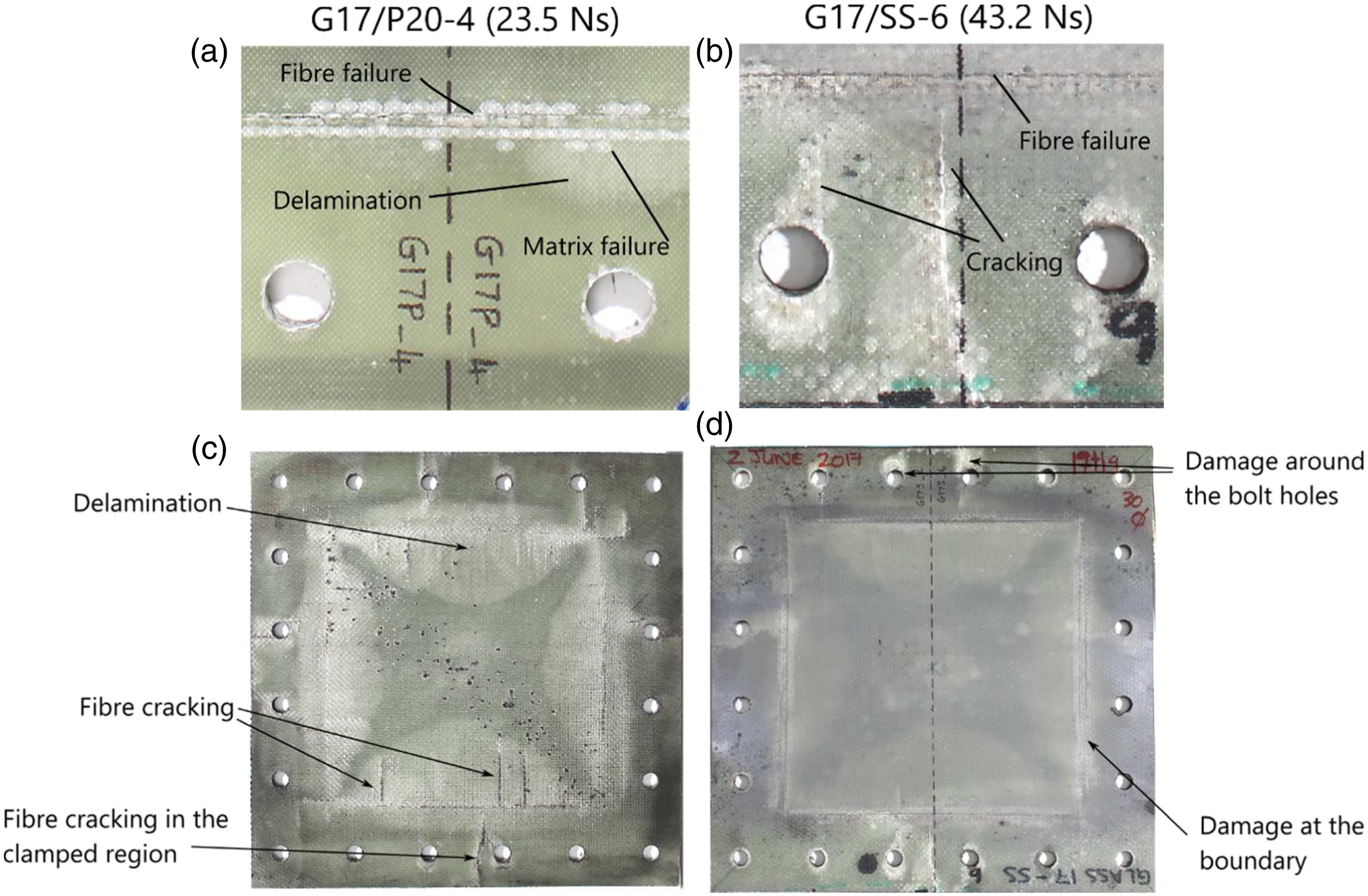
Matrix damage, delamination and some fibre breakage were evident at the edge of the clamped boundary (Figures 5(a) and (b)). Boundary conditions were particularly critical in reinforced polymer composite panels, as the clamped edge acted as a bending and shear failure initiation point. Cracking and matrix damage were more severe in the Super Sap panels, as shown in Figure 5(b). Extensive cracking around the bolt-holes was present in the Super Sap panels and not in the Prime 20 ones.
Increasing the charge mass in the 17 layer GFRP panels resulted in delamination in the centre of the panel as well as the boundary regions, with similar patterns were observed for both epoxy types. However, additional cracking and matrix damage were evident in the Super Sap panel exposed areas (Figures 5(c) and (d)). There was no discernible permanent through-thickness displacement due to the elastic nature of the composite.
Photographs of samples taken from the boundary and delaminated regions of selected glass FRP panels and viewed under the microscope are shown in Figure 6. Figure 6(a) shows the panel boundary. An out-of-plane angled crack and fibre pull-out are both visible. The cross-section view, in Figure 6(b), shows delamination failure, where two layers of woven fabric that have been separated by in-plane cracking. A top view of a delaminated surface is shown in Figure 6(c); the fibres are intact but the resin has failed. Stereomicroscopy images from the glass FRP panels (a) fibre pull-out and cracking (b) delamination, side view (c) top view of the delaminated surface.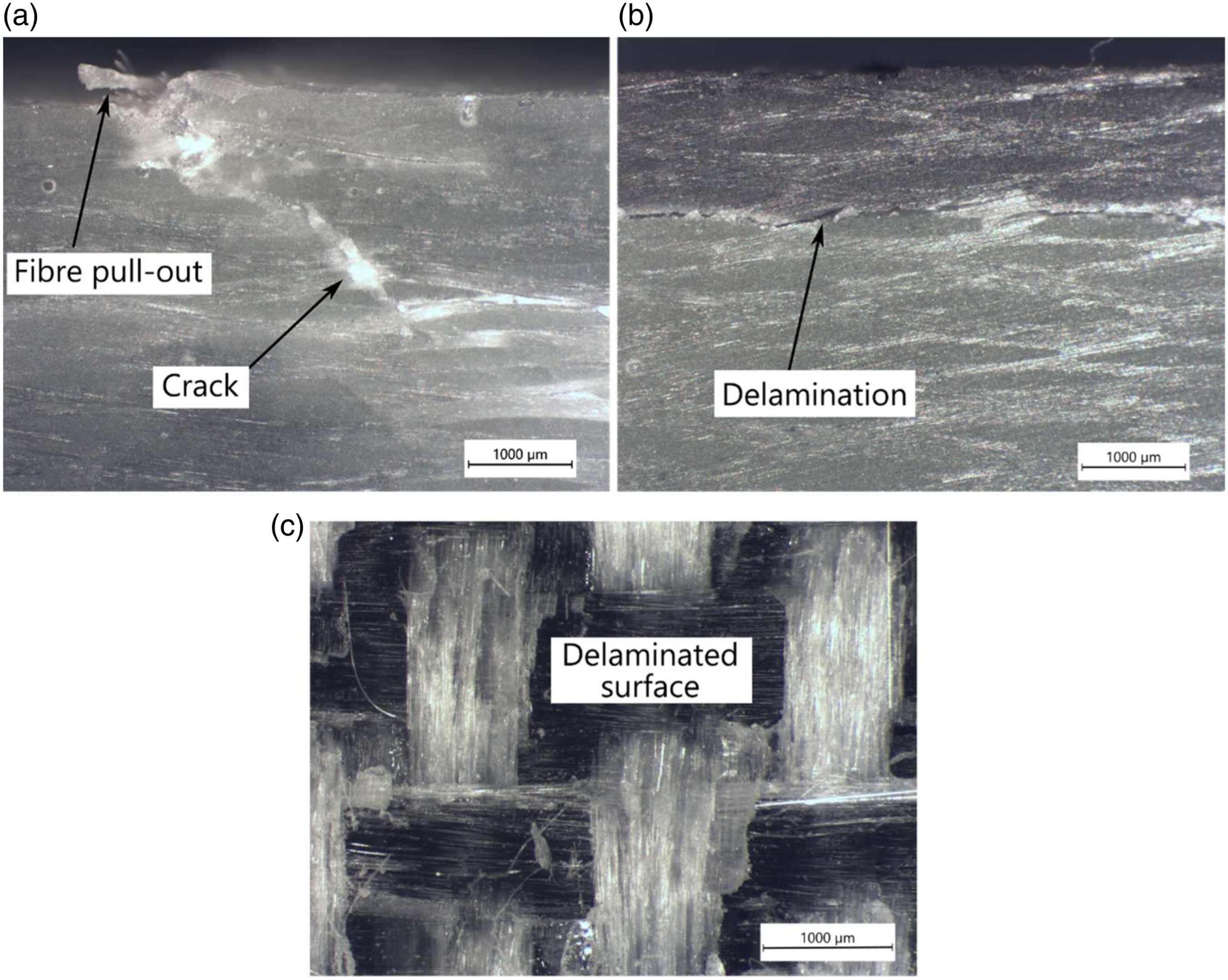
Flax fibre reinforced polymers panels
Photographs of selected blast-tested flax FRP panel surfaces are shown in Figure 7. As the panels were not translucent, the presence of delamination was assessed by sectioning the panels. Any likely delamination would have been found immediately adjacent to the cracked regions, or around the holes for mounting, but visual inspection through the thickness revealed no such damage. The microscopy images also failed to reveal any delamination. Hence, delamination was considered unlikely elsewhere in the panel and was neglected as a significant failure mode. Delamination was not a major identified failure mechanism in the flax panels, instead, matrix damage and cracking failures dominated the response. The cracks on the front and rear surfaces are indicated by the red (centre) and green (boundary) lines in Figure 7. Rear surface cracking was more extensive than the front surface cracking. This was consistent with the flexural test results, where the flax FRP failed due to cracking of the rear (tensile) surface. At 11 g, perforation of the panel in the centre was evident for both resin types. Photographs of the front (top) and rear (bottom) surfaces of selected flax FRP panels (a) F9/P20-1 (6g) (b) F9/P20-5 (9g) (c) F9/P20-2 (11g).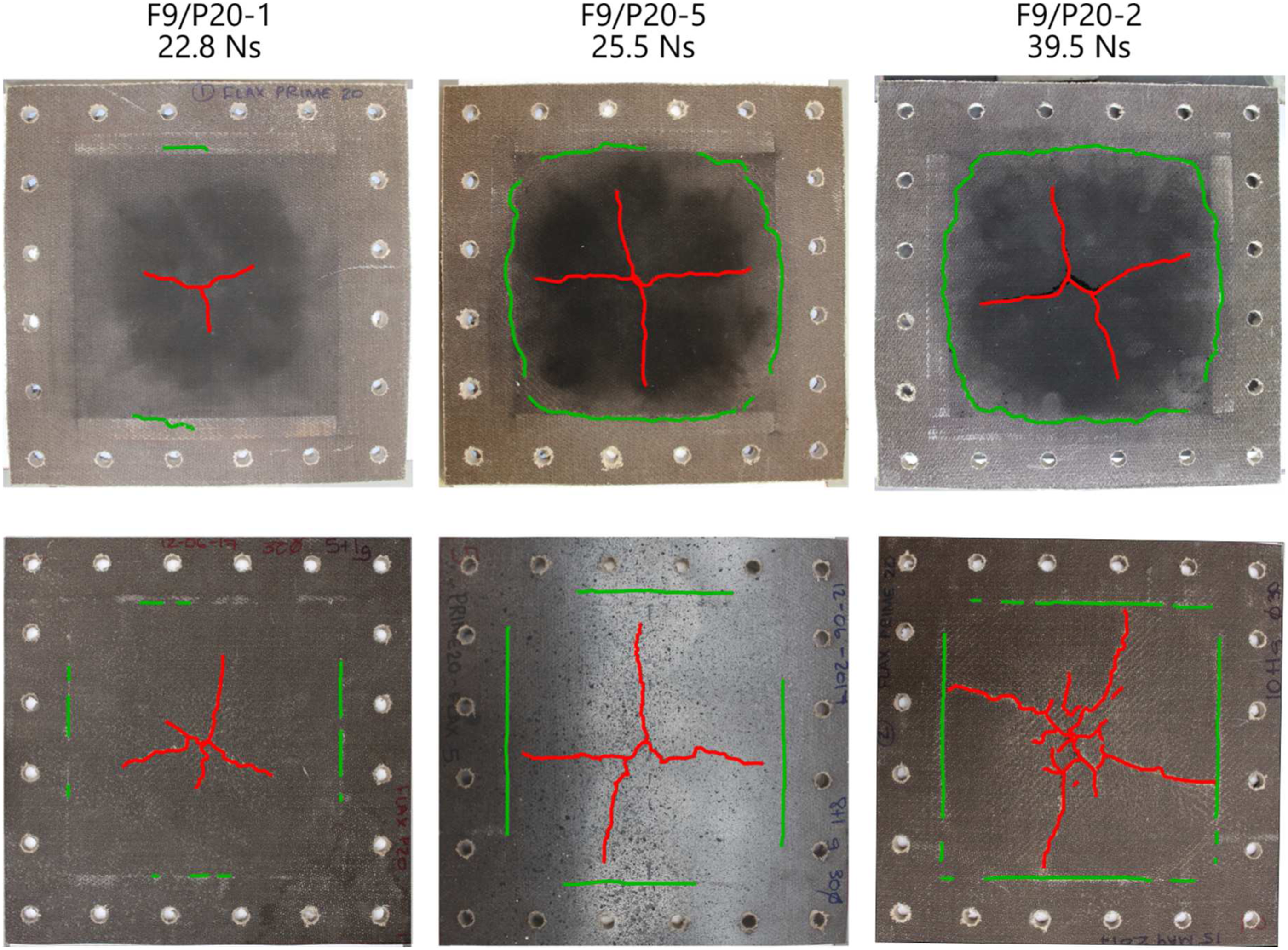
Microscopy showed that, prior to testing, there was no discernible difference in the flax FRPs manufactured with either resin system, with both panels containing very small voids (less than 100 μm) randomly distributed through the resin. In-plane fibre pull-out, out-of-plane fibre fracture and cracking were observed using stereomicroscopy, with the resin type having little influence on the failure mode.
The delamination failures observed in glass FRPs were not noticeably present in the flax FRPs, probably due to the higher GIc of the flax FRPs compared to the glass FRPs. In general, flax FRPs using Super Sap exhibited the same failure types as the Prime 20 panels, but with slightly less damage for a given charge mass. This was consistent with the material characterisation experimental results, where the Super Sap flax FRPs exhibited greater ductility in flexure and higher GIc values for crack initiation and propagation.
Jute fibre reinforced polymers panels
Photographs of selected blast-tested jute FRP panel surfaces are shown in Figure 8. Damage modes were similar to the flax panels, with cracking failures dominating the response. The Jute FRPs were less consistent; their low fibre strength meant that the panel properties were more influenced by the resin. Jute FRPs exhibited the most brittle-type behaviour of the tested materials, with perforation achieved for a small increase in impulse and at lower charge masses than for flax or glass FRPs. At 11 g, complete fragmentation of the panel occurred, as shown in Figure 8(c). Photographs of the (top row) and back (bottom row) surfaces of selected jute FRP panels (a) front face, J13/P20-3 (7g) (b) rear face, J13/P20-3 (7g), (c) rear face, J13/P20-2 (11g) with fragments replaced.
Sectioning the panels (typical examples shown in Figures 9(a) and (b)) revealed that they failed due to through-thickness cracking. Figure 9(c) shows a stereomicroscope image of a typical fibre fracture in a jute FRP, and Figure 9(d) shows the edge of a through-thickness crack edge. The jute fibres appeared to be well encapsulated and there is no sign of fibre pull-out, both indicated good bond between the resin and fibre (this supports the manufacturer’s claim
43
that sizing of the jute fabric was unnecessary). Through-thickness cracking was the major failure mode in the jute FRPs, which was consistent with the DCB test results that showed the in-plane crack propagated through the specimen thickness, invalidating the GI measurement. Photographs showing failures in selected jute FRP panels (a) mid-line cross-section of J13/P20-1 (6g) (b) mid-line cross-section of J13/P20-1 (7g) (c) stereomicroscope image showing typical fibre fracture in Jute FRPs (d) stereomicroscope image of crack edge in jute FRP.
Transient response
GFRP response
The GFRP panels exhibited sinusoidal-shaped transient mid-line deformed profiles, similar to the example presented in Figure 10. Some typical mid-point displacement-time histories are shown in Figure 11 for different charge masses/impulses and different resins. Elastic vibrations dominated the transient responses. Permanent displacements of less than 1 mm were measured after testing, less than 20% of the original panel thickness. There was an initial steep rise in displacement to its peak, followed by viscously damped oscillations where the peak magnitude of each successive vibration decayed. In Figure 11(a), the first part of one of the traces (G17-P20-5) is missing due to difficulties in identifying the speckle pattern markers during DIC. However, when the trace reappears after 1.5 ms, it is very similar in magnitude and shape to the other test at a near-identical impulse (G17/P20-8). This indicates satisfactory repeatability in measuring the transient response. Transient deformed profiles for GFRP panel G19/P20-4 (19 layers, Prime 20, 11g). The triangles indicate the direction of motion. Graph showing transient mid-point displacement-time histories for GFRP panels (a) 17 layers, Prime 20 (b) 17 layers, Super Sap.
Changes in the natural period of vibration were elucidated by monitoring the time between peak-to-peak oscillations. No significant variation was observed in the 19 layer GFRP panels for charge mass detonations up to 11 g, which is consistent with the onset of delamination observed at this charge mass. For the 17 layer Prime 20 glass FRPs, there was an increase in the peak-to-peak time period for test G17/P20-2 (9g, 28.1 Ns), indicating a small decrease in the angular frequency of vibration. As panel mass was conserved, this change was attributed to a 7.5% decrease in panel stiffness compared to the other tests (without any difference in the panel thickness). Decreasing panel stiffness must be the result of internal damage to the panel; this corresponded with the visual observations of delamination initiation in these panels at 9 g (11% of exposed area).
The Super Sap GFRPs transient mid-point displacement-time histories (Figure 11(b)), were initially similar to the Prime 20 panels, but as charge mass increased to 11g, the Super Sap panels delaminated more (45% exposed area in G17/SS-5, compared to 11% in G17/P20-2). This was evident in the post-peak vibration behaviour of the Super Sap panels. The post-peak angular frequency substantially decreased, corresponding to a stiffness loss (relative to the 7g panel) of nearly 22% due to internal damage. At 18 g PE4, the Super Sap panel exhibited further degradation in stiffness (nearly 47% compared to the 7 g panel) and had a delaminated area of 65%.
Flax FRP Response
Panels containing flax tended to fail by cracking, as shown in Figure 7. Crack formation in the panel centre produced discontinuities in the speckle patterns on the rear faces, causing large gaps in the transient deformed profiles obtained from DIC one cracking occurred. Similar to GFRP, there were also some difficulties in capturing the early time response in some tests due to local pattern recognition difficulties. Despite these difficulties, however, some transient measurements were still possible.
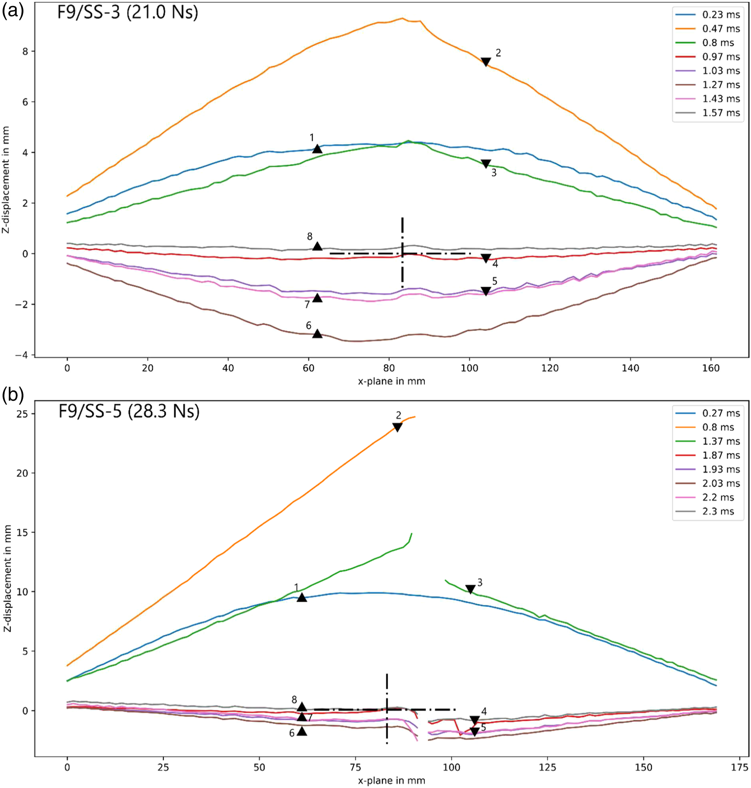
The 5g charge tests in FFRP panels containing different resins exhibited similar viscously damped harmonic oscillatory behaviour, with near identical peak displacements and damped periods of oscillation (shown in Figure 12). The reduction in amplitude of successive peaks was significant, consistent with the damping noted in Refs. 3 and 7. The transient mid-line deformed profiles (Figure 13(a)) were also similar. At 7 g, there were gaps in the displacement-time histories due to the crack formation (Figure 12) that made it difficult to compare the peak transient displacements. There was, however, a greater decrease in the post-peak oscillation frequency in the Prime 20 panels. This decrease suggested a loss in panel stiffness of 47% for the Prime 20 panel and 36% for its Super Sap counterpart (without any difference in the panel thickness). Thus, the transient post-peak oscillation response suggested that the Prime 20 panel exhibited internal damage that resulted in a greater degradation of its stiffness. Graph showing transient mid-point displacement-time histories for blast-tested FFRP panels containing (a) Prime 20 (b) Super Sap. Transient deformed profiles for Super Sap FFRP panels obtained from DIC analysis, where the triangles indicate the direction of motion (a) F9/SS-3 (5g) (b) F9/SS-5 (9g).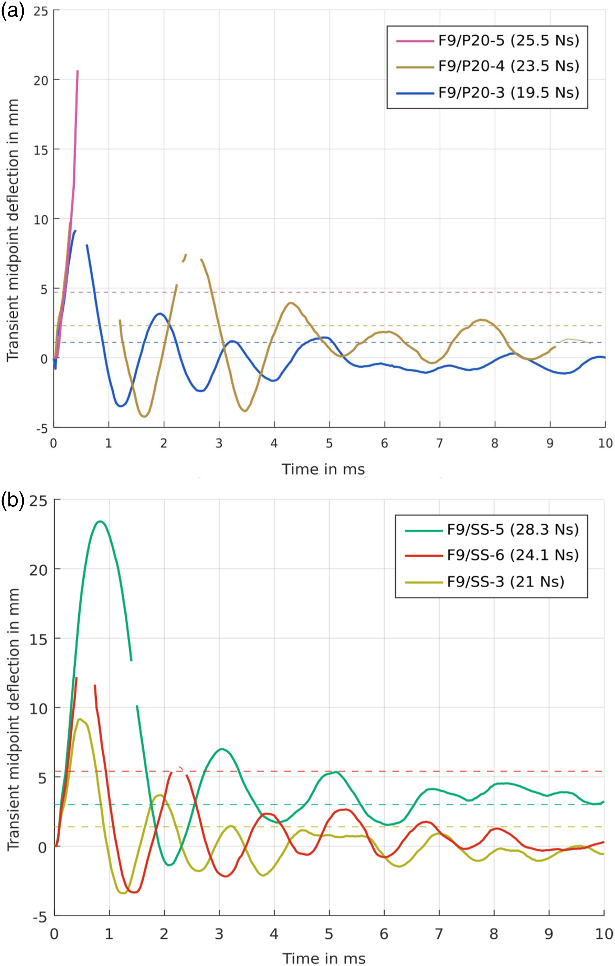
For a 9g detonation, the Prime 20 flex FRP panel displacement appeared to exceed 30 mm (Figures 12(a) and (b)). However, the transient mid-point displacement history should be treated cautiously as the panel exhibited extensive cracking. Stills from the camera footage are shown in Figure 14, where the field of view is a mid-line strip across the rear face. The cross indicates the panel centre and the speckle pattern is visible. Figure 14 shows a central crack formed before 130 µs, and that the motion in the central area was at high velocity (motion blur is present in the image). The black area covering part of the speckle pattern in Figure 14 is the gaseous combustion products being released through the cracked region, preventing the transient mid-point displacement history being recovered during DIC analysis. The peak displacement of the Super Sap panel, estimated at 23.4 mm (Figure 12(b)), should also be treated cautiously due to extensive cracking in the panels that appeared to just miss the panel mid-point. Stills from high-speed camera footage showing crack formation and escaping gas products from a blast-loaded FFRP panel (F9/P20-5, 9g PE4).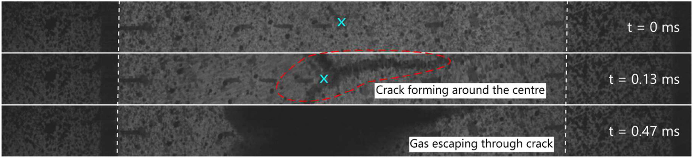
Jute FRP Response
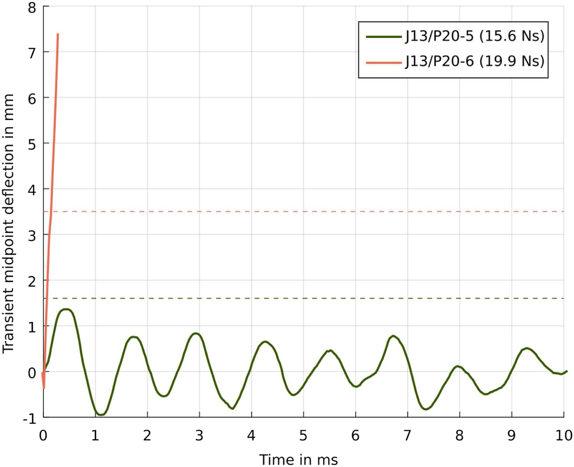
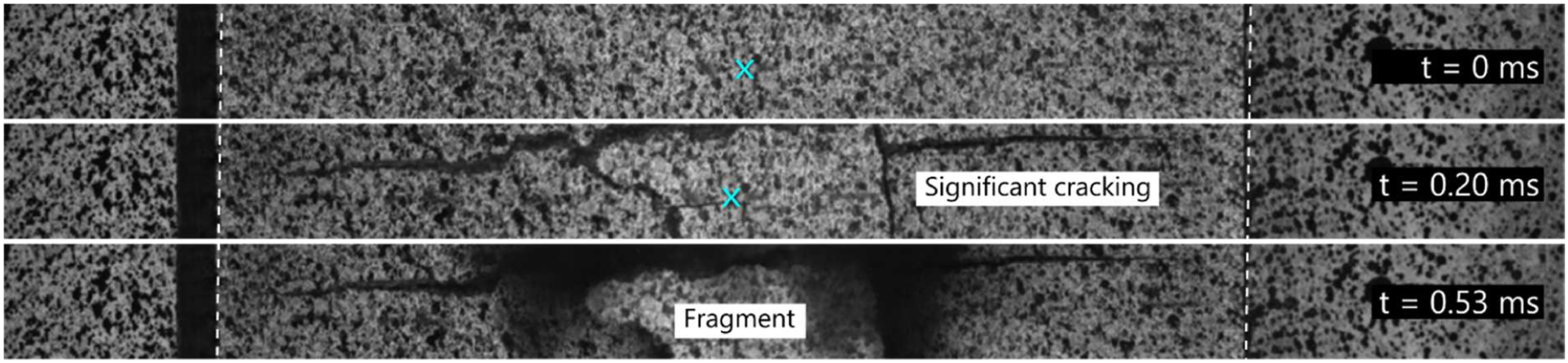
The 4g detonation produced very small deformations, shown in Figures 15(a) and 16, with a dome-shaped mid-line profile exhibiting a slightly jagged due to the resolution of the displacement measurement when displacements are small (less than 2 mm). The displacement-time history showed an initial peak displacement of 1.3 mm followed by viscously damped harmonic vibration response. The transient mid-line profiles for a 5g test are shown in Figure 15(b). During the first 300 µs (points 1* and 2*), the profile resembled a dome shape. After this, DIC could not determine the out-of-plane displacement at certain points along the mid-line, due to extensive crack formation. The camera footage (see Figure 17) indicated significant cracking in the first 200 µs and extensive fragmentation within the first 500 µs, confirming the reason for decorrelation. The profile shape in Figure 15(b) seemed to become more conical and asymmetric. The mid-point displacement-time history for a 4g detonation is also shown in Figure 16, but all data after 300 µs is missing due to this decorrelation caused by cracking. Transient deformed profiles for jute FRP panels obtained from DIC analysis, where the triangles indicate the direction of motion (a) J13/P20-5 (4g), (b) J13/P20-6 (5g). Graph showing transient mid-point displacement-time histories for blast-tested jute FRP panels. Stills from high-speed camera footage showing crack formation and escaping gas products from a blast-loaded jute FRP panel (J13/P20-6).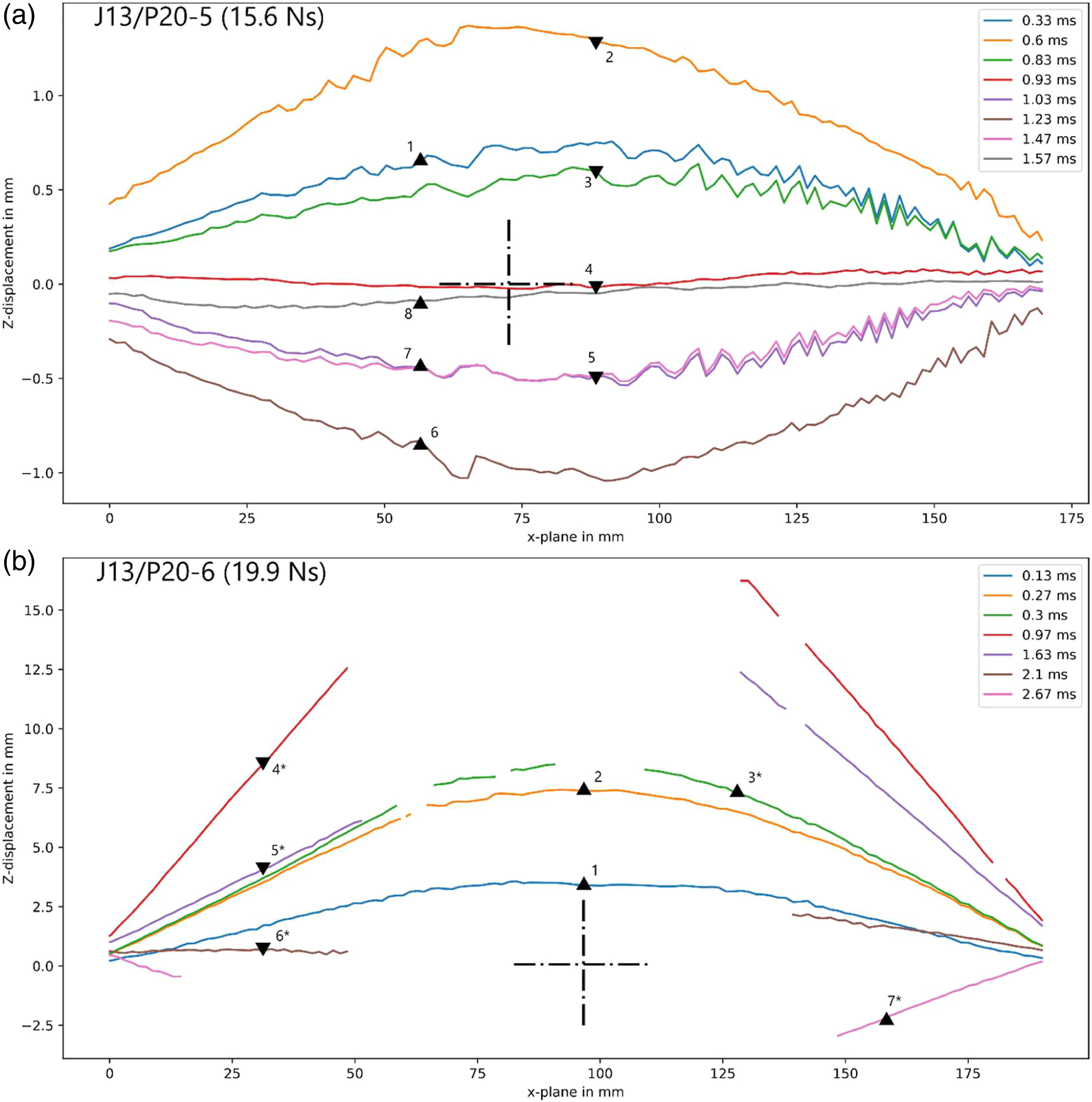
Challenges of using DIC for transient response measurements
There are some major technical challenges in using DIC and high-speed imaging for transient response measurements when blast loading FRP panels are in such close proximity. Available lighting in the enclosed space limited the choice of exposure time and frame rate. Relatively long exposure times (31 µs) were required to enable sufficient lighting, but this produced motion blur in early images when the plate velocity was very high. The frame rate (30 kfps) was also limited by the lighting and meant that there were a relatively small number of frames up to the peak displacement of the panels.
The cracking failure mechanisms in the NFRPs occurred during the first 1 ms of response, while the rear surface was under tension. Cracking caused discontinuities in the speckle pattern of the rear face, making it difficult (and sometimes impossible) to determine the out-of-plane displacements using DIC. This led to ‘drop outs’ in the data for specific time periods, depending on the location of the cracking. If the cracking occurred off-centre, it was often possible to recover large portions of the mid-point displacement-time history. Furthermore, once perforation occurred, ingress of detonation/combustion products and dust into the camera field of view obscured the speckle pattern, causing a total loss of data across that region.
The challenge for measuring transient response in the GFRP panels was managing the light flash from the explosive detonation. The GFRP panels were translucent, meaning that the light flash can penetrate through the panel thickness and is detected in the camera images, leading to decorrelation issues. These were overcome by applying several layers of opaque black paint to the rear side of the GFRP panels prior to painting the speckle pattern to block the explosive light flash.
The post-peak displacement oscillations indicated viscous damping (decreasing peak magnitudes with successive oscillations) and the increase in peak-to-peak period was related back to internal damage of the panel causing a loss of stiffness. This type of transient behaviour and stiffness degradation has not, to the authors’ knowledge, been previously measured during close proximity blast testing.
Non-dimensional analysis
Nurick and Martin
60
proposed a non-dimensional impulse expression for blast-loaded quadrangular plates that exhibited significant plasticity. This expression, shown in equation (1), enabled comparison of panels of different geometry (exposed area and thicknesses) and materials (densities and characteristic stresses). Modifications to account for load localisation and stand-off distance have been proposed.53,61 Linear correlation between the permanent displacement (normalised against plate thickness) and this non-dimensional impulse was observed. This approach has been considered robust for over 30 years for metallic materials.
60
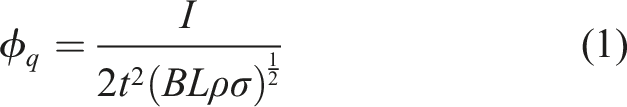
Langdon et al. 62 applied the non-dimensional analysis to blast-loaded fibre reinforced polymers, but because of their lack of plasticity and elasticity-dominated responses, the approach was not a useful one. In this work, instead of normalising the permanent displacement, the peak transient displacement was used. Furthermore, as the cracking observed in the blast tests seemed to be similar to the bending response, the peak flexural stress from the three point bending tests is used as the characteristic strength. While four point bending would provide a more uniform bending moment distribution across the specimen, the three point bend test has been used before. 62 As long as the test conditions are the same (that is, three or four point bending), the characteristic stress should vary by the same percentage, allowing this to be a characteristic strength that is useful for comparing materials.
Although the findings cannot be compared directly with results for steel, it is interesting to note that a linear relationship is still apparent (Figure 18) when the Jute, Flax and Glass FRPs are plotted in this modified non-dimensional form. The R2 correlation coefficient (0.86) obtained from a linear regression fit to the data is lower than that obtained for metals but still indicated strong correlation. Graph of non-dimensional transient displacement versus non-dimensional impulse (a) grouped by panel type (b) showing linear best-fit trend-line.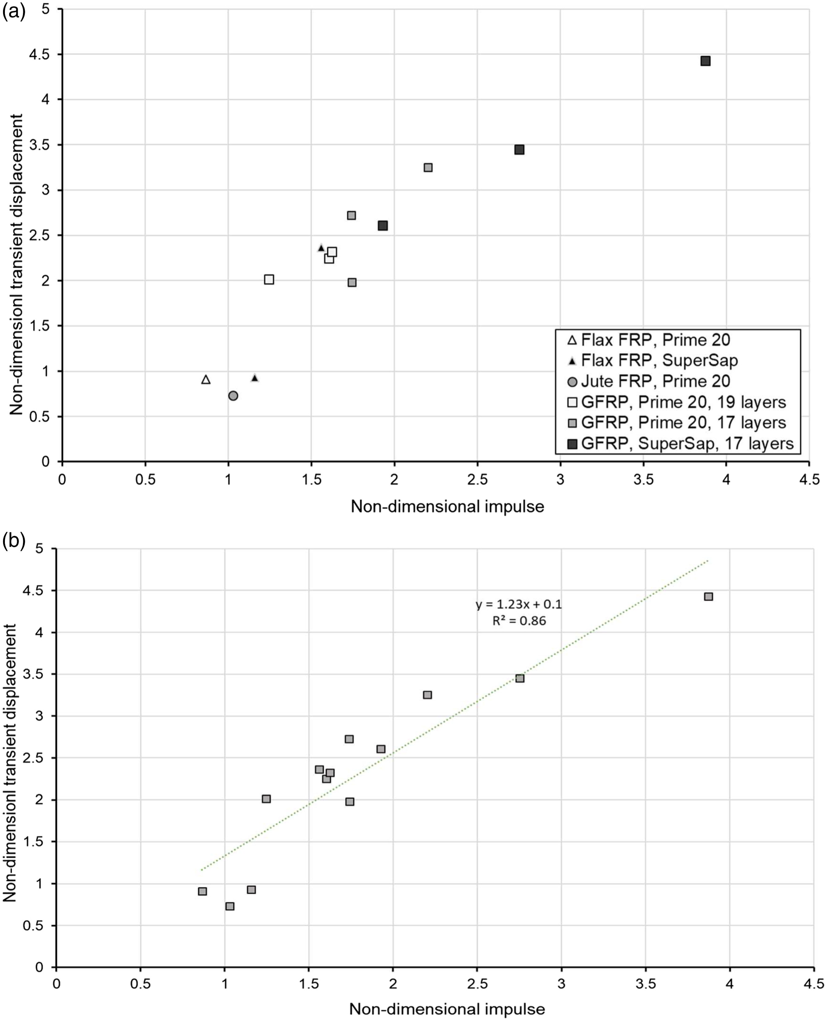
Based on the outcome of this modified non-dimensional analysis, one can predict the peak elastic response of quadrangular composite panels. It should be noted, however, that this approach was based on a limited set of data and should be extended to include data from other tests in the future.
Failure initiation and progression
Failure initiation charts have been used to summarise the failure progression within blast-loaded FRP laminates and sandwich panels, and as a means to elucidate the influence of material type and geometric parameters.
40
In this work, a failure initiation chart was constructed to indicate the onset of a failure mode for range of charge masses for each material, shown in Figure 19. Similar to charts by Langdon et al.,
40
dotted lines were used to show the combination of failure modes at higher charge masses. Failure mode initiation chart.
Figure 19 illustrates that blast protection specialists can neglect delamination when modelling and designing flax or jute FRPs, but that delamination must be considered for GFRPs. It also illustrates the considerable advantage of increasing thickness in FRPs. Boundary damage at relatively low charge mass detonations was a significant issue, suggesting that careful design of mounting and attachments for FRP panels will be essential to ensuring premature failures do not occur in practical situations.
Cracking failures in the GFRP panels only occurred at very high charge masses, relatively to other failure modes, whereas cracking was a major failure type in NFRPs. In-plane fibre pull-out and through-thickness crack propagation were both observed, with through-thickness cracking causing extensive fragmentation in Jute FRPs at very low charge mass. The cracking failure mechanism must be carefully considered when simulating the behaviour of natural FRPs under blast conditions and is worth further study. Although many of these observations are also true under most quasi-static conditions, this work confirms their importance when blast shock loads are considered.
Conclusions
The response and failure of blast-loaded FRP panels containing sustainable constituent materials have been experimentally investigated by detonating small charges of plastic explosive at a known distance from the panels. The results showed that the fibre type was of primary importance, and that NFRP panels were far less blast resistant than their equivalent mass GFRP counterparts. The jute FRPs were the least blast resistant and exhibited through-thickness cracking leading to complete fragmentation. The flax FRP panel outperformed the jute and exhibited fibre pull-out failures in additional to cracking.
The influence of the resin depended on the fibre system. For GFRPs, using the Super Sap resin caused a small degradation in the blast performance of the panels, but not significantly so. In the flax FRPs, the Super Sap panels performed better than their Prime 20 counterparts as the fibre and resin strengths were more comparable than in the glass FRP panels. The transient results showed that all the FRPs exhibited high-peak displacements and viscously damped elastic vibrations. The initiation of internal damage (such as cracking or delamination) measurably reduced the panel stiffness, determined by comparing their post-peak oscillation periods. A linear relationship between normalised peak displacement and non-dimensional impulse was observed when transient deflections and peak flexural stress were substituted into Nurick and Martin’s approach, 60 a new adaption for FRPs of an analysis that has worked well for metallic panels.
The results indicated the strong influence of fibre type on important failure mechanisms and their development within blast-loaded FRPs. Encouragingly, they also showed the potential of more sustainable plant-based resin systems. The observations were consistent with quasi-static flexural and Mode I interlaminar toughness test results, despite the intense, high-rate loading generated by the close proximity explosive detonations. This paper provides valuable data for validation of modelling for FRPs of different materials. It offers useful insights regarding the potential of sustainable alternatives for FRP construction and highlights the ability of quasi-static test methods to provide data that may help in ranking blast protection potential of different FRP candidates.
Footnotes
Acknowledgements
The authors are grateful to the National Research Foundation (NRF) of South Africa for their financial support. Opinions expressed and conclusions arrived at, are those of the authors and are not necessarily to be attributed to the NRF. The authors would also like to thank the staff of the Mechanical Engineering workshop at UCT for their assistance in machining the specimens and pendulum parts.
Declaration of conflicting interests
The author(s) declared no potential conflicts of interest with respect to the research, authorship, and/or publication of this article.
Funding
The author(s) received no financial support for the research, authorship, and/or publication of this article.