
Abstract
Fiber-reinforced polymer (FRP) composites are particularly suitable for spring applications due to numerous advantages like lightweight design, intrinsic damping, or chemical resistance. Although there are many studies on the properties of FRPs and even some on springs made out of these materials, there is no holistic method for FRP spring design. Therefore, this article focuses on a new approach that combines all relevant design steps. This includes a spring-related overview of requirements and associated FRP properties, as well as recommendations regarding material and spring type selection with a specialization on polymer composite volute springs. Thereupon, a mountain bike rear suspension spring was designed and produced. These carbon fiber-reinforced polymer (CFRP) lightweight spring, which weighs only half of the metal spring, was examined in static and cyclic experiments. Important results of the tests are a lower spring rate than theoretically expected as well as a loss of stiffness of the spring of about 25% after 25,000 full deflections just before failure. Downhill riding tests were carried out and showed comparable driving characteristics as when using conventional steel springs. The research is a contribution to FRP spring design considerations as well as to extend the range of applications for composite springs, and especially volute springs, in the future.
Keywords
Introduction and motivation
Introduction and research background
Technical springs are indispensable in everyday life. They store energy and provide forces, serve to secure a position, or work as an element for damping, measuring, bearing, or resting, to secure force pairings or to eliminate clearance. 1 A wide variety of designs have been developed over the centuries. The areas of application are as varied as their shape: their use extends from vehicle construction, to the engineering industry, to mechanisms, for example, for furniture, locks, closures, or garage doors. The springs used in technical applications today consist almost exclusively of high-strength spring steel.
Mobility and lightweight construction are currently considered mega trends of which numerous requirements and properties that are important for these trends could be realized by using springs made of fiber-reinforced polymer composites (FRPs) instead of their steel counterparts. In general, the advantages as well as the difficulties of deploying fiber-reinforced polymers are well known. The challenging material characteristics are continuously studied, for example, for automotive applications, 2 fatigue life modelling for construction, 3 or even long-term exposure in freezing–thawing environments. 4 The weight-related mechanical properties of laminates can exceed those of metals in the fiber direction and underline the potential for lightweight (spring) design, as pointed out in Reference 5.
In addition to the mechanical and optical properties, chemical and corrosion resistance are situationally advantageous as well. Highly stressed areas can be locally strengthened or weakened by adjusting the layer thickness, fiber orientation, or material. The inhomogeneity and anisotropy associated with the polymer composites requires special knowledge and practical experiences. In the past, however, the costs for materials and production technologies exceeded those for (spring) steel and spring production. The fact that polymer composites have long been established for functional parts and machine elements is often only known to experts. However, the focus of this work should not be on the material properties themselves but development and test of a new holistic method for FRP spring design.
Fiber-reinforced polymer springs have been in use since the 1980s, with the first prominent FRP series spring appearing in the Chevrolet Corvette C3 (produced from 1967 to 1982). Since 1981, a transverse leaf spring made of glass fiber-reinforced polymers (GFRPs) was installed on the rear axle, which weighed only about 4 kg and had fivefold higher life expectancy than its steel counterpart. 6 Daimler conducted a field test implementation using the T1 truck in 1982 and due to successful demonstration, GFRP leaf springs were designed for vehicle weights of up to 10t and installed in the Sprinter (T1 successor) as a GFRP transverse leaf spring. In an MAN truck weighing up to 24t, weight savings of 65 kg could be achieved compared to the steel spring with fourfold increase across rough road distances. 7 As a result, several other vehicle manufacturers began installing GFRP leaf springs.8–10 The development and manufacture of FRP leaf springs has evolved to such an extent that they are no longer only suitable for small series in trucks or cars. Several manufacturers aim for large-scale production; for example, SGL Carbon produced over one million GFRP leaf springs for Volvo XC90. 11
Further studies were made for bending loaded tape springs, 12 bow springs/C-springs,13–15 or ring springs. 16 Based on this, the so-called snail leaf spring was invented. 17 As a C-shape with a non-constant strip thickness, the spring has different spring rates depending on the installation position. A simple production and the adjustable stiffness open up numerous potential areas of application. However, commercial applications are not known.
Furthermore, a tension leaf spring was presented by Mubea.18,19 In addition to the main function as a leaf spring, the curved end allows a length compensation between the spring mounts. The usual shackle can be omitted. The advantages of free design enabled an optimal spring design. The weight reduction is up to 75% (50 kg/axle).20,21 Other bending-loaded FRP springs are meander springs21,22 or meander spring arrangements like Danto-springs, 23 spiral springs,16,24 and wave spring stacks. 25 Investigations on these are currently limited to prototypes, and comparable spring properties were not published.
Torsion-loaded FRP springs have also been tested for several decades. The first known cylindrical laboratory test specimens were manufactured and tested in 1983 with a diameter of 10 mm. Based on this, drive shafts with a diameter of 60 mm were manufactured, which could transmit 280 kNm at 60° rotation until they broke.26,27 Other torsion springs were examined for the use as vehicle stabilizers by authors in References 18 and 28–30. Although the references were able to show both technical and economic advantages, no applications of larger quantities are known.
Helical compression springs are among the most widely used in the field of metal springs and are therefore particularly interesting for lightweight alternatives. For example, in References 27 and 31 compression springs were manufactured and evaluated for their spring characteristics. A comprehensive review was published by Kara Y. 32 These publications describe decent agreements between calculations and properties of the produced springs. Due to the promising results, Audi/Sogefi aimed to transfer the GFRP compression springs to larger series for vehicles. 33
The weight of the conventional metal spring could be decreased from 2.700 g to 1.600 g (−40%) for the new GFRP compression spring. The spring design was adjusted to accommodate the lower E-modulus of the material by reducing the number of turns from 8 to 5, while approximately doubling the diameter of the cross-section and retaining the coil diameter. Fatigue properties have not been published.
For springs with more complex stress distributions, for example, wave spring washers, 5 disc springs, 31 friction ring springs, 5 and bellow springs 31 were considered. Apart from the test samples, no implementation in an application could be found so far.
This overview shows not only the great potentials but also the challenges of using FRP springs. Various applications underline the practical relevance. But there are hardly any meaningful parameters available in the abovementioned studies on various types of springs.
The increase in the variety of applications can be attributed to the constantly evolving manufacturing technologies. In addition, there has been great progress in material characterization and modelling itself, which has been accelerated in particular by modern failure criteria and numerical calculation options. So far, however, there has not been an approach for a holistic systematic workflow in FRP spring design that combines the numerous aspects to be considered in the design chain. Concrete recommendations regarding spring type and material selection, spring design, or calculation don’t exist yet neither.
General development of FRP components and springs (state of the art)
A general method for the development of FRP components that is used globally and especially in Germany is contained in the VDI guideline 2014 “Development of FRP components.” 34 The general process contains seven steps, starting with the requirements through to the verification. The component geometry, especially cross-sections, is defined in step 2, from which the main internal forces are calculated using the previously determined load assumptions. After the layup has been designed, the laminate properties are determined. This allows the laminate to be examined with regard to stresses, strains, and other properties before verifications can be carried out. It is up to the user whether an iterative optimization should be carried out by adjusting the layup and, for example, approaching evenly distributed laminate utilization or a minimum weight.
In addition to the general procedure in laminate dimensioning, VDI 2014-3
34
offers a procedure plan for component development, where the Classical Laminate Theory (CLT) is used. Apart from the more complex and detailed logic, the process plan is based on the previously mentioned seven main steps and thus clearly shows how the design steps for components can be specified in general. The plan of action combines two different approaches to interpretation as follows: • Hierarchy: structural component → laminate → lamina. • Chronology: design input → stiffness matrix → solution/result → verification.
Steffens developed methods “For the substitution of metallic vehicle structural components with innovative fiber-plastic composite constructions” 28 with a similar approach, which is applied to vehicle seat and chassis components. In addition to weight savings, increases in utility value were also important, such as higher load capacity, increased functionality, less installation space, and fewer parts. In this dissertation, particular attention was paid to a longitudinally oriented, non-driven FRP rear axle without an additional transverse element.
In Reference 2, Kobelev also generally addresses the design methods and analysis of FRP structures for automotive applications. In addition to extensive considerations from the point of view of technical mechanics, a chapter is dedicated specifically to the topic of design and optimization of composite springs and also in great depth to coil springs, leaf springs, and meander springs. In addition, numerous examples of springs and patents that have already been implemented are included and provide a good overview. The most important time-dependent design problems caused by creep and relaxation of the viscoelastic matrix (shape memory polymer phenomena) are also dealt with in detail. The aspect of optimization is particularly considered in the reduction of mass and occupied space.
Concerning metal springs, a wide variety of tools for holistic development exists, from guidelines and standards for the classic spring types such as coil springs, torsion springs, and disc springs to numerically supported design systems such as the FEM spring processor for standard and shaped springs made of wire or strip material developed by the co-author. 35 However, a holistic design approach concerning FRP springs in general, from conceptualization to the technical principle, material selection, design, calculation as well as production methods, is neither state of the art nor state of research and hence the innovation and importance of the study presented in this manuscript.
Motivation and aims
The motivation for this work is this contrary initial situation: on the one hand there is the great potential of FRP for springs. On the other hand, specialist knowledge of a wide variety of engineering disciplines is required: experience in the selection of materials and springs, know-how in analytical and numerical spring design, and knowledge of potential manufacturing technologies. The aim of this contribution is to consider the design of FRP springs with a holistic, methodical approach. For this purpose, filters and recommendations for spring selection and design must be developed first, followed by a selection of FRP materials. After this, the pre-design and calculation steps have to be carried out, leading to numerical and practical evaluations. In addition, iterative returns to previous steps via knowledge feedback must be implemented for achieving a suitable design.
To demonstrate an application of the new methodology, a bicycle rear suspension was chosen. The general method led to the usage of a volute spring. All design steps were supported by the new design tool, which steps are described in this paper.
Development of a new design methodology for composite springs analytical model and FE simulation
New design methodology for FRP springs
In this chapter, all findings from previously shown state of knowledge are taken up and systematically transferred to the new spring design methodology. For this purpose, a black box model is gradually being specified with increasing detail. The black box and a legend for the further used symbols are visualized in Figure 1. Black-box model for the FRP spring design method and a legend for symbols.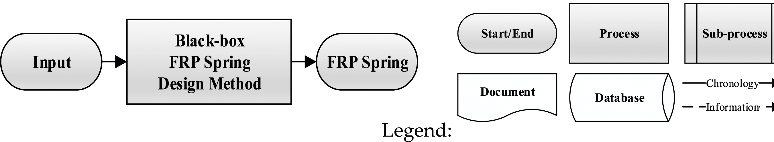
The essential problem of the current state is that there are only special solutions for specific applications. These considerations are not comprehensive enough when it comes to general FRP spring design, since, for example, the choice of material or the type of spring to be developed is already strongly preconstrained or fixed.
In order to concretize the black box with this research background, it has been subdivided into individual segments and specified by taking into account all relevant aspects. The FRP spring design can be divided into four main steps, as shown in Figure 2. First, the requirements must be sorted and prioritized and their effects on the material selection and/or properties must be determined. After the requirements management, the properties of possible spring types must be worked out and selection recommendations derived. Subdivision of the black box model into four main modules.
The next step is the determination of the FRP material. Based on the selected type of spring and material, an iterative preliminary design of the spring can be carried out using analytical relationships in order to determine the load values in the spring cross-section. In the same step, the laminate properties to be expected must be calculated (e.g., using VDI 2014/CLT) and an evaluation must be made as a proof of strength.
Optionally, an FE analysis follows before the spring has to be manufactured and evaluated in tests. The method is completed by mathematical and experimental proof of function and strength. From the current point of view, both should always be carried out so that a comparison of the calculation results with the experimental results can be made at the verification point.
Verification by means of tests is indispensable in the development of FRP components. Characteristic values from the literature or from data sheets should only be used for predictions. This means that static, long-term, and cyclic tests are of great importance but also environmental influences must be taken into account. This is accompanied by producibility aspects, where available or feasible manufacturing options must be considered, which have a significant influence on the component properties. In this way, an FRP spring material and test database can be built up that contains real characteristic values. Indirectly, the manufacturing possibilities also influence the requirements profile, whereby the economic aspects in particular have to be regarded in addition to the technical properties. Particularly from the verification step, there is also a feedback path of results and findings to upstream steps.
The result of the examination is a general framework and flow chart for the design of FRP springs. In the following, the steps are detailed by analyzing the influencing and result variables.
Detailing the design steps
The elaboration of the main steps first requires knowledge of the input variables. Typical spring-related requirements were therefore categorized and specified. The requirements are related to the FRP properties, features, and other aspects, which are summarized in Figure 3. The aim of requirements management is to prioritize and include the important parameters in the FRP spring design method. Overview of requirements and FRP features for the requirements management step.
Based on the clarified input, the FRP spring type selection step follows. The direction of movement, the construction space, and the interfaces are primarily responsible for the selection of a suitable spring type. Subsequently, a comparative evaluation of the filtered spring types is possible with regards to geometrical complexity and producibility.
After a spring type has been selected, the FRP material has to be determined. An objective assessment must be made, based on relevant criteria and weighting, as well as a preselection of possible fiber/matrix components. A calculation of FRP properties for all possible combinations is made, on which an evaluation can be based.
With recommendations for spring type and FRP material, a preliminary calculation can be implemented with analytical models. In addition, a numerical simulation of the design is recommended but not necessary. An iterative improvement of the design or even the choice of material can be made. If no suitable design is possible, the spring type can also be questioned. Finally, the necessary evidence must be provided so that a production of test springs can be carried out.
Building on the previous structure plan in Figure 2, the modules were specified with spring-related aspects from Figure 3. The extended schedule is shown in Figure 4. Detailed workflow for the FRP spring design method.
Application of the spring method for a mountain bike rear suspension
Requirements management
The method should be validated by developing a prototype for a mountain bike rear suspension. First, a system analysis was carried out in order to draw up the list of requirements as an information supply for the requirements management. Two types of springs are used in bicycle chassis, the air spring and the steel spring. Steel springs used to be standard, but they have been superseded by the lighter and more adjustable air spring in many bicycle sectors, especially for cross-country mountain bikes. However, the air springs are also more vulnerable and less suitable for large spring deflections, especially in the event of hard impacts, for example, during a landing, as they have numerous seals. Moreover, their responsiveness (preload) is not as sensitive.
If robustness is a priority or the rider is heavier, steel springs are recommended. These consist of a cylindrical helical compression spring made of spring steel and a damper unit with pressure compensation reservoir. By changing the spring (rate), the system can be adapted to the rider and the terrain. The preload force can be adjusted by the initial spring length via a screw thread.
The test vehicle was a professional full suspension trail mountain bike Cannondale Habit® 3 with standard Fox air suspension, as shown in Figure 5(a). The air suspension was replaced by a comparable metal spring–damper unit in which the spring could to be exchanged by an FRP spring. Therefore, a DNM RCP-2S was used (Figure 5(b)). (a) Full suspension trail mountain bike Cannondale Habit 3. (b) Replacement damping unit 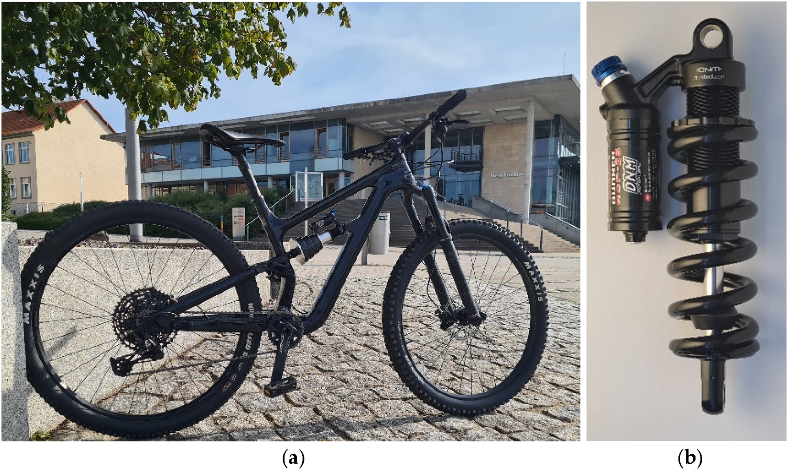
First, comparisons of the driving behavior were carried out with different steel springs in order to determine the right choice for the test driver. The targeted spring rate is
Filtered and categorized requirements for substituting of the metal spring by an FRP spring.

FRP spring type selection
In the field of metal springs, there are various types of springs that can be considered for an FRP material substitution. Furthermore, some types of FRP springs are known from the state of the art that are not made of metal yet. In order to be able to make a comparative assessment and derive selection recommendations, our own practical experience was gathered first. At this point, the manufacturing possibilities are of decisive importance.
Overview for the selection of FRP springs developed on the basis of publications and own practical investigations and derived evaluation standards.

For the bicycle application, a filtering is first carried out via the effective movement (linear), after which the spring nos. 1–16 remain. Regarding the installation boundaries (inner piston rod, pressure vessel, and cylindrical shape for easy installation in any position) and the planned deflection, spring nos. 6 (as stack), 8, 9 (as stack), 10, 11, 13, and 15 (as stack) can be further considered. Stackups of springs require construction considerations, which increases the assembly complexity which is not in the sense of a rough application like the bicycle application. The spring Nos. 8, 10, 11, and 13 remain. Focusing on material utilization, tension and torsion loads are preferred over bending loads. Additionally, the stress distribution in 13 is superimposed.
Finally, compression springs (10) and volute springs (11) show their suitability, which is why the complexity and producibility now have to be compared. Thereupon, the volute spring appears as the best choice with regards to the given conditions. On the basis of these considerations, the research group decided early on to investigate this type of spring more closely so that corresponding experiences were available.
Although the metal volute spring is only found in a few applications today, it seemed ideal for an FRP implementation. Until the work by the authors, for example, published in References 36–38, no FRP volute springs had been considered by others. The use of flat semi-finished fiber products and a winding technique favors modern implementation. In addition, the layered structure offers the potential for customized solutions with local adjustments of layer thicknesses, orientations, sandwich structures, or multi-material design. Thus, the volute spring was selected for the concretization of the spring design method and to test and validate it with an application of high novelty value.
FRP material selection
Material selection is an essential module of the FRP spring design method, since compliance with the requirements is largely defined by the choice of the material components fibers and matrix. A detailed expose on this subject regarding FRP springs has been published as “Material Selection Method for Composite Springs” in Reference 39 by the authors. Therein, an evaluation of all possible fiber–matrix combinations is conducted and prepared as a selection recommendation by means of ranking. Based on the requirements profiles for FRP material properties and systems integration, the criteria and weighting could be derived in order to evaluate possible materials. In the present work, this method was used with the condensed input of Table 1. The theoretical evaluation leads to the recommendation of carbon fibers (ToraycaTM T300, Toray Industries, Inc., Tokyo, Japan) with a matrix of epoxy resin representing the first choice for the bike application. This combination offers high fatigue resistance, high G-modulus, and also meets all other required properties.
FRP volute spring calculation
The volute spring, also called evolute spring, conical spring, or buffer spring, is a compression spring with a conical shell shape made of coiled tape material, which is loaded with torsion during axial compression.
1
The volute spring was an ideal buffer for heavy rail vehicles.
39
It can also be used as a so-called double volute spring, in which the shape is mirrored at the larger end.
40
Despite its compact design, it can absorb large forces and dissipate impact energy, as friction occurs between the coils. In addition, it has built-in overload protection, as the coils are applied to the spring plates during deflection, which results in a progressive force characteristic. Over time, the buffer spring has been superseded by other types of springs or assemblies, for example, the friction ring spring or coil spring–damper units, which offer more adjustment possibilities for the damping characteristics. Today, their use is limited to undercarriages and buffers on wagons (e.g., mine railways), heavy-duty vehicles and crane systems (end or emergency stops), and for locks in hydraulic engineering. They are used in scissors/grippers to prevent finger crushing,
40
as tablecloth clamps (buckling safety), and for damping in buildings. As previously described, the authors appear to have done the first research towards converting this particular spring type into an FRP spring. An example is shown in Figure 6. CFRP volute springs, manufactured and characterized by the authors.
The FRP tape is spirally wound around an inner cylinder (number of active coils 
Regarding the spring parameters, the rectangular cross-section has a width 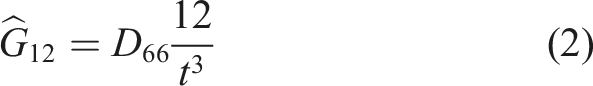
The combination of moduli
Another important fact to consider is the space spiral, which possesses a variable radius, determining the midline of the rectangular cross-section. Each coil has a different radius and a different contribution to the spring rate. The analytical spring model, where formula (1) is part of, does in fact considers this variable radius rKx by segmentation with a run variable 
Additionally, the progression of the curve is carried out via this segmentation, since the end coils continuously lie against the plates, increasing the spring’s stiffness.
Usual metal springs have the circular or nearly quadratic cross-section. The wire twists with the negligible bending. For the volute spring, one can expect due to very thin cross-section, that other effects can dominate the stress–strain state. Therefore, numerical simulations in Ansys Composite PrepPost (ACP) (Ansys Inc., Canonsburg, Pennsylvania) were carried out. Figure 7(a) shows the principal stresses of the outer layer, which approve the predominantly twist character of the material in the direction of the axis of the cross-section and justify the usage of formula (1). (a) Numerical analysis in Ansys ACP, considering the principal stresses that validate the twisting character of the cross-section. (b) Model of the unloaded installation situation of the preliminary design.
Since the tape is subjected to torsional load, the fibers are (according to the principal stresses) ideally positioned at ± 45° to the longitudinal direction of the tape, but any other layup, orientation, or even sandwich structures are possible.
The authors developed an Excel tool 44 that varies all geometry parameters to fit the spring characteristics to a target working point, taking into account the limits of the construction area. The Excel solver is used to find the geometry for which the weight is minimal. After the preliminary design, a comparative calculation of the characteristic curve was carried out by means of numerical simulation in Ansys ACP, which is an additional but not mandatory step in the method. Figure 7(b) shows the spring–damper assembly of the mountain bike with the suitable spring design in the unloaded installation situation.
To further investigate the FRP characteristics, the FE simulations were used to evaluate stresses and strains in Figure 8(a), as well as strength results in form of the Inter-Fiber-Failure-(IFF) Criterion according to Puck in Figure 8(b). Sufficient reserves of the CFRP could be shown for the static load case, since the failure criterion reaches 0.75 in the middle of the spring. The outer coil has a realistic contact with friction, whereas the edge of the spring is able to lift up from the plate. The stress concentration on the inner coil is caused by the fixed boundary condition that was used to stabilize the simulation convergence. (a) Stress–strain evaluation depending on the spring deflection. (b) FE-simulation in Ansys ACP as validation with IFF-Criterion according to Puck (figures by authors).
Practical experiments
Laboratory tests
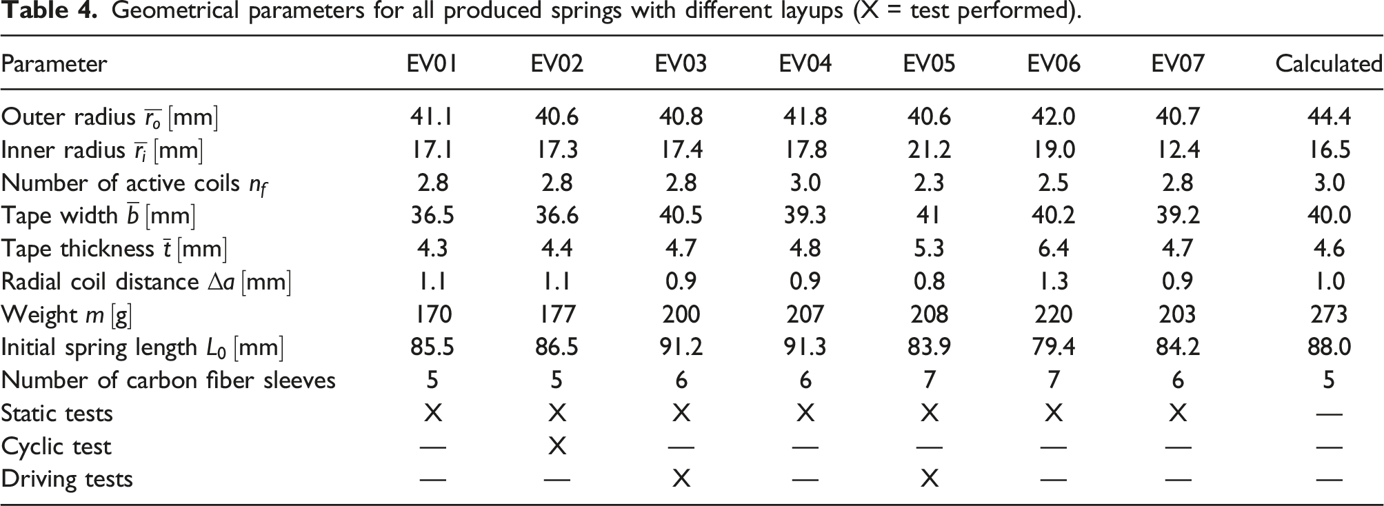
The practical experiments were subdivided into considerations for tapes and springs, which is a general approach in the research group in order to gain a better understanding of the spring. Results for the tape analyses were published by the authors in Reference 38. Here, the spring investigations are focused. The general production method was presented in Reference 37. Based on this technique, the preliminary spring design consists of 5–7 braided carbon fiber sleeves (Carbon-Werke Weißgerber GmbH, Type KB-4025 with 6k rovings; 400 tex; 3,30 €/m, Wallerstein, Germany) which are layered flat. The inner spring geometry is defined by a 3D-printed core that supports the tape winding process. After the resin is cured, the core has to be removed and spring ends have to be trimmed by a saw and finished, for example, with a grinding table, to stand straight on the spring plates. Figure 8(a) shows such a finished volute spring. In Figure 9(b) a dislocation of the tape occurs, if inadequate tension is applied during winding. Figure 9(c) shows possible imperfections through air voids. (a) Finished CFRP volute spring; (b) distortion of inner tape surface; (c) air voids in tape cross-section (pictures by authors).
Fiber volume content determination by thermal decomposition.

Geometrical parameters for all produced springs with different layups (X = test performed).
The main function of the springs can be evaluated using the (a) Characteristic curves for all manufactured springs; (b) comparison of calculated and measured characteristic F(s)-curves for EV03 with a decent agreement (diagrams by authors).
Figure 10(b) compares the characteristic curve of EV03 with a decent agreement to the metal spring counterpart as well as analytical and numerical calculations for the CFRP spring. For a deflection of s = 40 mm, EV03 indicates ΔF ≈ +150 N (5.6%), which is increasing to ΔF ≈ +570 N (18%) for maximum deflection s = 47 mm. Considering the real progression compared to the linear target curve, this deviation is as expected.
A fatigue test was carried out before the test rides started. EV02 was therefore tested on a servo-hydraulic machine, as it had the best production quality of all sample springs in order to reduce the influence of manufacturing deviations as much as possible. Usually, a load spectrum is specified that is similar to the loads in practical scenarios, but such a spectrum was not available for this specific application. Instead, an amplitude of s = 47 𝑚𝑚 and a frequency of f = 6 Hz were chosen (at room temperature). This amplitude corresponds to the maximum possible suspension deflection in the Cannondale Habit 3. Such load is not or very rare to be expected in real bicycle use, which ensures that the fatigue life is not overestimated by this test. Looking at Figure 8(a), the FE-simulation predicts a strain of ε‖ = 0.8..1.0 % for maximum deflection, which is in fact a challenging range for fatigue considerations.
Since the coil distance is short, the spring was greased to reduce friction effects. In order to observe the behavior of the spring, the F(s)-curve was recorded before the test as well as for N = 104, 2∙104, and 2.5∙104 load cycles, for which the spring was finally removed from the cyclic test machine. As shown in Figure 11(a), the usable spring deflection decreases by continued load cycles due to smaller defects (comparable with dynamic relaxation effects in metal springs). Because of this, the spring rate decreases as well, beginning at c = 37 N/mm and falling to c = 27 N/mm (≈-27%) after the test. Since the maximum spring force is still achieved, it can be assumed that only IFF and less fiber failures (FFs) are present. These cause an increase in both internal friction and friction between coils (oblique deflection), leading to an increase of the hysteresis. Continuing the test run, smaller cracks could be detected in the middle section of the spring, validating the interpretation above. Finally, the test was completed after N = 2.5∙104 load cycles due to the increase of the failure (Figure 8(b)). Comparing this endurance with Reference 45 (p. 227), the expected fatigue life of [0/90]s HTS-carbon for 1% strain is about N = 104, which confirms the established fatigue behavior. (a) Dependence of spring characteristics on number of load cycles 
To gain a better understanding of the fatigue area, the spring was cut after the tests, to have a closer look on the inner side of the coil segment (Figure 8(c) and (d)). It becomes clear that the fracture is located on a manufacturing distortion on the inner side of the coil segment, initiating the crack. Through the continued test run, the crack grew diagonally, along the fiber direction over the tape width. Given this clear failure situation, no further investigations with higher resolution imaging, for example, microscopy, SEM were carried out.
The insightful practical fatigue experiment can be concluded in major findings: - Using the self-developed Excel tool, a suitable spring could be found for the given boundary conditions, in order to substitute the metal spring. - The predicted spring characteristic is in a good agreement with measurements, regarding the carefully chosen parameters for the analytical approach as well as the numerical analysis and validation. - The manufacturing process is difficult because of the winding technique of the wet FRP tape, leading to geometrical imperfections. - The distance between the coils was determined too small, leading to contact/friction and therefore wear and noises. This can be improved by increased spacing between the coils for future springs. - The non-given load spectrum had to be compensated by a very high load approach. - The spring rate decreases about 1/4, caused by fatigue failure processes. - The CFRP tape´s fatigue behavior is as expected from the literature, but fatigue performance should be carefully investigated for cyclic loaded springs as there may occur unforeseen effects. - Furthermore, the effect of shape memory polymer phenomena on recovery behavior was not investigated in this study but should be considered in future for more accurate result interpretations.
Driving tests
After the various preliminary tests, the CFRP volute spring was installed into the DNM RCP-2S (see Figure 5) using an aluminum adapter for length compensation and to prevent contact with the pressure vessel. The FRP spring weighs
The test rides were carried out by MTB professionals on MTB trails over a distance of 60 km (EV03) and 40 km (EV05). The suspension showed a fine response, caused by the progression and the high maximum force. This is particularly advantageous for mountain bikes, whose frame geometries require high spring rates in order to avoid overloading under heavy riding and especially impact loads. Compared to the frequently used steel springs, this shows a clear benefit. EV05 was favored during the test rides due to its higher spring rate. However, the thicker carbon tape rather causes coil contacts. To prevent further issues and to additionally minimize friction noises, the spring was lubricated. Rain and mud proved to be challenging for this spring type, as deposits can accumulate in the distance between coils. Nevertheless, spring function was ensured continuously.
Based on calculations and simulations, a preliminary proof of function could be provided. Additionally, the production method and design parameters could be further developed by means of practical tests and optimization potential was revealed.
Summary
In this manuscript, the research background concerning FRP composites as well as springs made out of these materials introduced the research field. Based on the findings, the main issue was pointed out, as there is no holistic FRP spring design method, considering all relevant factors. Using publications and numerous own studies, a new method for FRP spring design was developed. Therefore, a black box was segmented into essential steps, followed by further concretization of each process step. The method was further concretized and verified using the application of a mountain bike rear suspension. A requirement profile was defined for the bicycle, and the spring tape and material selection were carried out and enabled preliminary spring calculations. After validating numerically (ANSYS ACP), the targeted CFRP volute spring was manufactured and tested in static and cyclic laboratory tests. Driving tests not only confirmed the suitability of the spring but also revealed topics for further investigations.
A major finding of the study is recommendations for FRP composite spring designers, especially regarding requirements management and spring type selection. Furthermore, some spring-specific findings can be pointed out: the CFRP lightweight volute spring weighs only half of a comparable metal spring. The experiments disclosed a lower spring rate than theoretically expected as well as a loss of stiffness of the spring of about 25% after 25,000 full deflections just before failure. Downhill riding tests showed comparable driving characteristics as when using conventional steel springs. Due to production deviations, caused by the manufacturing process and shape complexity, the ascertained static material properties were lower than theoretically expected, which had been (over)compensated by extending the FRP layup. The conflicting requirements of installation space and spring diameter, and therefore also the coil spacing and coil contact, are challenging.
An improvement could be made through partially automatization of the winding process and resin infusion or PrePreg techniques to ensure better reproducibility.
Conclusion
In conclusion, the design and development of fiber-reinforced polymer composite springs was not yet systematically considered, especially taking the entire design process into account. Through detailed research and analysis of the state of the art in this field, we developed a new design method on a scientific basis. The innovation of our study is that we included all relevant aspects in a methodical design process regarding both composite parts as well as spring specific demands, which has previously been a problem in fiber composite spring design. The second innovation of this contribution and its related studies is the comprehensive view on the FRP volute spring, which was not done by others so far, and demonstrated the suitability with an experimental study on a mountain bike suspension.
Moving forward, further testing and refinement of the design for each spring type will be necessary to fully understand the performance characteristics and potential limitations of the fiber composite springs. Economic aspects should be considered for possible serial productions in order to assess the competitiveness of FRP springs for concrete boundary and business conditions.
Overall, the potential for fiber composite materials to revolutionize traditional spring design is an exciting prospect, and we look forward to continuing our research and development in this area. The research is a contribution for FRP spring design considerations as well as to extend the range of applications for FRP springs in the future.
Footnotes
Acknowledgments
Declaration of conflicting interests
The author(s) declared no potential conflicts of interest with respect to the research, authorship, and/or publication of this article.
Funding
The author(s) disclosed receipt of the following financial support for the research, authorship, and/or publication of this article: The publication costs were funded by the Open Access Publication Fund of the Technische Universität Ilmenau.
Ethical approval
Data availability statement
Calculation data and further details are referenced at the respective sections.