
Abstract
Elastomeric bearings consist of alternating rubber and metal spacer layers bonded via vulcanization technique. As important structural components in aerospace and bridge construction as well as other industries, the reliability of elastomeric bearings has a significant impact on the safety of the whole system. In this work, the finite element method is used to study the stress and displacement distributions of spherical laminated elastomeric bearings during helicopter flight, and then the theory of cumulative fatigue damage is used to analyze the fatigue lifetime of the bearing. By means of the comparative analysis of six single-load cases and a multiple-load case of the bearing categorized from the viewpoint of helicopter flight characteristics, the main influencing factors and how they affect the stress and displacement distributions are revealed. Finally, a durability test is conducted and the experimental results are well consistent with the calculated results, which indicates the prediction accuracy of the model. The work would be beneficial to the optimal design and reliable service of elastomeric bearings.
Introduction
Elastomeric bearings consist of alternating rubber and metal spacer layers bonded through vulcanization, which act as load-transmitting devices and accommodate deformations by the rubber layers. As a type of important structural components, they have been extensively applied in aerospace, bridge construction and other industries due to their high vibration damping characteristics,1–3 simple structure, long service life, and high reliability. Especially in helicopter rotor hubs, spherical laminated elastomeric bearings are used as hinges for flapping, lead-lag, and pitch motions of rotor blades. Therefore, they need to be robust to withstand huge forces while tolerating the motions during helicopter flight. 4
Qin et al. 5 used ANSYS Parametric Design Language (APDL) to analyze the stiffness and stresses of elastomeric bearings with different characteristic parameters and found the optimal characteristic parameters for elastomeric bearing design based on the results. Mohamedmeki et al. 6 provided the fatigue analysis of elastomeric bearing pads under compressive loads, and studied the relation among load, load frequencies, and fatigue lifetime through ABAQUS software and Fe-Safe tool. Kazeminezhad et al. 7 investigated the vertical stiffness of elastomeric bearings in the presence of rotation and lateral displacement using the finite element method (FEM). Chen et al. 1 used the FEM to study the mechanical behavior of elastomeric bearings. They obtained the stress distributions of rubber layers of elastomeric bearings and further analyzed the influences of thickness of rubber layers, shape of injection hole, and profile of elastomeric bearings on the stress distributions. Chen et al. 8 derived the formulas of compression rigidity and torsion rigidity of rubber layers of spherical laminated elastomeric bearings, and developed a computational model of equivalent rigidity of the compression rigidity and the torsion rigidity. The results showed that the use of equivalent rigidity could obviously eliminate the rigidity difference between different rubber layers. Wang and Liu 9 introduced a set of methods for stiffness calculation of cylindrical and conical elastomeric bearings of the hingeless model rotor, and the validity of the methods were demonstrated by comparing the calculated results with the test results. Zhu et al. 10 conducted the full-scale tests to investigate the horizontal mechanical behavior of elastomeric bearings subjected to eccentric vertical loading, and a mechanical behavior prediction model was developed based on the test data and the Koh-Kelly model. Kalfas et al. 11 used ABAQUS for analyzing the stresses of elastomeric bearings under cyclic shear and variable axial loads. Sun 12 provided a parameterized finite element modeling method for elastomeric bearings by secondary development of ABAQUS with Python. Liu and Yu 13 analyzed the influence of meshing method on the numerical convergence in ABAQUS and concluded that the coarse mesh of rubber layers improved the convergence but caused the increase of the simulated stiffness of elastomeric bearings.
It can be seen that though elastomeric bearings have been widely employed as important structural components and their reliability significantly affects the safety of the whole structural system, there are seldom systematic or comprehensive researches on the strength and durability of elastomeric bearings under multiple loads, especially on the stress and displacement distributions as well as the fatigue lifetime of spherical laminated elastomeric bearings during helicopter flight.
In this work, the finite element method is used to study the stress and displacement distributions of spherical laminated elastomeric bearings during helicopter flight, and then the theory of cumulative fatigue damage is used to analyze the fatigue lifetime of the bearing.
Modeling methods
Finite element model of spherical laminated elastomeric bearing
Figure 1 shows a prototype of the spherical laminated elastomeric bearing consisting of a small metallic member, rubber layers, metal spacer layers, and a large metallic member. Note that a central hole passes through the small metallic member and the metal spacer layers, which is filled with the rubber. According to the practical experience in engineering, the deformations of both the metallic members are much smaller than those of metal spacer and rubber layers. Therefore, the rubber and metal spacer layers are taken into account while neglecting the two metallic members for simplicity in the finite element (FE) model of the bearing. Schematic of a spherical laminated elastomeric bearing.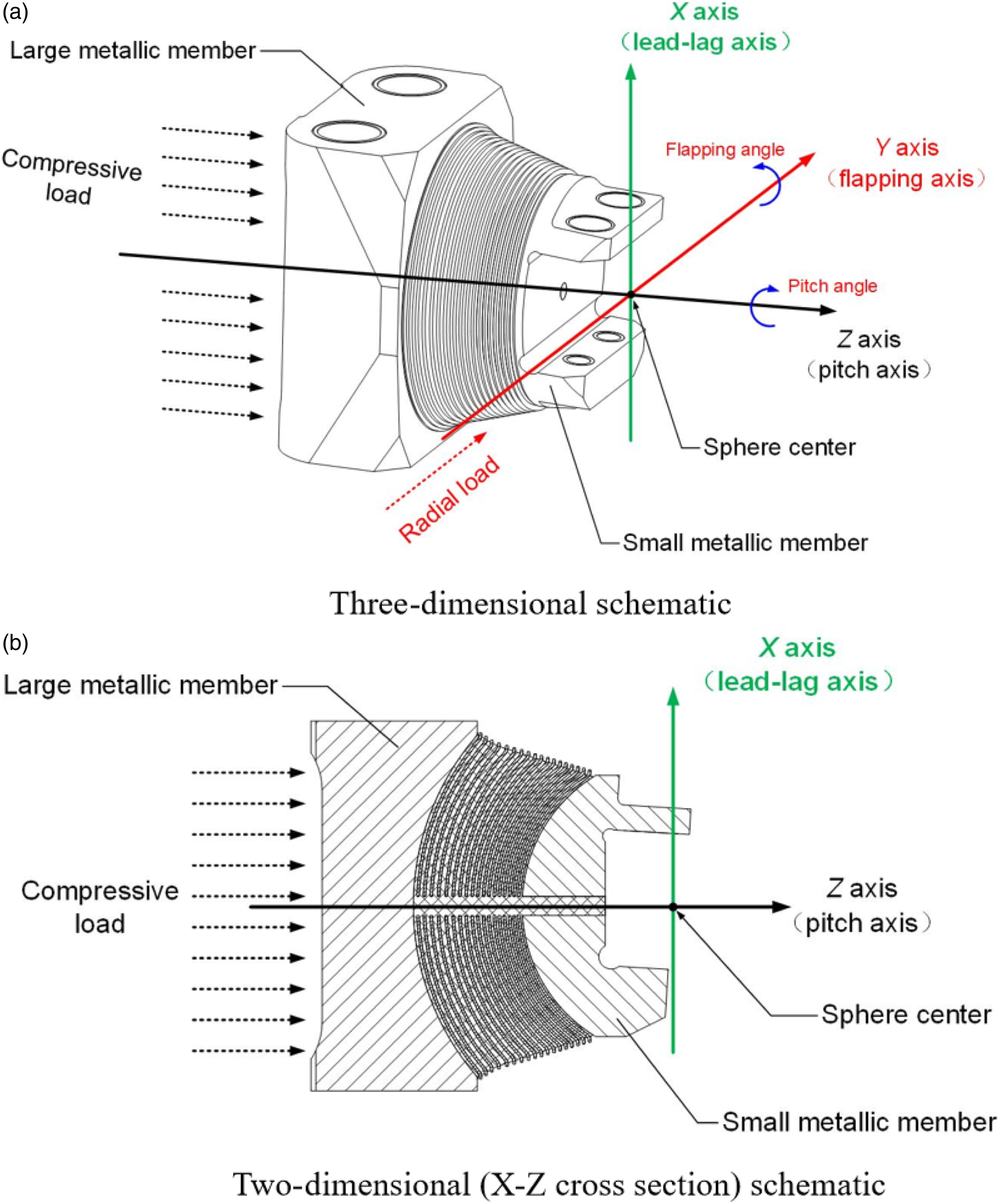
As shown in Figure 2, there are 19 layers of rubber in total, and the thickness of each rubber layer is listed in Table 1. Among the rubber layers, the 1st and the 19th layers are closest to the small metallic member and the large metallic member respectively. The total number of metal spacer layers is 18, and the thickness of each metal spacer layer is 0.8 mm. Finite element model of rubber and metal spacer layers of the bearing, where the rubber components including the rubber layers and the central hole filled with rubber are colored by gray, and the metal spacer layers are colored by blue. Thickness of rubber layers in the finite element model.


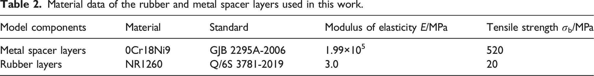
Material data of the rubber and metal spacer layers used in this work.
In this work, the parameters of the Mooney-Rivlin model were obtained by conducting uniaxial tensile tests and fitting experimental data.20–22 For the natural rubber used in this paper, the values of C10 and C1 were 0.123 MPa and 0.501 MPa, respectively.
Due to the significant differences in material properties between rubber and metal spacer layers, the mesh types of rubber layer and metal spacer layer are different. In this study, the metal spacer layer of the bearing adopts the mesh type of C3D8R, which is an 8-node linear brick with reduced integration and hourglass control characteristics, being a common mesh type of linear elastic materials. The rubber layer of the bearing adopts the mesh type of C3D8RH, which is an 8-node linear hybrid brick with such characteristics as constant pressure, reduced integration, and hourglass control. Now the mesh type of C3D8RH is often used for describing the mechanical behavior of rubber with hyperelastic characteristic. 23
Fine meshes are built for the regions around the central hole of metal spacer layers to avoid convergence problems caused by stress concentration. There are a total of 255,488 elements in the FE model, including 127,616 elements of rubber layers and 127,872 elements of metal spacer layers.
The above-mentioned geometric model, the physical structure and dimension, the material properties and the meshing method are used to construct the finite element model of the spherical laminated elastomeric bearing, and then the following mechanical boundary conditions are defined to carry out the finite element analysis.
Analytical model for strength
When numerically analyzing the strength of spherical laminated elastomeric bearings during helicopter flight, due to the distinct material properties of rubber and metal spacer layers, the rubber layers undergo significant deformation while the metal spacer layers bear the stress for ensuring the reliability of the bearing. Therefore, the following basic assumptions are adopted. (1) The metal spacers maintain the spherical shape since the rubber layers undergo significant deformation during the loading process. (2) According to the above-mentioned Mooney–Rivlin model, the rubber layers are homogeneous and isotropic.
24
(3) Since the rubber layer and the metal spacer layer are firmly bonded via vulcanization technique, there is no relative slip on the contact interface.
1
(4) The changes of thickness and surface area of rubber layers caused by the pitch load are ignored.
1
(5) The compressive and shear deformation behaviors of rubber layers obey Hooke’s law.
8
According to the helicopter flight characteristics, the loading conditions for the bearing are categorized into six single-load cases and a multiple-load case. In order to reveal the main influencing factors and how they affect the stress and displacement distributions of the bearing during helicopter flight, the comparative analysis of all the six single-load cases and the multiple-load case of the bearing is performed.
Single-load cases
Load data of the elastomeric bearing in single-load cases.

The upper and lower ends of the elastic bearing shown in Figure 2 are connected to the small metallic member and the large metallic member, respectively. The large metallic member is directly fixed to the helicopter rotor hub during the service process, while the small metallic member is directly connected to the helicopter rotor blades. Consequently, the mechanical boundary conditions are applied to the interface between the small metallic member and the rubber layer, while the interface between the large metallic member and the rubber layer is always fixed.25–27
Multiple-load case
In the multiple-load case, the load of the elastomeric bearing was a combination of that of the single-load cases, including (A) the radial load of 20,184 N in the positive direction of Y-axis, (B) the compressive load of 189,495 N in Z-axis direction, (C+E) the dynamic (0.076 rad) and the static (0.012 rad) flapping loads rotating about Y-axis, and (D+F) the dynamic (0.132 rad) and the static (0.073 rad) pitch loads rotating about Z-axis. All the loads were applied to the interface between the small metallic member and the rubber layer. The interface between the large metallic member and the rubber layer was fixed.
Analytical model for durability
According to the specific design requirement of the hinge in helicopter rotor hubs, the average loading frequency of the bearing is 4 Hz, and the fatigue loading duration of the bearing is 1000 h. Therefore, the number of the fatigue loading cycles (i.e. the required fatigue lifetime) of the bearing is required to be 1000 × 3600 × 4=1.44×10⁷.
The fatigue analysis in this work is mainly based on the theory of cumulative fatigue damage, 28 and the number of the fatigue loading cycles of the bearing is verified by means of FOS (Factor of strength). 29 When inputting the target lifetime of the bearing in fatigue analysis software, the corresponding FOS will be obtained. If the minimum FOS of the bearing is larger than 1, namely all the FOS values of the bearing are larger than 1, the bearing can achieve the input target lifetime, which also means that the actual lifetime of the bearing is equal to the product of the minimum FOS and the input target lifetime.
In order to ensure the rationality and accuracy of fatigue calculation, the basic material properties assigned to the finite element model of strength were used as the input material properties for the fatigue analysis. Meanwhile, only the stresses and strains in the initial and last load steps were set for the load dataset of the bearing in order to simplify the calculation. 30
Results and discussion of strength calculation
Stress and displacement distributions in single-load cases
In strength analysis of mechanical structures, the basic method to determine whether a structure has failed is to compare the maximum von-Mises stress of the structure during the loading process with the failure strength obtained through uniaxial tensile experiments. If the maximum von-Mises stress reaches the failure strength, the structure can be determined to have failed. The tensile strength obtained from uniaxial tensile tests of the metal spacer and rubber material used in the elastomeric bearing is listed in Table 2.
Stress and displacement contours of the rubber and metal spacer layers under radial load.


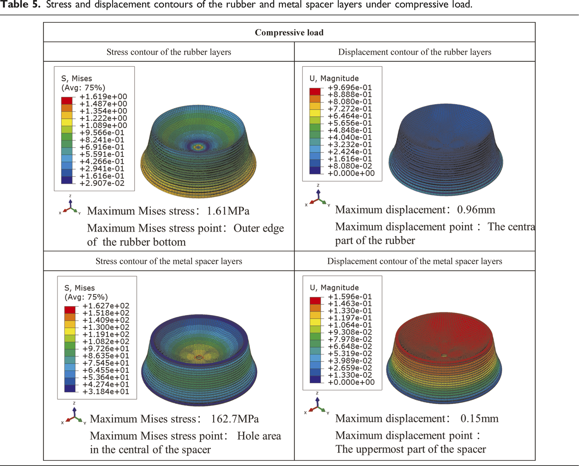
Stress and displacement contours of the rubber and metal spacer layers under compressive load.

Stress and displacement contours of the rubber and metal spacer layers under dynamic flapping load.


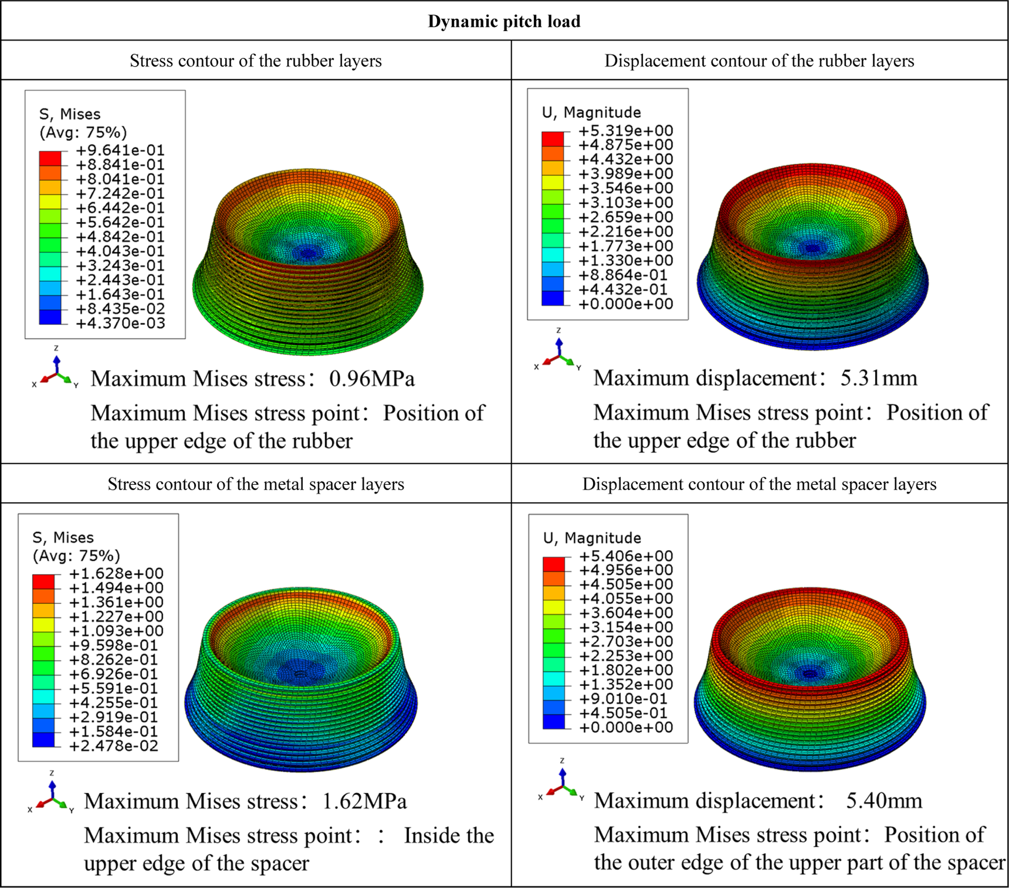
Stress and displacement contours of the rubber and metal spacer layers under dynamic pitch load.

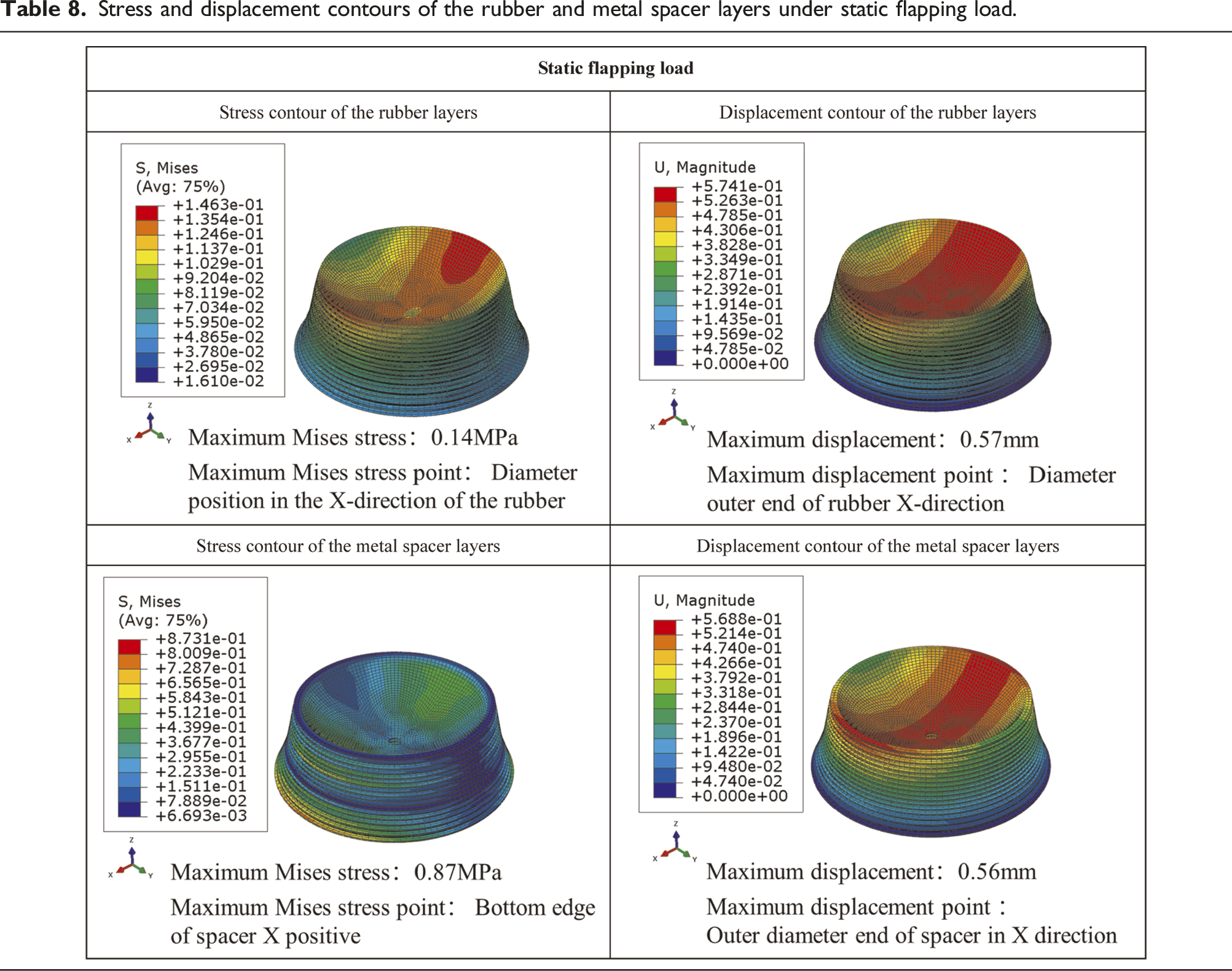
Stress and displacement contours of the rubber and metal spacer layers under static flapping load.

Stress and displacement contours of the rubber and metal spacer layers under static pitch load.


Stress and displacement distributions in multiple-load case
The displacement contours of the elastomeric bearing under multiple-load condition are shown in Figure 3. Figure 3(a) presents that the maximum displacement is located at the outer edge of the top layer in the positive direction of Y-axis, which is 7.4 mm. It can be inferred that the maximum displacement is mainly caused by the flapping load and the pitch load by means of comparing the displacement contours listed in Tables 4–9 with the displacement contours shown in Figure 3. The displacement distributions between the 15th and 37th layers (i.e. the lower part of rubber and metal spacer layers) under dynamic flapping load (Table 6) or dynamic pitch load (Table 7) are basically similar to those in Figure 3(a). On the other hand, the flapping load and the pitch load in counter-clockwise direction were simultaneously applied to the model shown in Figure 3. If the displacement contours presented in Tables 6 and 7 are combined, then the maximum and minimum displacements occur at the upper edge of the bearing in the positive direction and the negative direction of Y-axis, respectively, which is similar to the distributions shown in Figure 3(a). This is because that the combination of displacements in the positive direction of Y-axis is in a constructive way while the combination in the negative direction of Y-axis is in a destructive way. Displacement contour of the elastomeric bearing under multiple loads.
As portrayed in Figure 3(b), the maximum displacement in the positive direction of X-axis (3.59 mm) occurs at the outer edge of the top layer in the negative direction of Y-axis, and the maximum displacement in the negative direction of X-axis (7.33 mm) can be observed at the outer edge of the top layer in the positive direction of Y-axis. This is because of the following three reasons. (1) If there is only a single dynamic or static pitch load in counter-clockwise direction, the contours of displacement magnitude of rubber and metal spacer layers are the same as those listed in Table 7 or Table 9, and the displacement distributions in X-axis direction are almost symmetric about the X-Z coordinate plane, which means that the displacement values are approximately equal in magnitude but opposite in direction; (2) if there is only a single dynamic or static load flapping to the positive direction of X-axis whose central-axis is Y-axis, the displacement contours of rubber and metal spacer layers are the same as those listed in Table 6 or Table 8, and the displacement distributions in X-axis direction are numerically symmetric about the X-Z coordinate plane; (3) when the elastomeric bearing is under multiple loads, it suffers from both pitch and flapping loads at the same time, thus the absolute value of the displacement in the negative direction of X-axis (7.33 mm) is obviously larger than the one in the positive direction of X-axis (3.59 mm), and they are no longer symmetric about the X-Z coordinate plane.
In Figure 3(c), the displacement in the positive direction of Y-axis exhibits a maximum value (5.38 mm) at the outer edge of the top layer in the positive direction of X-axis, and the maximum displacement in the negative direction of Y-axis (5.44 mm) is observed at the outer edge of the top layer in the negative direction of X-axis. This is because that the displacement in Y-axis direction is mainly caused by the pitch load in counter-clockwise direction.
As shown in Figure 3(d), the displacement in the positive direction of Z-axis has a maximum value (2.96 mm) at the outer edge of the top layer in the negative direction of X-axis, and the maximum displacement (3.13 mm) in the negative direction of Z-axis is located at the outer edge of the top layer in the positive direction of X-axis. There are two reasons for this physical phenomenon. (1) The displacement in Z-axis direction is mainly affected by the flapping load whose central-axis is Y-axis, and the flapping motion is towards the positive direction of X-axis; (2) the direction of the compressive load is the same as the negative direction of Z-axis, thus the displacement in Z-axis direction is also affected by the compressive load.
The von-Mises stress contour of metal spacer layers under multiple loads is shown in Figure 4(a). The maximum von-Mises stress (170.7 MPa) is located between the 6th and 11th metal spacer layers and in the positive direction of Y-axis, which is lower than the material tensile strength of the metal spacer (520 MPa). And high stress concentration around the central holes of the first and last metal spacer layers is also observed. By means of comparing the von-Mises stress contours of metal spacer layers under various single-load conditions presented in Tables 4–9 with the one shown in Figure 4(a), it can be concluded that the von-Mises stress of the metal spacer layers under multiple loads is affected mainly by the radial load and the compressive load. The reasons for the physical phenomenon are analyzed as follows: (1) The highest von-Mises stress area (in the positive direction of Y-axis) shown in Figure 4(a) almost overlaps with the highest von-Mises stress area of metal spacer layers under the radial load listed in Table 4; (2) the von-Mises stress distributions around the central holes of the first and last metal spacer layers illustrated in Figure 4(a) are basically same as the corresponding von-Mises stress distributions under the compressive load listed in Table 5. Von-Mises stress contours of the metal spacer and rubber layers under multiple loads.
The von-Mises stress contour of rubber layers in the multiple-load case is exhibited in Figure 4(b). The maximum von-Mises stress (2.9 MPa) distributes between the 16th and 19th rubber layers and in the positive direction of Y-axis, which is less than the tensile strength of the rubber material (20 MPa). The highest von-Mises stress area shown in Figure 4(b) is basically consistent with the combination of the highest von-Mises stress areas of rubber layers listed in Tables 4 and 5. Especially, the summation of the maximum von-Mises stresses of rubber layers listed in Tables 4 and 5 (1.1 MPa+1.6 MPa=2.7 MPa) is approximately equal to the maximum von-Mises stress shown in Figure 4(b) (2.9 MPa). Therefore, based on the comparison of the von-Mises stress of rubber under various single-load cases listed in Tables 4–9 and the one shown in Figure 4(b), it can be concluded that the von-Mises stress of the rubber layers in the multiple-load case is mainly impacted by the radial load and the compressive load.
Results and discussion of durabilitycalculation
According to the above-mentioned results of the finite element simulation, the fatigue strength of the bearing under multiple loads was numerically calculated, as shown in Figure 5. It can be seen that the minimum factor of strength (FOS) is 1.051, namely the corresponding minimum fatigue lifetime of the bearing is 1.051 × 1.44×107=1.513 × 10⁷ cycles, meeting the durability requirement. Factor of strength of the elastomeric bearing under multiple loads.
Accordingly, durability experiments were conducted by means of a general-purpose fatigue testing machine with a set of homemade fixtures, which can impose the above-mentioned single load and multiple loads on the bearing. The experimental results indicate that the fatigue lifetime of the bearing is 1250 h, that is, 1.80×10⁷ cycles, when using “a ± 20% change in stiffness” as a fatigue failure criterion during the fatigue testing process. Therefore, the calculated result has good consistency with the result of the durability test.
The fatigue calculation results of the metal spacer and rubber layers of the bearing are demonstrated in Figure 6. It is shown in Figure 6(a) that the minimum FOS of metal spacer layers under cyclic fatigue load is 1.051. Consequently, according to the above-mentioned analytical model for durability, the metal spacer layers can avoid fatigue failure under the cyclic fatigue load in the duration of 1000 hours. It can be seen from Figure 6(b) that the minimum FOS of rubber layers under the cyclic fatigue load is 1.172, indicating that the rubber layers are able to avoid fatigue failure more efficiently than the metal spacer layers under the cyclic fatigue load in the duration. Factor of strength of the metal spacer and rubber layers under multiple loads.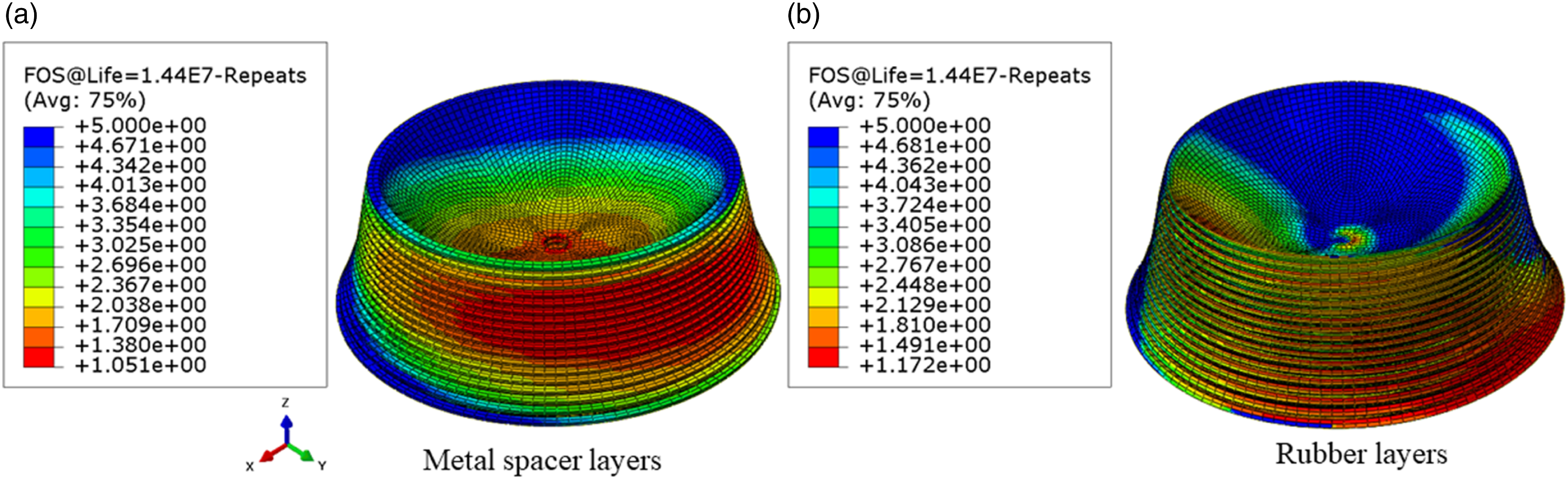
On the basis of the comparative analysis on the results in Figure 4 and 6, it is found that the highest von-Mises stress areas of the metal spacer layers (Figure 4(a)) and rubber layers (Figure 4(b)) overlap with the areas with the minimum FOS of the metal spacer layers (Figure 6(a)) and rubber layers (Figure 6(b)), respectively. This phenomenon can be explained by the theory of fatigue strength, especially the theory of cumulative fatigue damage. 28
Conclusions
In the multiple-load case, the maximum von-Mises stress (170.7 MPa) of the bearing distributes in metal spacer layers, while the maximum von-Mises stress of rubber layers is 2.9 MPa, which is mainly affected by the radial load and the compressive load. The maximum displacement of the bearing is 7.4 mm, which is mainly caused by the flapping load and the pitch load. The distributions of stress and displacement show that the bearing meets the strength requirements.
The minimum factor of strength of the bearing under cyclic fatigue loading condition is 1.051, meaning that the minimum fatigue lifetime of the bearing is 1.513×10⁷ cycles, which meets the durability requirements.
For the finite element analysis on the strength and durability of the bearing, the uncertainties in the input parameters exist not only in the finite element model but also in the mechanical boundary conditions. Therefore, the uncertainties in the input parameters need to be studied, and the variance-based sensitivity analyses need to be done in the future.31–34
Footnotes
Declaration of conflicting interests
The author(s) declared no potential conflicts of interest with respect to the research, authorship, and/or publication of this article.
Funding
The author(s) disclosed receipt of the following financial support for the research, authorship, and/or publication of this article: Key Research and Development Program of Shandong Province (Grant No. 2021ZLGX01).