
Abstract
Laser sintering (LS) enables cost-effective production of small batches as well as complex functional integration due to the direct build-up process without the need for specific tools. Further, geometrical restrictions are non-existent or only very limited. The combination of LS components with series components, for example, from injection molding (IM), allows to follow the growing trend of customizing and time tightening in the development process as well as the implementation of application-specific functions in small quantities. In order to exploit these potentials, reproducible and mechanically highly loadable joining processes are required for joining LS and IM components. Vibration welding represents a highly robust and stable process, which in this study is investigated for the production of LS-IM joints. Thereby, the focus is on the existing interactions between the two joining partners in the bonding zone. The investigations show that high bond strengths (in the area of the base materials) can be achieved by vibration welding. In contrast to other joining processes such as infrared welding, the bond quality is only marginally affected by the welding parameters. The characteristics of the weld seam are striking. While on the IM side a typical seam structure as known in the literature results, it deviates significantly for the LS side. Independent of the weld parameters, a highly oriented microstructure is recognizable that exhibits transcrystalline structures. In addition, less melt is generated and displaced into the weld bead for the LS component. Both aspects have been attributed to the different material properties of the joining partners.
Introduction
Additive manufacturing processes, such as laser sintering (LS), are characterized by the production of parts from single layers directly from a 3D model. 1 Compared to conventional methods, the direct build-up without specific tools enables a cost-effective production of small batches as well as complex functional integrations. 2 Furthermore, geometrical restrictions are non-existent or only very limited. The combination of these components with components from series production, for example, from injection molding (IM) processes, allows the growing trend of customization and time tightening in the development process to be followed as well as the implementation of application-specific functions in small quantities. To fully exploit these novel manufacturing concepts, reproducible and mechanically highly loadable joining processes are required for joining LS and IM components. For this reason, the production of LS-IM joints made of polyamide (PA) 12 using vibration welding will be investigated and the resulting joint properties will be fundamentally characterized within the scope of this study. The focus is on the interactions occurring in the bond zone.
Laser sintering
Laser sintering is a powder bed based additive manufacturing process. 3 Compared to subtractive processes, the layer-by-layer build-up allows complex geometries with low material demand. 1 The LS process can be divided into three steps: 4 Application of a powder layer via blade or roller, heating of the layer to the specific build temperature, melting of the component cross-section area by laser. Subsequently, the build platform is lowered and the three steps are repeated until the part is completed. 5 The build temperature is set to be between the crystallization temperature and the melting temperature of the semi-crystalline polymer. 6 The achievable strengths in the LS process are comparable to injection-molded parts. 2 However, the components exhibit increased porosity of 3–5%,7,8 an increased surface roughness 7 as well as higher crystallinity compared to IM components. These LS-specific properties can have an influence on the joining process and the resulting bond properties as shown for joints between LS components.9,10
Joining of LS parts
Previous studies have mainly focused on the bonding of LS components to each other. LS parts can be joined by means of cyanoacrylate adhesives. 11 According to Fieger, 12 achievable bond strengths of adhesively bonded LS components are about 6 N/mm2. By means of surface pretreatments or design elements, an increase in strength to approx. 11 N/mm2 can be achieved, 12 which, however, is still significantly below the base material strength of laser-sintered PA 12 components (45–50 N/mm2). For mechanical fasteners, the achievable strength is also in a very low range. In addition, the anisotropic component properties in the LS process weaken the resistance of the load-bearing elements. 13 In contrast, studies on welded LS parts show high achievable joint properties in the range of the base material strength, independent of the welding process. The energy input can take place via heat conduction in hot plate welding, 14 internal friction in ultrasonic welding, 9 external friction in vibration welding 10 as well as radiation-based in infrared welding. 10 The build-up direction in the LS process influences the ultrasonic as well as the infrared welding process. Due to the geometric shape of the energy director, which is dependent on the build-up direction, horizontal joining surfaces on the upper side of the component are preferable in the ultrasonic process. 9 In infrared welding, diagonally placed joining surfaces have to be avoided. 10 In contrast, the LS build-up direction shows only a negligible influence on the bond quality in the vibration welding process. 10
Studies on joints between LS and conventional components (e.g. by injection molding or extrusion) are very limited at the current stage. Studies on infrared welding show high achievable strengths also for LS-IM joints in the range of the PA 12 base material. 15 In addition to unreinforced IM components, joints can also be formed in combination with glass-fiber-reinforced components. Here, strengths in the range of the unreinforced LS components are achieved. 15 Thus, it can be stated that welding processes result in high bond qualities when joining LS components to each other as well as when joining LS with IM components.
Vibration welding
According to DIN 1910, the vibration welding process can be classified as a friction welding process. 16 The energy is generated by a friction relative movement of the joining partners to each other. 17 Compared to other welding processes, vibration welding is characterized by high process stability and short cycle times. 18 Also, absorption differences of the joining partners, as they occur, for example, for LS and IM components, show no effects on the joining process. The linear vibration welding process can be divided into four typical phases.17,18 In phase 1 (solid friction), the temperature in the joining zone increases until a thin melt film is formed. The melt film thickness increases in phase 2 until an equilibrium is reached between the energy introduced by vibration and the energy dissipating into the weld bead. This energy equilibrium results in a constant melt film thickness as well as a constant joining speed in phase 3, the quasi-steady melt flow. The achievement of this third phase is essential for a high weld quality and is a quality criterion in the vibration welding process. 19 Due to the energy equilibrium, a constant joining zone temperature above the melting temperature (semi-crystalline) or glass transition temperature (amorphous) of the material used is achieved in the third phase. For example, this temperature for polypropylene (PP) is up to 20 K 20 and for PA 66 up to 15 K 21 above the respective melting temperature. The level depends, among other things, on the process parameters amplitude and pressure.20,21 In phase 4, the vibration movement ends and cooling takes place.
Depending on the process and material, welded joints exhibit a typical seam morphology. Studies by Chung et al.
22
show for PA a weld seam consisting of deformed spherulites in the transition area to the base material, followed by a recrystallized zone and an optically amorphous zone, compare Figure 1. The recrystallized zone is most prominent for low welding pressures. The optically amorphous zone has no visible superstructures, but is crystalline, as shown by studies for PA6
22
and PA66.
23
In the transition zone to the base material, spherulites are only partially melted and oriented in flow direction of the squeeze flow. The thickness of the zone of deformed spherulites increases with increasing weld pressure.
24
During the flow of the melt into the weld bead, elongation processes occur, especially in the area of the joining plane, which can lead to high orientations. Morphological structure of a vibration weld seam of polyamide.
22

Materials and methods
Materials
The investigations were carried out with a semi-cyrystalline PA 12. For the LS components, a PA 12 fine powder of the type PA2200 (EOS GmbH, Germany, Krailling) was used. For the IM parts, the PA 12 type Vestamid L1901 (Evonik Industries AG, Germany, Essen) was used. Before the injection molding process, the material was dried at 80°C for 8 h.
Test specimens with dimensions of 70 mm × 51 mm × 4 mm were used to produce the vibration-welded joint. On the one hand, these were prepared from injection-molded plates by milling. The injection-molded plates were produced on a machine of the type 370 V Allrounder 800-315 (Arburg GmbH & Co. KG, Germany, Lossburg) according to the manufacturer’s specifications. On the other hand, the test specimens were produced directly by laser sintering on a Formiga P110 (EOS GmbH, Germany, Krailling) using the EOS standard parameters. Based on previous findings 10 that the build-up direction has only a negligible effect on the bond quality in vibration welding, the build-up direction was not varied. All LS components were placed vertically in the build chamber; the joining surface with the dimensions of 70 mm × 4 mm was positioned on the upper side of the component. After production, the test specimens were stored in a vacuum oven to prevent moisture absorption.
Characterization of joining partners
The joining partners were characterized with respect to their thermal, rheological and mechanical behavior. In addition, the microstructure was analyzed. Differential scanning calorimetry (DSC) investigations were carried out to evaluate the melting behavior and crystallinity. The measurements were carried out under a nitrogen atmosphere with a heating and cooling rate of 10 K/min using a DSC Q 1000 (TA Instruments, New Castle, USA). The samples of about 4 mg were taken from the joining zone of the specimens. The crystallinity was calculated according to equations (1), 209.3 J/g was used as the required energy for melting 100% crystalline PA 12 according to Gogolewski
25

The flow behavior of the specimens was analyzed by rotational viscometry using a viscometer of the type AR 2000 (TA Instruments, New Castle, US) on samples with a diameter of 25 mm at a frequency of 1 Hz, a load of 0.1% and a heating rate of 2 K/min. The evaluation of the microstructure of the specimens was carried out on 10-µm-thick thin sections by means of transmitted light microscopy in polarized light with a component position of 45° to the polarization direction. A microscope of the type Axio Imager.M2 (Karl Zeiss AG, Germany, Oberkochen) was used. The strength of the joining partners was determined on tensile bars of type 5A (taken from the specimens by milling), Figure 2(a), according to DIN ISO 527
26
with a repetition number of six. The tensile tests were carried out under standard conditions (23°C, 50% relative humidity
27
) at a test speed of 3 mm/min and a clamping length of 42 mm on a Zwick 1465 universal tensile testing machine (Zwick GmbH & Co.KG, Germany, Ulm). The specimens were dried to constant weight before the tensile tests. Semantical illustration of: (a) tensile bar dimensions according to DIN ISO 527
26
and (b) LS-IM butt joint.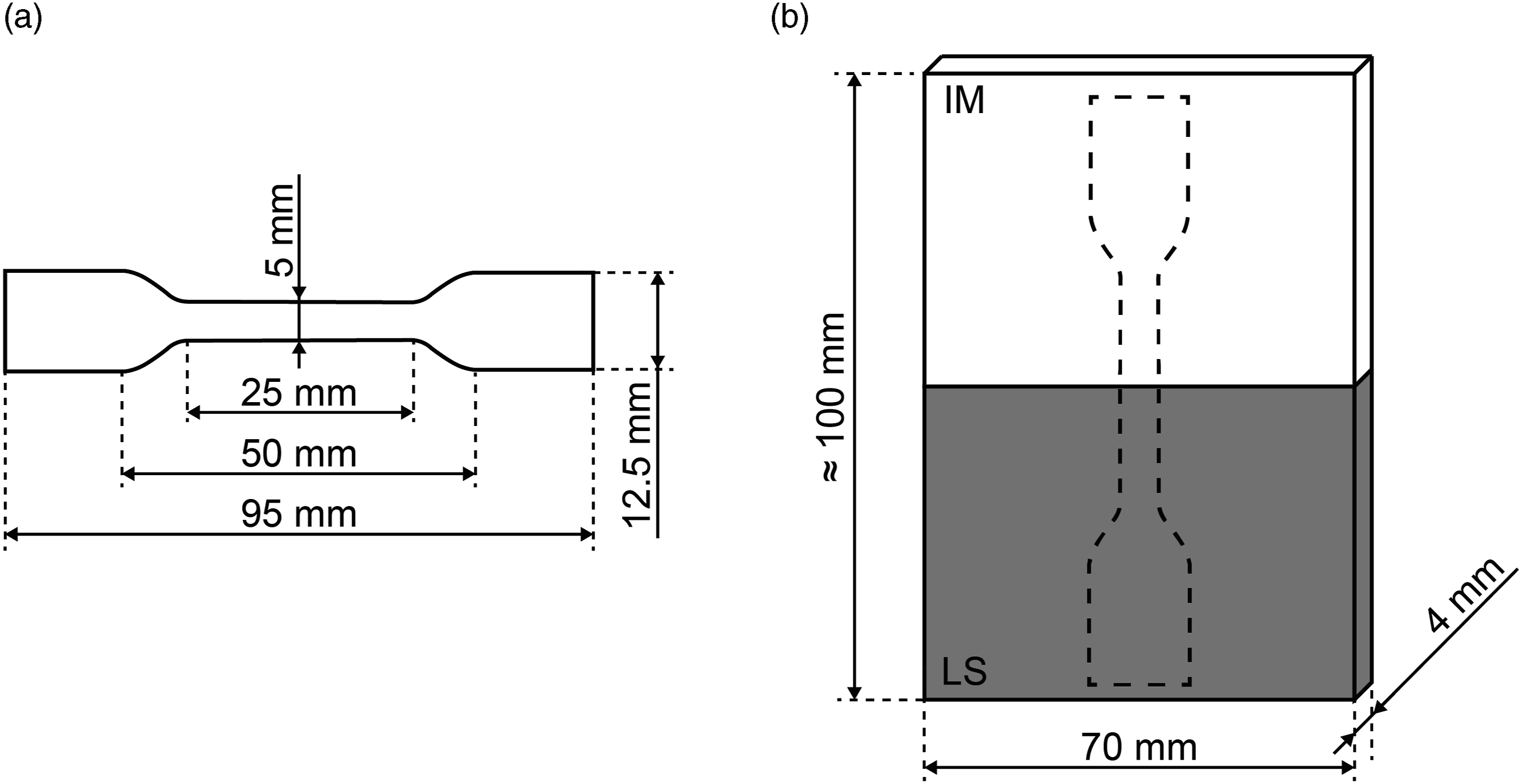
Vibration welding
Butt joints were produced by vibration welding between LS and IM components, Figure 2(b). A linear vibration laboratory welding machine of the type M-112 HR (Branson Ultraschall, Emerson Technology GmbH & Co. OHG, Germany, Dietzenbach) was used. The joining pressure was varied between 1.0 and 2.0 N/mm2 in 0.5 N/mm2 steps and the amplitude was varied between 0.7 and 0.9 mm. The weld path was 1.0 mm and the holding time 15 s for all variants. The frequency of the frictional relative movement between the joining partners was 235 Hz, whereby one partner performs the oscillating vibration movement while the second partner is fixed. To exclude any influence of the clamping position on the welding process due to the different joining partner properties (including stiffness, damping and flow behavior), it was kept constant for all trials.
Bond characterization
The bond between the LS and IM parts was characterized both optically and mechanically as a function of the vibration welding parameters. The weld seam characteristics were analyzed microscopically on thin sections with a thickness of 10 µm in polarized light with a component position of 45° using an Axio Imager.M2 microscope (Karl Zeiss AG, Germany, Oberkochen). For the evaluation of the bond strength tensile bars of type 5A,
26
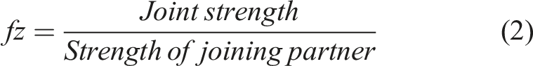
Figure 2(a), were taken from the butt joints by milling. Afterward, tensile tests were performed using a universal tensile machine of the type Zwick 1465 (Zwick GmbH & Co.KG, Germany, Ulm) with a test speed of 3 mm/min and a clamping length of 42 mm. For each parameter variation, nine tensile bars were tested. Before testing, the specimens were stored under vacuum to prevent moisture absorption. The maximum tensile strength and the achieved weld factor fz were evaluated in each case. The weld factor is calculated from the ratio of the bond strength to the strength of the joining partner, using equation (2)
Results and discussion
Joining partner characterization
The optical characterization of the microstructure for both the LS and IM component are shown in Figure 3. The injection-molded specimen exhibits a very homogeneous spherulitic microstructure without defects or voids and a spherulite size of approx. 20 µm. In contrast, defects in the form of pores are visible for the LS part. Furthermore, a spherulitic microstructure with no homogeneous spherulite size can be observed. Spherulites in the range of approx. 25–50 µm are visible. The enlarged spherulites compared to IM result from the very slow cooling rate (several hours) in the LS process. Morphological microstructure of the joining partners: (a) LS and (b) IM.
The heating behavior of the joining partners was determined by DSC and is shown in Figure 4. The energy required to melt the sample is 40.2 J/g for the IM and 67.0 J/g for the LS component. In relation to the energy required to melt a 100% crystalline PA 12 sample, the part crystallinity is 19.2% (IM) and 32.0% (LS). As a result of the slow cooling process in LS, a significantly higher crystallinity is achieved, which is approximately 2/3 higher than for the IM part. In general, a higher degree of crystallinity results in higher stiffness and reduced damping properties of PA components.
28
Furthermore, the DSC analyses show a melting peak temperature shifted to a slightly higher temperature for the LS component (ΔT = 4 K). The range, in which melting occurs is also slightly shifted to higher temperatures and extends over a slightly larger range. For IM, melting begins at a 165°C and is completed at a temperature of about 180°C. LS components start melting at approx. 175°C up to a temperature of approx. 190°C. This can be attributed to the initial morphology, which has larger spherulites and higher crystallinity for LS due to the greatly reduced cooling rate. Larger spherulites lead to a decreased heating rate and to a delay in melting.
29
Heating behavior of the joining partners by DSC.
The investigation of the flow behavior, Figure 5(a), shows a clear viscosity decrease above the melting peak temperature in the range of 180–190°C for both specimens. The viscosity plateau, which occurs above this range, is at a higher level for the LS specimen. The flowability of IM is thus slightly improved. The reduced flowability of the LS melt can be attributed to the longer molecular chains compared to the IM melt. Rheological behavior of the joining partners by rotational viscosimetry: (a) viscosity and (b) ratio loss modulus to storage modulus (tan δ).
Figure 5(b) gives the calculated ratio of the loss modulus to the storage modulus, also referred to as tanδ. This ratio is clearly higher for the IM specimen than for the LS specimen. Thus, the LS melt exhibits a higher elastic ratio than the IM melt during the vibration welding process. Studies by Lebaut 30 show that higher elastic ratios lead to a lower melting rate in vibration welding, as less frictional energy dissipates into heat. Therefore, it can be assumed that the melting rate in the welding process is lower for the LS than for the IM component.
Weld morphology
Figure 6 shows the weld structure of the vibration-welded LS-IM joints for all parameter variants. An almost identical seam area can be identified, independent of the welding parameters. Striking is the highly oriented zone starting from the center of the weld seam on the side of the LS component. Defects in the seam area, like pores or microcracks, could not be identified for any variant. For further discussion of the seam characteristics, specific areas of the joint are shown in Figure 7. As the weld seam characteristics are identical for all joints, this detailed analysis is carried out for an amplitude of 0.9 mm and a pressure of 2.0 N/mm2. Weld seam characteristics depending on vibration welding parameters for LS-IM joints. Optical analysis of seam area for amplitude 0.9 and weld pressure 2.0: (a) weld bead (b) center area (c) side area and (d) detail view of LS seam zone in side area.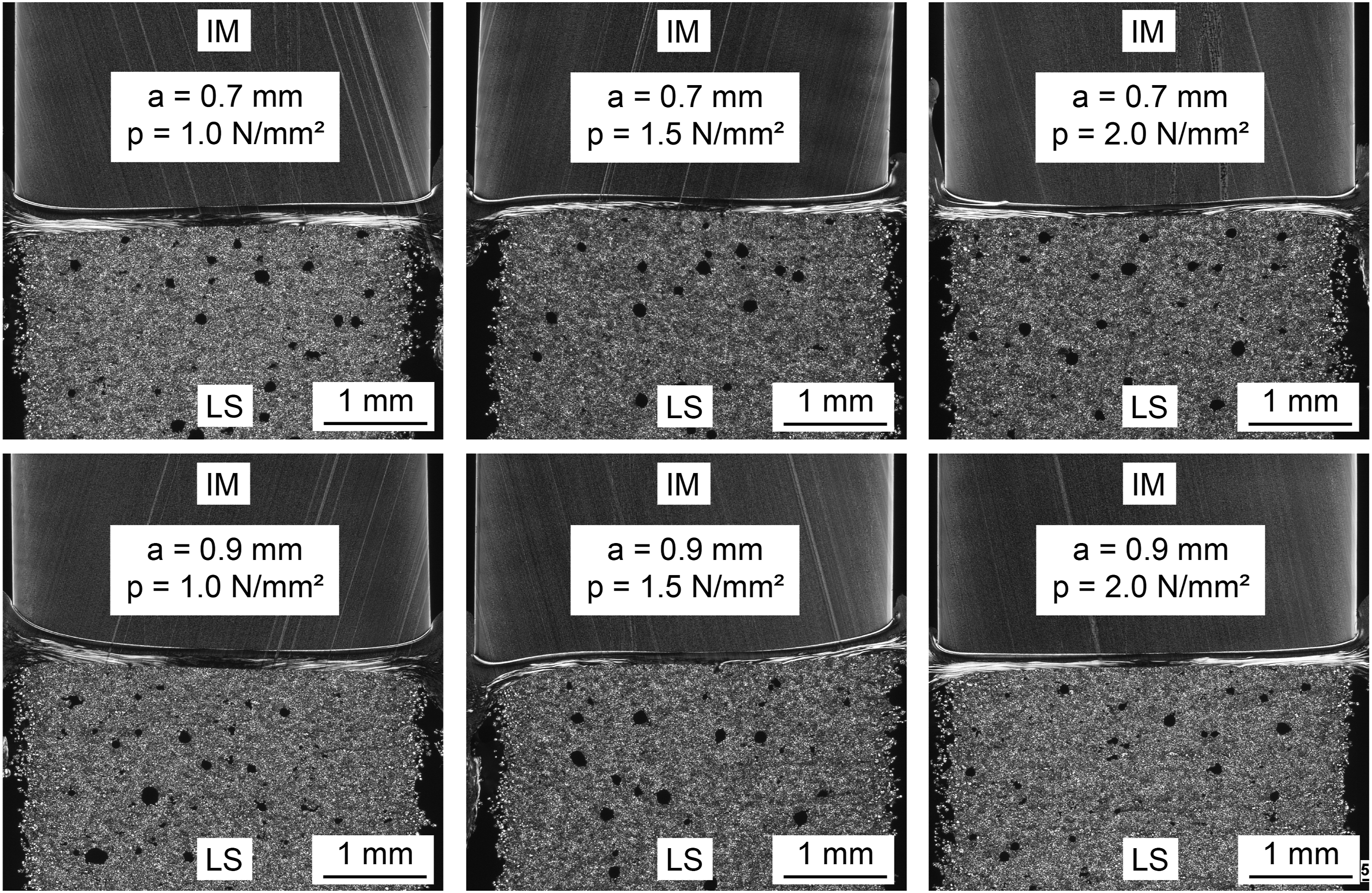

The weld bead resulting during vibration welding is shown in Figure 7(a). It can be seen that clearly more IM melt is displaced from the joining zone into the bead. In addition, the highly oriented areas occurring in the LS melt are also present in the bead area. Due to the almost equal residual melt layer thickness on both component sides, it is assumed that less melt is generated for the LS part during the vibration welding process. This hypothesis is in agreement with the determined characteristics of the joining partners. The increased degree of crystallization results in reduced damping properties for the LS component. In addition, the elastic ratio in the melt is increased. This leads to a reduced amount of energy dissiping into heat during welding. In combination with the shifted melting range to higher temperatures and thus a later melting compared to the IM, this supports the assumed reduced melt generation on the LS side.
The characteristics of the seam area can be seen for the middle of the seam in Figure 7(b) and the outer seam area in Figure 7(c). The typical morphological structure, consisting of deformed spherulites in the transition area to the base material and a recrystallized zone, is visible for the IM side. In contrast, the LS side consists of only one area. In the seam middle, Figure 7(b), a structure without superstructures is visible, which shows slight flow lines in the direction of the squeeze flow. This orientation becomes more pronounced with increasing distance from the seam middle. In the outer seam region, due to the increasing flow speed in direction to the weld bead, 31 a highly oriented microstructure is almost exclusively visible on the LS side, Figure 7(c). The flow lines begin in the transition area to the base material and continue over a wide area of the seam. Analysis of the highly oriented region shows transcrystalline structures in Figure 7(d), which are formed perpendicular to the orientation of the molecular chains. Starting point for such a crystalline growth in the weld zone is, in combination with a high chain orientation, a high nucleation density. 32 This is given on the LS component side by the flow aids contained in the LS powder. The high orientation on the LS side can be explained by the increased viscosity and thus reduced flow properties, in combination with the long molecular chains of the LS material. This leads to a strong elongation flow of the melt in the seam area, which results in a highly oriented microstructure.
Bond strength
Figure 8 shows the average stress–displacement curves of the short-time tensile tests for all process variants investigated. The tensile test curves were analyzed up to a fracture or the onset of necking. High reproducibility of the weld quality within each parameter variant can be seen due to the low standard deviation of the curves averaged from nine tests. In addition, the course of the average curves is almost identical for all parameter variations. This indicates a robust process over a wide parameter range. For further characterization of the bond quality, the maximum bond strength as well as the weld factor was evaluated, Table 1. For all parameter variants, a high bond strength in the range of the strength of the joining partners used is achieved. As a tendency, lower joining pressures lead to marginally higher achievable strengths. Considering the failure behavior, this effect is more obvious. While at a weld pressure of 1.0 N/mm2 all specimens fail outside the weld in the base material (mostly by necking in the IM component), for a pressure of 2.0 N/mm2 failure occurs for all butt joints by fracture in the weld seam. For 1.5 N/mm2, both failure mechanisms occur, fracture in the weld seam as well as fracture in the base material. The amplitude has no visible influence on the resulting bond quality. Average strength-displacement curves for vibration-welded LS-IM joints: (a) amplitude of 0.7 mm and (b) amplitude of 0.9 mm. Mechanical bond quality of vibration-welded LS-IM joint. Strength of joining partners: IM = 44.8 ± 0.1, LS = 49.6 ± 0.2.

The tensile tests show, that a high bond quality is achieved despite the clearly different seam structure on both sides of the joining plane. Furthermore, the process parameters in the vibration welding process can be varied over a wide range without noticeable reduction in strength.
Conclusion
The investigations show that joints of high strength can be produced by vibration welding between LS and IM components. The material and process induced differences between the LS and IM parts have a direct effect on the resulting weld seam formation. The increased spherulite size and higher crystallinity of the LS components leads to a higher stiffness and lower damping behavior during the frictional movement in the vibration welding process. Combined with the reduced flowability of the LS melt (compared to IM) as well as the lower melt rate due to an increased elastic ratio in the melt, less melt is generated on the LS side during the welding process. This leads to an inhomogeneous weld bead formation. Moreover, the different morphological characteristics of the weld seam as a function of the joining partner are striking. While the typical weld structure results for the IM side, the LS side consists exclusively of a highly oriented structure that exhibits transcrystalline structures. This can be attributed, among other things, to an increased elongation flow due to the reduced flowability in combination with longer molecular chains of the LS melt.
Contrary to other welding processes, such as infrared welding, 10 the welding parameters can be varied over a wide range without any loss of strength. Welding factors of approximately 1.0 are achieved for all parameter variants examined. Considering the fracture behavior, it can be seen that lower weld pressures are advantageous for the bond quality. The high process stability and reproducibility combined with the full utilization mechanical properties of the base material allow the vibration welding process to be used in industrial applications for LS-IM joints. The joining process may thus be applied to increase the functionality of small part quantities as well as for customer-specific individualization of series products.
As in the vibration welding process only one of the joining partners is vibrating actively and the second partner is passively forced to vibrate by the first partner, the clamping position may influence the welding process due to the different part properties of the joining partners (reduced damping, increased stiffness and reduced flowability of the LS parts). This influence will be investigated in further studies.
Footnotes
Acknowledgements
The authors thank the companies’ bielomatik GmbH (Neuffen, Germany), BMW AG (Munich, Germany), and Sintermask GmbH (Lupburg, Germany). Further, the authors thank the Evonik Industries AG (Essen, Germany) for providing the injection molding material. Further, we acknowledge financial support by Deutsche Forschungsgemeinschaft and Friedrich-Alexander-Universität Erlangen-Nürnberg within the funding programme “Open Access Publication Funding”.
Declaration of conflicting interests
The author(s) declared no potential conflicts of interest with respect to the research, authorship, and/or publication of this article.
Funding
The author(s) disclosed receipt of the following financial support for the research, authorship, and/or publication of this article: This work was supported by the Bayerische Forschungsstiftung (BFS) within the project FAB-Weld (AZ-1352-18).