
Abstract
Aqueous graphene oxide (GO) dispersion was used to produce fibers by wet spinning technique. In situ growth of carbon nanotubes (CNTs) in the graphene fibers was realized by chemical vapor deposition (CVD) of the obtained graphene oxide GO fibers with a diameter about 30 μm using acetylene as precursor gas. Carbon nanotubes with diameters of 107 and 407 nm were found in the resulted graphene fiber (GF) with creation of active nucleation sites as reduction oxygen containing groups in the GO sheets during the CVD process. XPS and Raman spectroscopy results combined with SEM image confirmed the conversion of the GO fibers to the CNTs/GF.
Introduction
Recently, the assembly of graphene nanosheets into continuous graphene fiber (GF) was easily achieved by wet spinning of graphene oxide (GO) liquid crystal phases.1–3 Due to defects, interfacial interaction between graphene sheets and alignment along a fiber axis direction, the strength, electron, and electrical properties of as-obtained fibers was rather low than what was expected. 4
Efforts had been made to improve mechanical, electronic, and electrical properties of GF. Combination of CNTs and graphene to form CNTs/graphene hybrid or composite fibers leads to the increased electrochemically active surface area and fast electron/ion transfer as the hybrid or composite structure combines the properties of two highly conductive carbon nanomaterials with a synergistic effect. 5 In situ growth technology, that is, chemical vapor deposition (CVD), is regarded as a promising way for fabricating large area, uniform, and high-quality CNTs/graphene hybrids because of its reasonable cost, high controllability, reproducibility, and scalability. Jiang et al. 6 obtained graphene oxide on CNTs surfaces by partially stripping CNTs in situ. The CNTs/RGO hybrid showed a high-specific surface area (581.4 m2 g−1) and specific capacitance (128 F g−1) due to solid connection between CNT and graphene sheets. Mahssa et al. firstly reported synthesis of graphene and carbon nanotube by filament chemical vapor deposition (CVD). 7 Combination of carbon nano tube (CNT) to graphene showed great improvement in mechanical and electron properties.8–12 Carbon nanotubes anchored on graphene substrates were prepared using microwave technique.8,9 By simple one-step chemical vapor deposition (CVD) using ethanol as precursor, Dong 10 synthesized a graphene–CNT hybrid material with bamboo like multiwall structure, which exhibited p-type field-effect characteristics and a significantly higher conductivity. The graphene–CNT hybrid has also been obtained using a solid-phase layer-stacking approach with ethanol wetting. 11 Graphene oxide (GO) was infiltrated into the CNT fibers to interlock CNT bundles. GO infiltrated CNT fibers exhibited improvement of 56% in ultimate tensile strength. 13
Few research studies have been published concerning preparation of CNTs/graphene composite fibers by CVD without adding any catalyst. In this research, GO fibers were prepared by wet spinning, and CNTs were incorporated to the fibers by thermal CVD to form CNTs/graphene composite fibers. With the combination of graphene and CNT, the composite fibers were expected to exhibit excellent mechanical and electrical properties.
Experimental
Materials
GO aqueous dispersion (10 mg/mL) was purchased from GaoxiTech. The metal ion content of the GO dispersion is less than 100ppm. GO dispersion was loaded into a 10 mL syringe and injected through a 27 G needle at a speed of 1.8 m/min into a rotating anhydrous alcohol bath with the same speed. The fibers were kept in the alcohol bath for 30 min to solidify and dried up in a vacuum oven at 80°C for 24 h.
Sample preparation
Acetylene (C2H2) was used as precursor gas for the growth of CNTs. GO fibers were placed inside a quartz tube CVD reactor (50 mm in diameter and 1000 mm in length) and heating process was carried out at a heating rate of 10°C/min under the presence of Ar at a constant flow rate of 400 sccm. As the temperature inside the reactor reaches 200°C, flows of H2 and C2H2 were added to the reactor at a constant flow rate of 100 sccm for each. H2 and C2H2 were stopped after the temperature inside the reactor reaches 750°C, and Ar was continued to cool down the reactor until it reached the room temperature. The schematic chart for preparing CNTs/GF is shown in Figure 1. Schematic chart of preparing CNTs/GF.
Characterizations
The morphology of the as received GO was observed using high-resolution transmission electron microscopy (HRTEM: Jeol ARM-1250) with an acceleration voltage of 100 kV. A field emission scanning electron microscopy (FESEM, Hitachi, S-4700) was used to characterize the CNTs in the graphene fibers.
Raman spectroscopy was carried out using a Renishaw RM2000 Raman spectrometer (Renishaw Plc, UK) attached to an Olympus optical microscope, and a He–Ne laser with wavelength of 514.5 nm. X-ray photoelectron spectroscopy (XPS) measurements were performed using an ESCALAB 250 spectrometer (Thermo Fisher Scientific, USA) using monochromated Al K at 200 eV for survey and 30 eV for high-resolution scans. Thermogravimetric (TG) tests were performed in nitrogen from 100 to 800°C at a heating rate of 10°C/min using a TGA Q600 (TA Instruments, U.S.A.).
Results and discussion
GO with large sheet size was reported to form fibers with good mechanical and electrical properties.14–16 For this reason, aqueous GO dispersion with sheet size larger than 10 μm was used to prepare GO fibers using wet spinning technique. TEM image confirmed the large size of GO sheets (Figure 2). Raman spectroscopy was applied to study the carbon structure of GO. Three peaks, that is, the G band (1587 cm−1) originated from the sp2-hybridized carbon atoms, the D band (1353 cm−1) caused by the defects involved in the sp3-hybridized carbon bonds, and the 2D band (2828 cm−1) represented the stacking of graphene sheets, were observable in the spectrum. The overlapped D band and G band indicated low graphitization degree of the GO due to large quantities of oxygen containing groups.
17
The relative low value of 2D/G, which is 0.18 in this study, exclaimed that the GO consists triple-layer and multi-layer graphene sheets. TEM image and Raman spectrum of GO as received.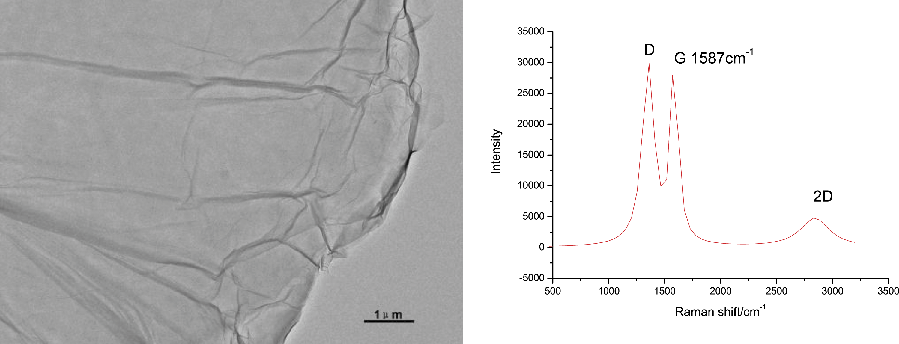
Continuous GO fibers (Figure 3(a)) with diameter around 30 μm were obtained by wet spinning technique using anhydrous alcohol as coagulation bath to solidify GO dispersion to fibers. Rough surface morphology with GO sheets stacked together was observed in the SEM image of the GO fibers, which was quite similar to the GO fibers reported by Xu.
18
SEM-EDS revealed that the fiber mainly consisted C and O, with no obvious metal ion being detected (Figure 3(a)). The GO fibers were placed into a thermal CVD reactor for in situ growth of CNTs in the fibers using C2H2 as precursor. As shown in Figures 3(b) and (c), numerous CNTs were grown in the surface of the fiber. As no metal ion was detected by SEM-EDS in the GO fiber, the growth of the CNTs was probably attributed to the catalytic actions of GO. The uniform hexagonal structure of GO contains epoxy and hydroxyl groups, create well-suited activated nucleation site which act as a root for growth of CNTs.
19
The Raman spectra of GO fiber and CNTs/GF (Figure 3(d)) confirmed the large conversion of GO to the graphene in the fibers. For GO fibers, the Raman spectrum exhibited two peaks with approximately equal height at 1357 and 1583 cm−1, which was attributed to D band and G band, respectively. In the spectrum of the fiber after thermal CVD, the D band became much lower with respect to the G band. The D band is associated with defects of the sample, and the G band corresponds to the graphitic band that is related to the ordering of the sample.
20
The ratio of the intensity of G band to the D band (G value) is an indicator of the graphitization degree of the carbon structure. The G value increased from 1.16 for the GO fiber to 6.25 for CNTs/GF, indicating GO largely transformed to graphene. SEM images of GO fiber(a), CNTs/GF (b, c), and Raman spectra (d).
Interestingly, two sets of CNTs with diameters of about 107 and 417 nm were grown in the fiber (Figure 3(c)). The reduction of oxygen containing groups in the GO produced activated nucleation site which act as roots for growth of CNTs as the atomic ratio of C/O increased from 2.36 for the GO fiber to 11.64 for CNTs/GF. To further investigate the change in functional groups of GO fiber during thermal CVD, high-resolution scans were performed to obtain the C1s spectra of the samples (Figure 4). To deconvolute the XPS peaks, the position and width of each Gaussian peak are set as the initial parameters and the intensity/peak area was obtained through optimization.
20
The binding energy of the C=C and C–C is at about 284.5 eV. The binding energy of the about 287, 288, and 289 eV is typically attributed to the C–O, C=O and O=C–O functional groups, respectively.
20
The percentage of C–O, C=O, and O=C–O groups was 28.89%, 14.05%, and 11.85% for GO fibers. After thermal CVD, no C–O and O=C–O groups were found in the CNTs/GF with only about 10.04% of C=O. These results are in good accordance with previous research.21,22 Functional groups of GO fiber and CNTs/GF obtained by XPS spectra.
The growth of CNTs in the GF may be attributed to the removal of C-O and O-C=O groups in GO fibers during thermal CVD. With increasing of temperature at inert atmosphere, GO was reduced to graphene by removing oxygen containing groups. From the TG and DTG curves of GO fibers (Figure 5), two weight loss peaks at 213.4 and 351.0°C, which corresponded to the reduction of C-O and O-C=O, were found with weight loss of about 37% and 19%, respectively. With the reduction of oxygen containing groups in the GO sheets, active sites for growth of CNT were produced. As there were two kind of active sites produced during CVD process, two set of CNTs with different diameters were in situ grown in the GF. No weight loss was found for the CNTs/GF up to 650°C, then gradual weight loss was found due to decomposition of residual oxygen containing groups in the thermal reduced graphene. For GO fibers pretreated at 650°C in inert atmosphere for 30 min, no CNT was found in the surface of the fiber after CVD process. This confirmed the proposed mechanism for growth of CNT during CVD in this study, as there was no C-O and O-C=O group in the pretreated fibers, and lack of active sites resulted no CNT was grown in the fiber during CVD. TG and DTG curves of GO fiber and CNTs/GF.
Summary
GO fibers with a diameter of about 30 μm were obtained by wet spinning technique using aqueous GO dispersion. By thermal CVD of the GO fibers, CNTs/GF composite fibers were obtained without adding catalyst. Two set of CNTs with diameter of 107 and 407 nm were found in the GF. Increase of G value from 1.16 for GO fibers to 6.25 for CNTs/GF indicated the reduction of GO to graphene. A mechanism for in situ growth of CNTs relating removal of oxygen containing groups in GO during CVD was proposed. Reduction of oxygen containing groups in the GO sheets resulted in increase of atomic ratio of C/O from 2.36 for GO fibers to 11.64 for CNTs/GF. Removal of C-O and O-C=O groups in the GO sheets during CVD process was supposed to create active sites for growth of CNT in different diameter.
Footnotes
Declaration of conflicting interests
The author(s) declared no potential conflicts of interest with respect to the research, authorship, and/or publication of this article.
Funding
The author(s) received no financial support for the research, authorship, and/or publication of this article.