
Abstract
Resistance element welding (REW) with a concealed rivet cover (Q235) was used to join steel-DP780 and Al-5052. The macroscopic morphology and the microstructure were observed using optical microscopy and scanning electron microscopy. The mechanical properties of the joint were also tested. The results show that the intermetallic compound (IMC) formed at the Q235/Al interface is FeAl3, while the IMCs formed at the DP780/Al interface are Fe2Al5 and FeAl3. The welding current has a significant influence on the nugget size, peak load, average hardness of aluminum heat-affected zone, and the bearing area of the aluminum plate. There are three fracture models of the countersunk rivet REW joint under a tensile-shear force: the interface failure fracture model, the fusion pullout failure fracture model, and the heat-affected zone failure fracture model. At a welding current of 18 kA, the nugget pullout failure mode is observed, and the best mechanical properties of the joint are obtained. The shear resistance of the joint can reach up to 5712 N.
Introduction
Introducing aluminum into a steel body is an important measure to produce lightweight cars. 1 Resistance spot welding (RSW), a fusion welding process, is widely used in the production of automobile body welding assembly and auto parts because it is fast, efficient, inexpensive, and easily mechanized and automated, along with yielding good welding surface quality.2–5 Although RSW plays a vital role in the quality of automotive manufacturing,6–9 its application in joining aluminum alloys and steel is challenging and presents two difficulties10-15: (1) The widely varying thermophysical properties of aluminum alloy and steel, such as melting point, thermal conductivity, and coefficient of linear expansion, are a source of significant stress on the joints after welding, increasing their susceptibility to cracking. (2) Under the influence of heat due to electric resistance, the aluminum alloy and steel form a series of intermetallic compounds (IMCs) at the spot-welding interface, rendering the latter extremely brittle and weak. In contrast, the resistance element welding (REW) process, which converts the main bearing part of the joint into a connection of the same material, effectively avoids the problem of hard and brittle phases prone to direct RSW of dissimilar metals. As a result, the bearing area becomes a nugget formed by the steel rivet and the steel plate, thereby improving the mechanical properties of the joint. This renders the REW process a suitable method for dissimilar metal connection for lightweight materials.
Volkswagen was the first to invent the REW technology that enabled the connection of advanced high-strength steel with lightweight materials. 16 A modified REW technology was proposed by Meschut et al.17–19 to join aluminum alloys and steel, where a through hole is punched in the upper aluminum plate, a steel rivet is inserted into the through hole, and the rivet and a lower steel plate are connected by RSW. As a result, a strong connection is formed between the aluminum alloy and steel. This method converts the dissimilar material connection into the same material connection, thereby avoiding the various problems associated with connection of dissimilar materials. Moreover, the REW process can be realized using the RSW equipment, thus significantly reducing the cost of the production process.
Meschut et al. 17 successfully connected cold-rolled automotive steel sheets to aluminum alloys, boron steel to aluminum alloys, and cold-rolled automotive steel sheets to carbon fiber-reinforced polymers using REW. They 18 combined REW with adhesive bonding and connected the 6061 aluminum alloy with 22MnB5. Because the bonding area was sufficiently large, the joint obtained by the hybrid joining process exhibited better tensile-shear mechanical properties. An attempt by Qiu et al. 20 to join 6061 aluminum alloy to mild steel via REW revealed FeAl IMC layers at the interface between the rivet and aluminum and FeAl3 IMC layers at the contact interface between the steel plate and aluminum. Holtschke et al. 21 joined the thermally sensitive sandwich material with the high-strength steel through a short welding time REW process. A comparison of the tensile-shear strengths of the aluminum alloy/boron steel joints generated by REW and RSW 22 showed that the tensile-shear strength of the joint obtained by REW can reach 7086.9 N, which is seven times the strength of the RSW joint. Similarly, Ling et al. 23 found that the fatigue strength of aluminum alloy/steel joints produced by REW was higher than that of the Al/Al RSW joints and the majority of the Al/steel joints. Furthermore, Manladan et al. 24 showed the applicability of the REW technique to connect magnesium alloy with stainless steel. An investigation of REW with upset steel rivet in aluminum alloy sheets of different thicknesses reported that as the thickness increased to 1.1 mm, the tensile-shear strength increased to 4500 N. 25
In this study, we have used countersunk holes and steel rivets to join the dissimilar metals 5052 aluminum alloy and DP780 dual-phase steel, which are used in the automotive industry for lightweight materials. It is also important to note that this process differs from other REW processes. This study explores a method used for countersunk head rivet REW to achieve the reliable connection of dissimilar metals of aluminum and steel. The REW process used in this study is shown in Figure 1. The concealment of the rivet cover caused the surface of the workpiece to become flat and smooth, rendering it resistant to injury or damage due to collision. After welding, the nugget diameter, rivet upset, indentation depth, and weld hardness were measured. Thereafter, the tensile-shear tests were conducted, and the fracture characteristics of the welded joint were investigated to determine the relationship between the welding parameters and mechanical performances of the REW joint. The resistance element welding (REW) process with concealed rivet cover.
Materials and Methods
Chemical composition of the experimental materials (wt.%).

The aluminum and steel samples were machined to 25 mm ⅹ 100 mm with a lap length of 25 mm (Figure 2), according to the method described in the American Welding Society (AWS) D17.2/D17.2M: 2013.
26
The countersunk hole was pre-fabricated in the center of the lap joint area of the aluminum alloy plate, followed by inserting the rivet unit into the countersunk hole such that the lower end surface of the rivet was level with the upper end surface of the aluminum alloy plate. Prior to the welding test, the aluminum alloy, duplex steel, and Q235 rivet samples were all cleaned using acetone. Tensile-shear specimen for the resistance element welding process.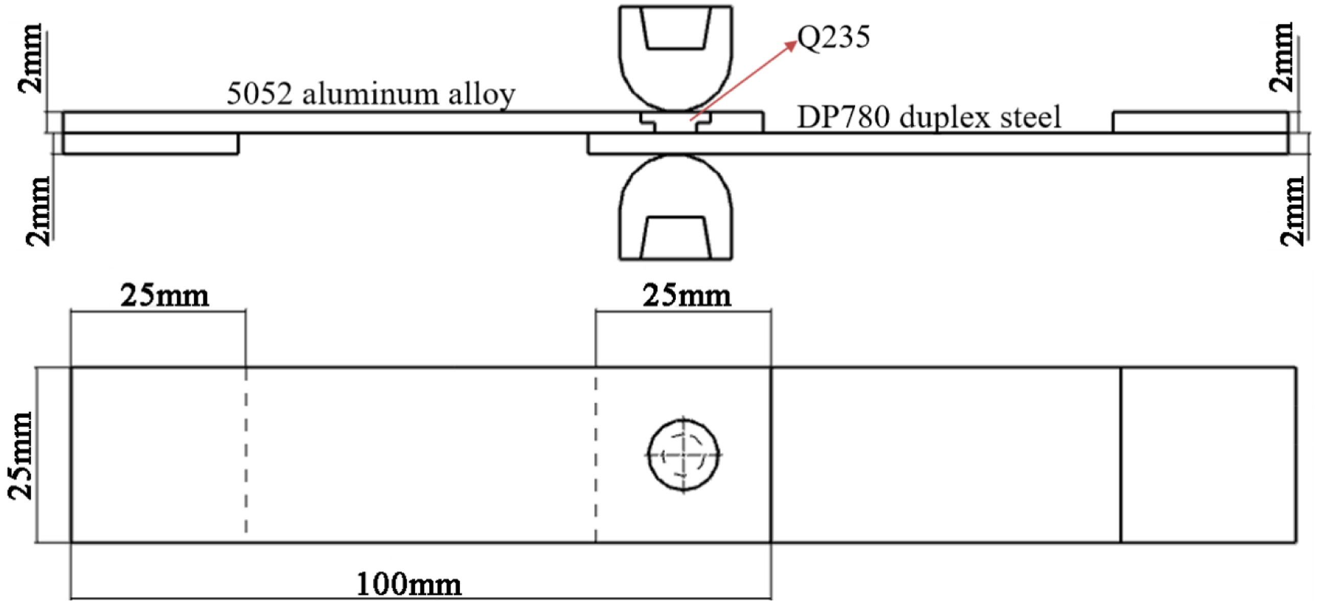
The welding test was conducted using the DTN-200 single-phase AC spot-welding machine. A spherical electrode with a diameter of 16 mm was selected; the electrode material comprised of chromium, zirconium, and copper. After the preliminary experiments, the welding time and the electrode pressure were fixed at 15 cycles and 0.3 MPa, respectively, and the welding current was increased from 12 to 22 kA while welding a joint every 2 kA. Five samples were spot welded under the same parameters, wherein two samples were used for macroscopic and microscopic inspection, while the other three were used for tensile-shear tests. The specimens for macroscopic and microscopic examination were cut along the center of the nugget, subjected to rough grinding, fine grinding, and polishing steps, and then etched with 4% HNO3 + 96% C2H5OH and 18% HF + 12% H3PO4 + 70% H2O, respectively. The macroscopic morphology of the joint was observed using a stereo microscope, while the microstructure was observed via a metallographic microscope. The microstructure characteristics and chemical compositions of Fe/Al reaction layers were investigated using scanning electron microscopy (SEM) equipped with energy dispersive spectroscopy (EDS). The hardness of the RSW joint was measured using a Vickers microhardness tester. The experimental force on the steel side and the aluminum alloy side was 100 and 25 g, respectively, and the holding time was 10 s. The longitudinal spacing of the measuring points was 0.1 mm, and the lateral spacing of the measuring points was 0.2 mm. The tensile-shear load was examined by a universal testing machine at a crosshead velocity of 1 mm/min.
Results and discussion
Macrostructures and microstructures
Figure 3 shows the cross section of a typical joint generated by REW at a current of 18 kA. Clearly, the nugget is offset to the side of the duplex steel. While the duplex steel has a small thermal conductivity and slow heat dissipation, the aluminum alloy possesses a large thermal conductivity and faster heat dissipation. The spot-welding temperature shifts to the side of the duplex steel, in turn offsetting the nugget to this side; a similar phenomenon was observed by Ling et al.
22
In addition, the indentation depth on the Q235 side is greater than that on the duplex steel side because the hardness of the latter is greater than the hardness of Q235. This also causes the duplex steel to bulge into the Q235 rivet, which, as reported by Chen et al.,
27
causes mechanical locking in lap shear loading. Moreover, the rivet was upset under the effect of the electrode force and heat input. The aluminum alloy near the rivet melts, and the partially melted aluminum alloy is extruded between the two plates, resulting in a reduced bearing area of the aluminum plate. Optical microscopy image of the resistance element welding joint.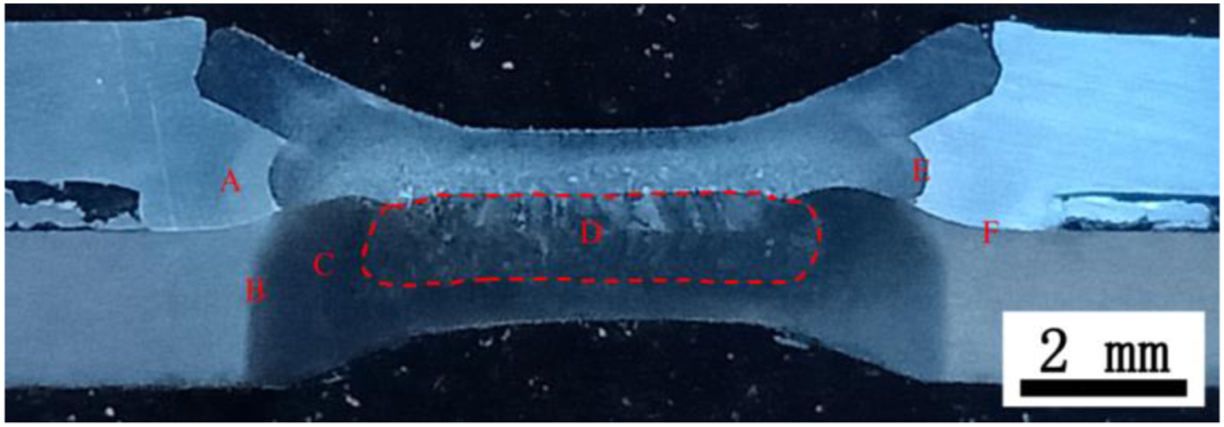
The microstructures of regions A–F denoted in Figure 3 are magnified in Figure 4. Region A is the transition zone of the Al alloy, which can be divided into a fusion zone (FZ) and a heat-affected zone (HAZ). The FZ consists entirely of uniformly distributed dendrites. Region B is the intercritical HAZ (ICHAZ) of DP780, where the peak temperature ranges between Ac1 and Ac3.
28
The base metal (BM) of DP780 is transformed into ferrite and austenite during heating. Due to rapid cooling, the austenite can be completely transformed into martensite; thus, the microstructure of ICHAZ of DP780 is observed as a two-phase structure including ferrite and martensite. As reported by Ma et al.,
29
the martensite content increases closer to the nugget with increasing peak temperature. Region C is the upper critical HAZ (UCHAZ) of DP780, which experiences a peak temperature between Ac3 and Tm.
28
The UCHAZ can be further divided into two parts, that is, coarse grained HAZ (CGHAZ) and fine grained HAZ (FGHAZ). The CGHAZ is closer to the nugget, and the austenite grains rapidly grow due to higher peak temperature, promoting the formation of the coarse martensite structure. The FGHAZ experiences a lower peak temperature; thus, the austenite grains are not completely grown, forming a fine martensite structure after cooling. Region D is the nugget of the REW joint, which is primarily composed of lath martensite owing to the fast cooling rate of the RSW process. Microstructures of the resistance element welding joint in Figure 3. (a) Region A; (b) Region B; (c) Region C; (d) Region D; (e) Region E; and (f) Region F.
Energy dispersive spectroscopy point scan of the intermetallic compound layers in Figure 4(e) and (f).

Although the IMC exhibits brittle properties, a thin layer of IMC with an appropriate thickness can significantly increase the joint strength. According to theories of contact mechanics, a stress singularity exists at the dissimilar material interface, which initiates cracking under loading, thereby causing failures. Therefore, the presence of a high-strength intermetallic layer can alleviate this effect and enhance joint quality. 32 However, if the IMC layer is too thick, cracks are easily initiated and propagate through the hard IMC tangles. 33
Microhardness distribution
Figure 5 shows the microhardness profiles of the REW joint at a current of 18 kA. Based on the varying hardness value (HV) distributions, the hardness of the steel side is divided into five regions (Figure 5(a)): Region A is the BM of Q235 with an average hardness of 179 HV. Region B is the HAZ of Q235, where the hardness increases from 323 HV to 367 HV. This is because at higher temperatures, the austenite rapidly grows closer to the nugget, resulting in a coarsened superheated structure after cooling, which reduces toughness and increases hardness. Region C is the nugget with an average hardness of 462 HV. The hardness of the center is greater than the hardness of the edge. According to Svensson et al.,
34
the hardness of the full martensitic nugget is related to the cooling rate. When the cooling of the center mainly occurs through the water-cooled electrode in the axial direction, the cooling of the edge predominantly passes through the adjacent cold BM in the radial direction. Faster cooling in the center of the nugget results in higher hardness. Region D is the HAZ of DP780. The average hardness values of UCHAZ and ICHAZ are 483.4 HV and 409.5 HV, respectively. A softening spot occurs in the subcritical HAZ near the BM, and its hardness is only 90% of the BM. Hernandez et al.
35
stated that the heating temperature in this region is below AC1, resulting in non-isothermal tempering of martensite in the BM of DP780. The formation of non-isothermal tempered martensite reduces the hardness of the zone to 215 HV. Region E is the base metal of DP780 with an approximate hardness value of 230 HV. Microhardness characteristics of the resistance element welding on (a) the steel side and (b) the aluminum side.
The hardness of the aluminum side (Figure 5(b)) is divided into three regions: Region F is the fusion zone with an average hardness of 73 HV, which is lower than the hardness of the BM. This is because the base material of the nugget zone undergoes melting and crystallization; therefore, the aging strengthening effect in the original base material is eliminated and the hardness is decreased. Region G is the HAZ of 5052 with an average hardness of 72 HV. Zhang et al. 36 reported that the softening of the non-heat-treated reinforced aluminum alloy welded joints is mainly caused by the coarse grain in the HAZ and the disappearance of the local cold work hardening effect of the welded joint. Region H is the BM of 5052 with an approximate hardness of 78 HV.
Tensile-shear performance
For the REW joint, the welding current has significant effects on the nugget size, the peak load, the average hardness of aluminum HAZ, and the bearing area of the aluminum plate.
As the welding current increases from 12 to 22 kA, the nugget diameter increases from 3.7 to 8.2 mm, while the joint peak load increases from 3801 to 5712 N and then drops to 5440 N (Figure 6). Below 18 kA, the increase in the current results in a corresponding increase in the heat input. This causes the nugget size to increase, which in turn is followed by increases in volume of the molten metal and joint load capacity. Above 18 kA, on the one hand, the lower end surface of the rivet is upset; thus, the bearing area of the aluminum plate is reduced from 32.8 mm2 to 29.5 mm2, resulting in a decreased bearing capacity of the joint. On the other hand, the increase of the heat input reduces the hardness of the HAZ of aluminum to 72 HV. Under the action of the tensile-shearing load, it is expected that the aluminum HAZ would neck and fracture. Effect of welding current on the nugget diameter, peak load, average hardness of aluminum heat-affected zone (HAZ), and bearing area of the aluminum plate.
Failure modes
In the tensile-shear tests, three failure modes were observed: the interfacial failure mode (Figure 7(a)), the nugget pullout failure mode (Figure 7(b)), and the aluminum HAZ fracture mode (Figure 7(c)). When the welding current is below 14 kA, the failure mode is the interfacial failure mode. In this case, the nugget is too weak to withstand the tensile-shear load and the crack propagates through the fusion zone. When the welding current is between 14 and 18 kA, the nugget pullout failure mode appears and the nugget remains attached to the Q235 rivet. This is due to the high strength of the dual-phase steel, which makes plastic deformation difficult. Cracks are generated under tensile stress and propagate along the lowest hardness of the nugget edge until the nugget is pulled out. Above 18 kA, the failure mode is the aluminum HAZ fracture mode, which is caused by a significant decrease in the hardness of HAZ and the reduction of the bearing area of aluminum; the aluminum HAZ is more prone to necking followed by its fracture. Three typical Al/steel resistance element welding fracture surfaces from the tensile-shear test: (a) interfacial failure mode; (b) nugget pullout failure mode; and (c) Al heat-affected zone fracture mode.
Figure 8 shows the SEM micrographs of the fracture surfaces identified in Figure 7. The smooth facets at the fracture surface suggest brittle cleavage fracture (Figure 8 (i)), while the presence of most of the dimples and small smooth faces on the fracture surface indicate a mixed fracture (Figure 8 (ii)). However, only dimples with significant stretching were found in the fracture, which indicates a ductile fracture (Figure 8 (iii)). Scanning electron microscopy images of fracture surfaces as marked in Figure 7. (iv), (v), and (vi) are enlarged views of (i), (ii), and (iii), respectively.
Figure 9 depicts a typical load–displacement curve of the REW. For the tensile-shear curve of the interfacial failure mode, the nugget is very brittle and has lower peak load. For the tensile-shear curve of the nugget pullout mode, the nugget is pulled out of the steel plate during the drawing process, and the curve rapidly decreases to zero after the nugget breaks. For the tensile-shear curve of the aluminum HAZ fracture mode, the nugget on one side of the aluminum HAZ first necks and fractures in the direction of stretching, while on the other side, it remains connected and is slowly pulled off under the action of the tensile-shear load. Load–displacement curves for three typical failure modes: interfacial failure mode, nugget pullout failure mode, and aluminum heat-affected zone fracture mode.
Conclusions
From this study, the following conclusions can be drawn: 1. The REW process with countersunk rivets enables a reliable connection between the 2-mm thick materials of 5052 aluminum alloy and DP780 dual-phase steel. Under the optimized welding parameters of 18 kA, 15 cycles, and 0.3 MPa, the IMCs formed by the DP780/Al alloy are Fe2Al5 and FeAl3, and the IMC formed by the Q235 rivet/Al alloy is FeAl3. The peak load of the joint can reach 5712 N, and the failure mode appears as nugget fracture mode. 2. Below the welding current of 18 kA, the peak load of the joint increases with the nugget diameter. However, above 18 kA, the peak load of the joint decreases as the average hardness of the aluminum HAZ and the bearing area of the aluminum plate decrease. 3. At a welding current of 14 kA, the failure mode appears as the interfacial failure mode; between 14 and 18 kA, it appears as the nugget fracture mode; and above 18 kA, it appears as the aluminum HAZ fracture mode.
Footnotes
Declaration of conflicting interests
The author(s) declared no potential conflicts of interest with respect to the research, authorship, and/or publication of this article.
Funding
The author(s) disclosed receipt of the following financial support for the research, authorship, and/or publication of this article: This work was supported by the National Natural Science Foundation of China (51771071).