
Abstract
Marine engineering components, such as ship stern shafts, are often subject to local overload, wear and seawater erosion. In order to improve the performance and service life of marine engineering components, the CrFeCoNiNbx (x = 0, 0.25, 0.5, 0.75 and 1) high-entropy alloy (HEA) coating were prepared on the 42CrMo substrate by laser cladding. The microstructure, microhardness, wear behaviour and the corrosion resistance of the prepared HEA coatings with different Nb contents were evaluated. Results show that the cladding layer of CrFeCoNiNb0 is composed of single dendrites with a small amount of short rod-shaped protrusions distributed along the dendrites. The addition of Nb promotes growing of the original dendrite structures into interdendritic structures with internal substructures retained. Apart from the variations in the microstructure, the formation of the Laves phase, which is both hard and corrosion resistant, is also an important factor in the performance of the cladding. This variation leads to the increase of the microhardness of the cladding layer, accompanying with the improvement of wear resistance property. Notably, the improvement of microhardness is ascribed to the combined contribution from the refinement strengthening, the solid-solution strengthening and the dispersion strengthening by Laves phase. The improvement of the corrosion resistance is mainly attributed to dense passivation film formed by the Cr and Nb on the surface of the cladding layer. The above results suggest that the CrFeCoNiNbx cladding layer could achieve synergistic interaction between the mechanical properties and the corrosion resistance on stern shaft surface.
Introduction
The traditional alloying strategy is to add small amounts of minor elements to one or two major elements. However, this method of major elements severely limits the range of possible element combinations. The high-entropy alloy (HEA) is a type of multi-principal element alloy. HEAs have many advantages based on the high-entropy effect, the lattice distortion effect, the slow diffusion effect and the cocktail effect. The HEA has excellent properties such as high strength, high hardness, good ductility and wear resistance, excellent corrosion resistance and oxidation resistance, etc., and the HEA is expected to be widely used in the aerospace and marine engineering.1–3
As the key properties for practical applications, the mechanical properties and corrosion resistance of HEAs have always been the research focus. In order to enhance the FeCoNiCr HEA coating properties, it is effective to incorporate elements with special properties, such as Nb, Ti, Al, Cu. Several minor elements have been added to improve the mechanical properties and corrosion resistance of FeCoNiCr HEA.
In general, the addition of specific elements will inevitably lead to lattice distortion and phase composition transformation, which directly affects the mechanical properties of the alloy through the combination effect of the solid-solution strengthening, the secondary-phase hardening and the grain refinement.1–5 To improve the mechanical properties, the element Nb was added to the FeCoNiCr HEA coating by Chung et al. 1 The CoCrFeNiNb0.5 HEA was proved to have superior fracture toughness and strength at room temperature due to the hierarchical eutectic structure. 1 The AlCoCrFeNiTix with excellent mechanical properties at room temperature was prepared by Zhou et al. 2 Their results show that AlCoCrFeNiTi0.5 alloy has excellent comprehensive mechanical properties, which is attributed to the solution strengthening mechanism of Ti elements. Research result also shows that the AlxCoCrCuFeNi HEAs exhibit promising mechanical properties, including excellent high temperature strength and good wear resistance. 3 As an added element, the atomic radius of Nb element is much larger than that of FeCoNiCr, and the introduction of Nb element can change the crystal structure of the alloy for better performance through lattice distortions and solid-solution strengthening.
On the other hand, these minor elements play an important role in resisting corrosion by forming protective oxide films.6–9 The most common types of corrosion are uniform corrosion and local pitting. Pitting preferentially begins at surface inhomogeneities, and oxides formed at these sites or along their periphery generally have no protective effect. In addition, impurity phases, second phase precipitation and segregation are detrimental to the continuity of the passivation film. Therefore, one of the key factors in determining the pitting resistance is the ability to form a continuous passivation film without component defects over the entire surface. The corrosion properties of AlCoCrFeNi HEA coatings were investigated by Li et al. 6 It was found that the absence of Cr-rich intercellular segregation and nanoscale precipitates resulted in a relatively uniform corrosion attack. This differed from the severe galvanic corrosion attack. It was reported that the Al0.1CoCrFeNi HEA showed greatly longer incubation period and lower erosion corrosion rate compared with SS316L steel, which was attributed to the high work-hardening behaviour and stable passive film on the surface. 7 Shi et al. investigated the corrosion behaviour of AlxCoCrFeNi HEAs. They found that the increase in Al caused the passivation film to thicken/disperse, thereby reducing the local corrosion resistance. 8
Moreover, laser cladding, as a surface modification technology, has the characteristics of rapidly cooling and heating, which can promote the formation of simple solid solution. In addition, compared with other surface modification technologies, the thickness of the laser cladding layer is higher (≥0.8 mm). A good metallurgical bonding is formed between the cladding layer and the substrate, which has better performance than the alloy with mechanical bonding. With the further study of FeCoNiCr HEA, Nb is considered as an element to improve hardness and corrosion resistance. It is also an attractive research point to explore the synergistic mechanism of mechanical properties and corrosion resistance of CrFeCoNiNbx HEA cladding layers.
Materials and methods
Sample preparation
The 42CrMo with dimensions of 70 mm × 15 mm × 10 mm was employed as substrate, and the surface was polished, then cleaned with alcohol and air-dried. The powders were weighed according to the atomic ratio of CrFeCoNiNbx (x = 0, 0.25, 0.5, 0.75 and 1) and the composition of the HEA powder is shown in Table 1, with a purity of over 99% and a particle size of 200-400 mesh. The powder was uniformly coated on the surface of the substrate, and the thickness of the powder was about 1 mm. Then it was put into the drying container at 100 °C for 1.5 h. Last, laser cladding was performed in a single laser track with the scan speed of 3 mm·s−1, the output power of 1.4 kW and the spot diameter of 4 mm, which were optimised to obtain a smooth coating surface with a uniform microstructure and a good metallurgical bonding with the substrate. The prepared laser cladding sample is shown in Figure 1.
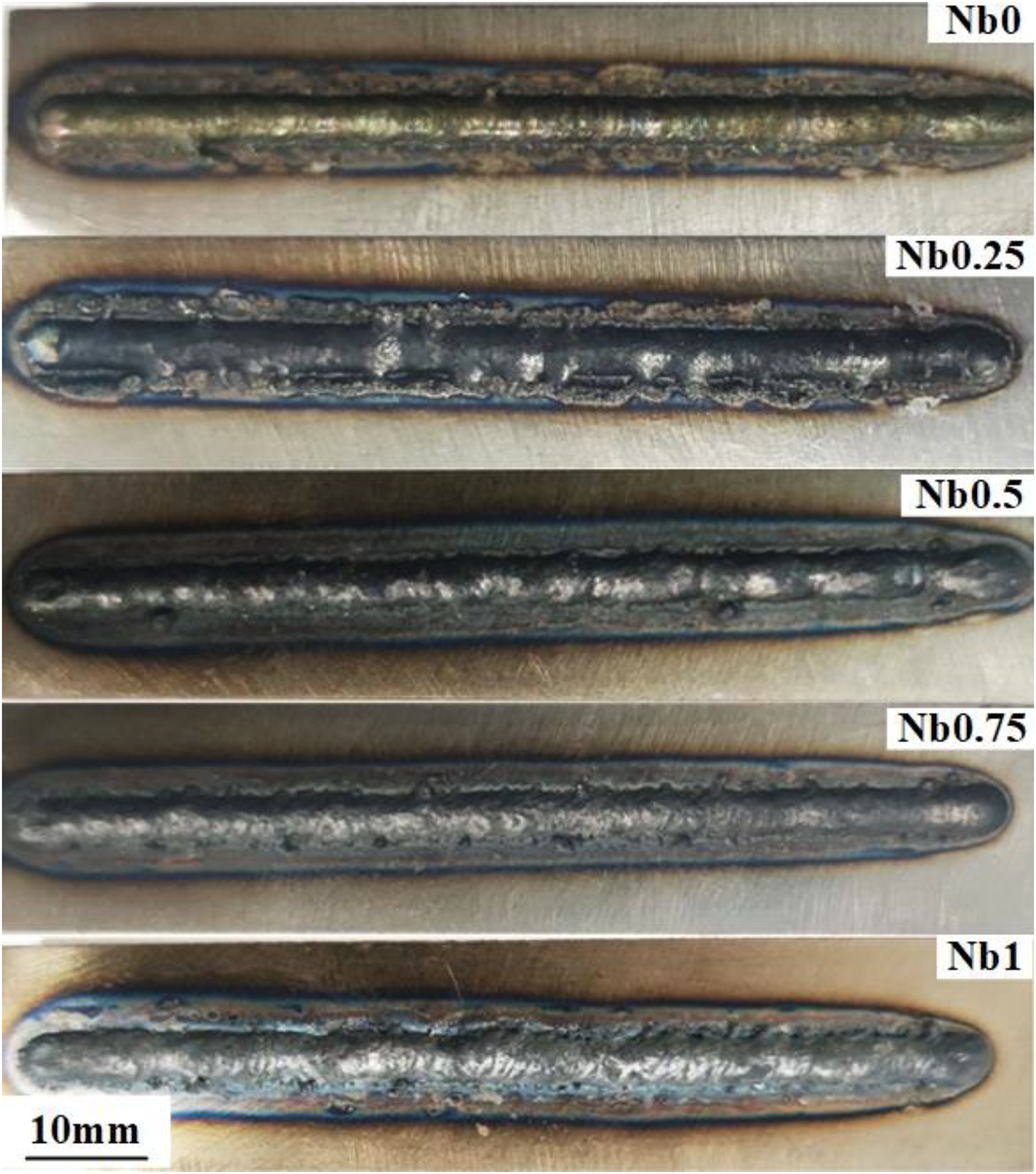
Coating morphology.
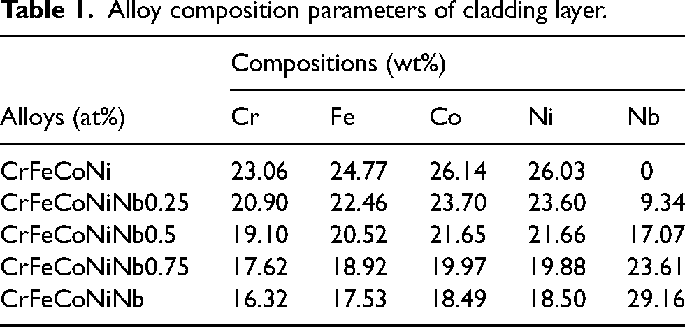
Alloy composition parameters of cladding layer.
Microstructure characterisation
The surface of the prepared sample was cut, ground and polished, and then the sample was corroded by aqua regia for 30s. Subsequently, the grain topography of the sample was examined by scanning electron microscopy (SEM) and energy dispersive spectroscopy (EDS). In addition, X-ray diffraction (XRD) was also performed for structural characterisation.
Performance test
The structure was characterised by Rigaku Ultima IV, and the copper (Cu) was selected as the target material for the experiment, and a voltage of 40 kV and current of 40 mA were applied for the study. The size of the sample was 15 mm wide and about 8 mm long. The Vickers hardness was measured using the HV-1000 Vickers microhardness tester with a load of 10 N for 10 s. Each reported microhardness value was measured from the top of the coating to the substrate with an interval of 0.2 mm. Each reported microhardness value was an average of three measurements. The wear test was evaluated by the UMT-3 TriboLab. The specific parameters were set as follows: the unidirectional displacement was 5 mm, the frequency is 2 Hz, the load was 10 N, and the test duration was 30 min. To ensure that all tests were performed under the same conditions, a 9.525 mm diameter Si3N4 ball was used in dry sliding conditions and a fresh Si3N4 ball was used. Each sample was measured three times as an average value to ensure data accuracy. After the wear test, the abrasion loss of the sample was carried out by laser scanning confocal microscope (LSCM), and the material loss of the wear area was calculated. The samples were sealed in epoxy resin with only one exposed surface area of 1 cm2 prior to electrochemical corrosion test. The potentiodynamic polarisation test was performed in a typical three-electrode cell. The cell consisted of the test sample as the working electrode, a saturated calomel reference electrode (SCE) and Pt as the counter-electrode. The measurements were performed in 3.5 wt% NaCl solution at 25°C under atmospheric pressure, using the CHI660E electrochemical workstation manufactured by Shanghai Huachen. The open circuit potential (OCP) was recorded for 30 min to obtain a stable potential before these tests. Then electrochemical impedance spectroscopy (EIS) data were acquired from 100 kHz to 10 mHz with potential amplification of 5 mV. Each sample was scanned from an initial potential of −1 V to a final potential of 1 V at a rate of 1 mV/s for potentiodynamic polarisation measurements. Electrochemical parameters were obtained using CH Instr. analyst software.
Results and discussion
Phase analysis
The XRD pattern of the CrFeCoNiNbx (x = 0, 0.25, 0.5, 0.75 and 1.0) cladding layers are shown in Figure 2(a). Two phases can be observed in the CrFeCoNiNbx high-entropy cladded layers, namely the FCC and the Laves phases. The CrFeCoNiNb0 and CrFeCoNiNb0.25 coatings contain a large amount of the FCC phase of Co(Ni, Cr)Fe, and the XRD pattern reveals distinct peaks, namely (1 1 0), (2 0 0), (2 2 0) and (3 1 1). When the value of x exceeds 0.25, new diffraction peak (1 1 2) appears attributed to the Laves phase. Apparently, as shown in Figure 2(b), with the increase of Nb content, the lattice constant of Laves phase increases and the lattice strain increases correspondingly. According to Figure 2(c), the peak (1 1 1) FCC tend to shift to the left with the increase of Nb. However, for x = 1 it tends to shift to the right, and this is due to that as Nb content increases, the microstructure of the cladding is more precipitated in the form of the Laves phase, resulting in the release of lattice distortion energy for the FCC solid solution. Despite having a large atomic radius, Nb has low solubility in the FCC and contributes to the formation of Nb-rich Laves phases, such as (Co, Cr, Fe, Ni)2Nb. It is worth noting that the Laves phase has a relatively high degree of embrittlement, and the increase of the Laves phase may lead to cold cracking. In addition, with the increase of Nb, the lattice constant calculated from the (1 1 1) FCC peak keeps increasing until x = 1 as shown in Figure 2(d). Correspondingly, the lattice strain in the FCC phase increases first and then decreases.
XRD patterns and lattice parameter of the CrFeCoNiNbx (x = 0, 0.25, 0.5, 0.75 and 1) cladding layers: (a) complete XRD pattern; (b) lattice constant of the Laves peak; (c) detailed scans for the peak (1 1 1) of the FCC solid-solution phase; (d) lattice constant of the (1 1 1) FCC peak.
Microstructure analysis
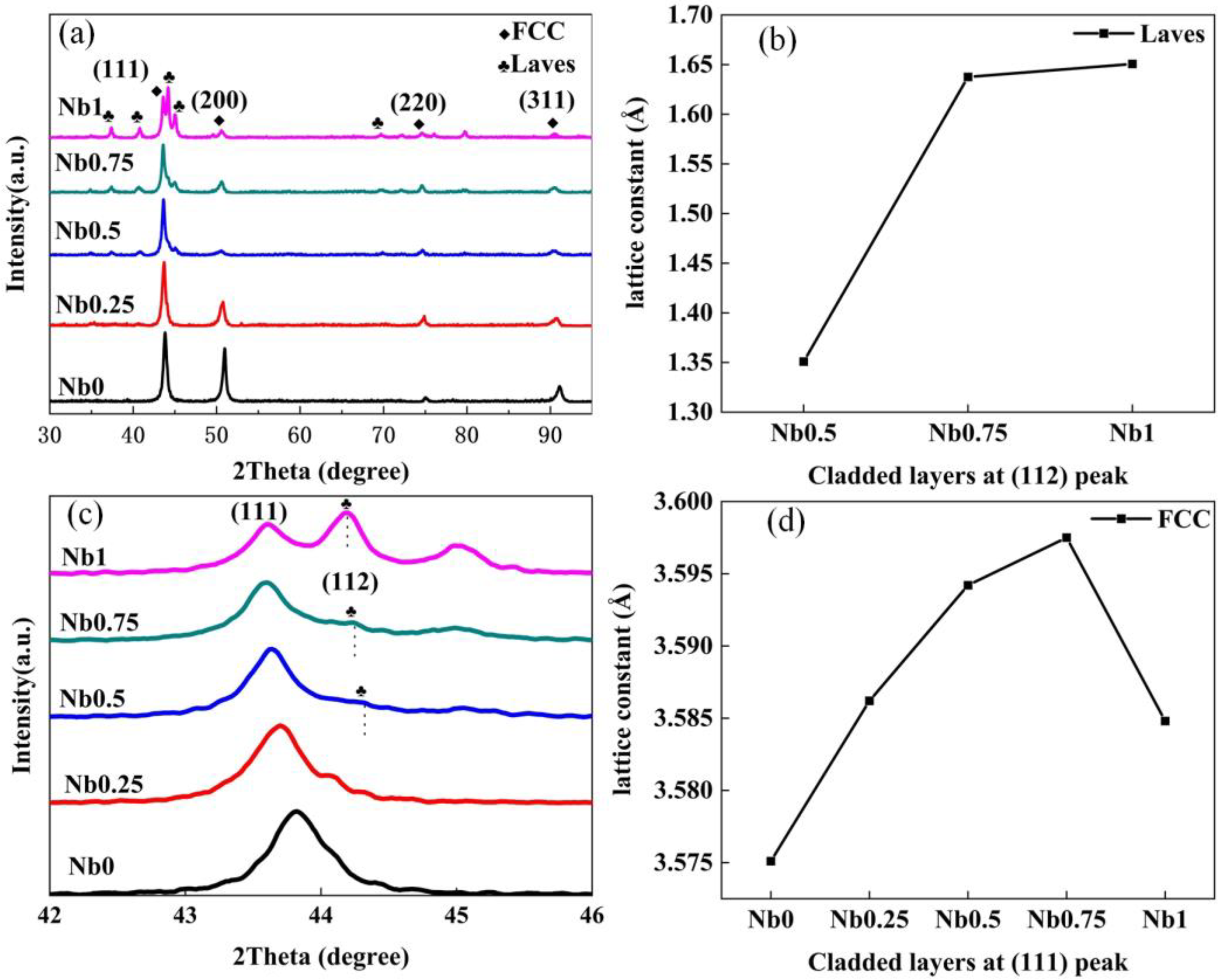
Significant microstructural evolution can be clearly observed in Figure 3 with the increasing of Nb content. The growth of the microstructure follows the principle of dendrite growth, and the cladding layer is generally composed of cellular grains. But there is a clear trend of grain refinement, which is a common feature of x values from 0 to 0.75. This can be attributed to a significant increase in the extent of lattice distortion. Since the lattice distortion energy is larger than the grain boundary energy, the normal diffusion of atoms is hindered and the grain growth is limited. Therefore, with the increase of x value, the cladding layer has a greater resistance to grain growth. It needs to be noted that A represents the bright region and B represents the dark region. According to Figure 3(b) and (c), the cladding layer of Nb0 mainly consists of the single dendrites. Some short rod-shaped protrusions (region A) are sporadically distributed along the dendrites, and no clear interface can be distinguished clearly. Region A is the Cr-rich precipitate, and Fe, Co, Ni, Cr are distributed in region B uniformly. As the value of x increases to 0.25, those protrusions in region A become relatively wide and smooth. Except Nb is almost concentrated at the grain boundaries, the other elements are uniformly distributed in region A and B, and the cladding is dominated by the FCC phase. With the further increase to 0.5, 0.75 and 1 in Nb, the typical lamellar eutectic structure, including the Laves phase revealed as the bright region and the FCC phase revealed as the dark region can be observed. Moreover, according to the XRD result, these protrusions in region A become larger and gradually transform into a new phase. From the observation of line scan results, the content of each element in region A is higher than that in region B. Combined with the analysis of EDS and XRD, region B is always FCC phase, and when x > 0.5, region A changes into (FCC + Laves) phase. Obviously, the addition of Nb promotes the growth of the original dendritic structures into interdendritic structures with retained internal substructures.
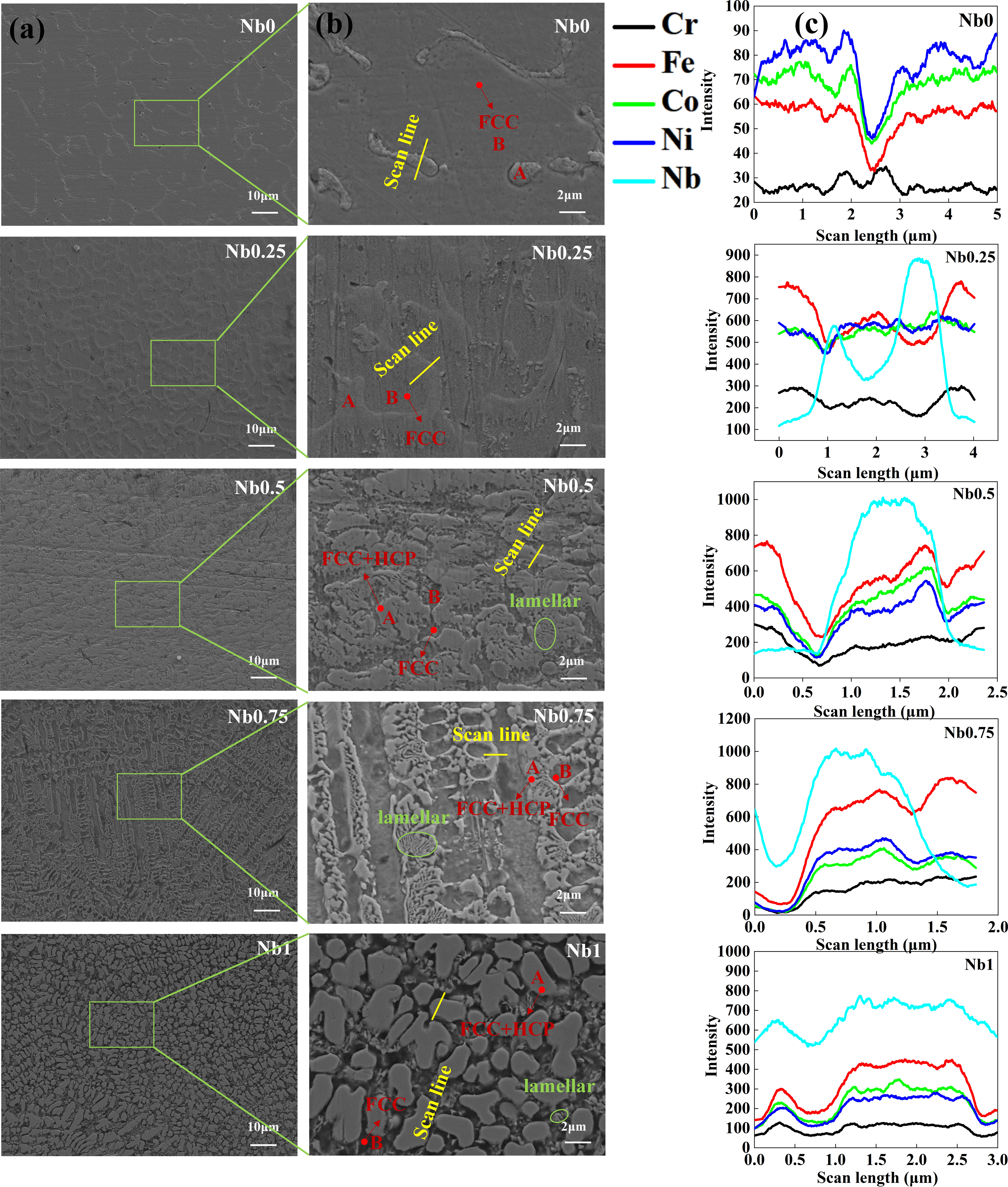
SEM and EDS images of CrFeCoNiNbx (x = 0, 0.25, 0.5, 0.75 and 1) cladding layers: (a) SEM of cladding layers, (b) magnification of the framed portion in (a) and (c) EDS of scan line.
Vickers hardness
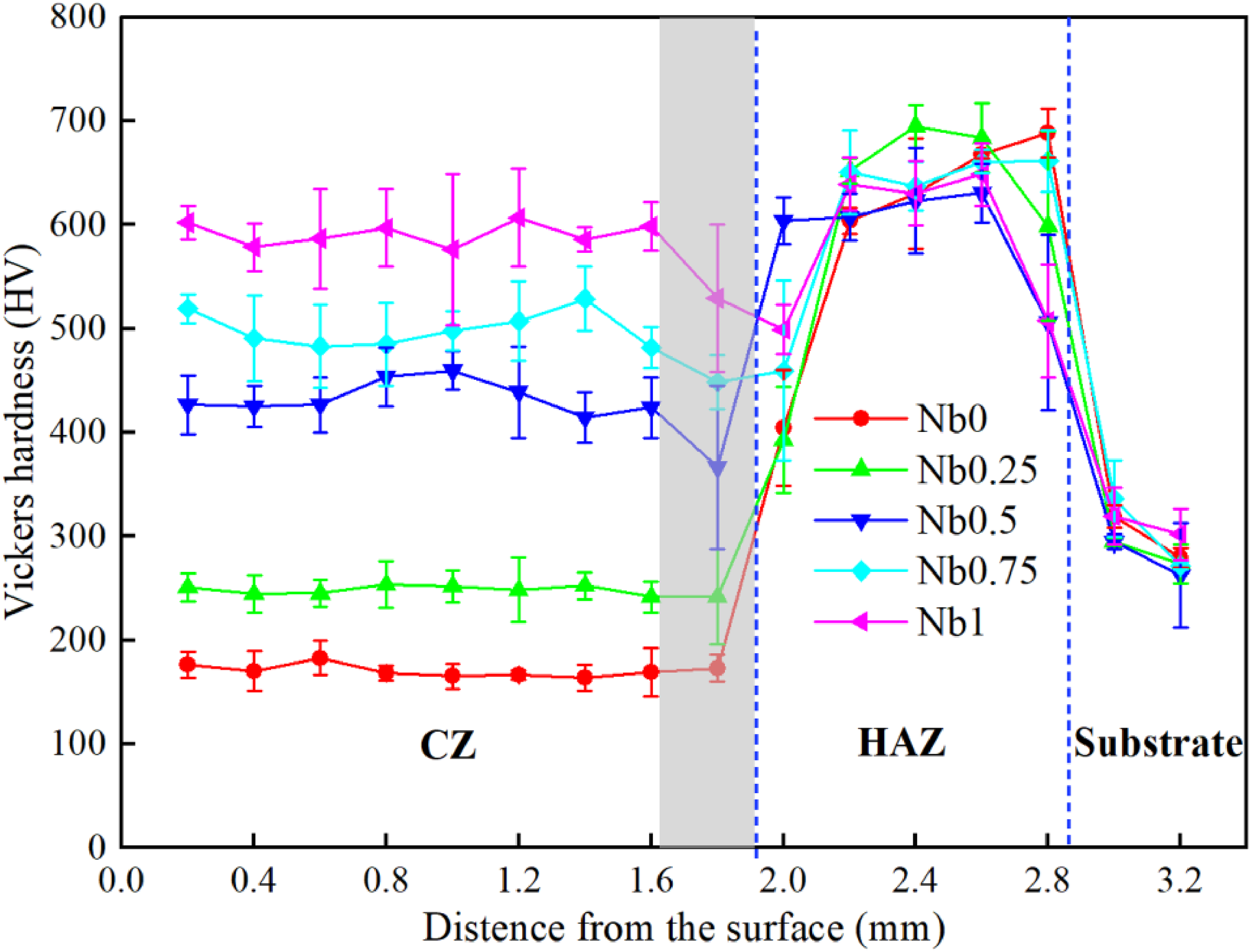
The Vickers hardness values for CrFeCoNiNbx (x = 0, 0.25, 0.5, 0.75 and 1) cladding layers are displayed in Figure 4, which was tested from the top of the CZ to the substrate. It is found that the microhardness of CrFeCoNiNbx cladding increased with the increase of Nb content. The improvement in microhardness of the cladding can be attributed to fine grain strengthening, solid-solution strengthening and increasing the proportion of Laves hard phase. The cladding layer of CrFeCoNiNb0 has a coarse grain and is composed of FCC soft phases, resulting in low hardness. As the value of x increases, the Hall-Petch effect occurs, which leads to grain refinement and helps increase hardness. As the atomic radius of Nb is much larger than that of other atoms, the dissolution of Nb in the Laves phase has produced large scale mismatch dislocations, leading to solid-solution strengthening and improved hardness. It should be pointed out that the Laves phase is a hard phase and contributes to the hardness increase. When the x value exceeds 0.5, the Laves phase appears and increases. Therefore, the increase of the Laves phase and solid-solution strengthening are important reasons for the increase in hardness.
Vickers hardness of cladding layers.
A decrease in the microhardness of the coating (Nbx, x = 0.5, 0.75, 1) is observed in the shaded area, as shown in Figure 4. To investigate the reasons, EDS line scan was performed from the top of the coating to the substrate as shown in Figure 5. It is obvious that the Fe content increases and the other elements decrease in the bottom area of the coating. This is due to the fact that during the rapid solidification of the coating, the melt material of the substrate does not have time to disperse evenly and a large amount of Fe accumulates at the bottom of the coating, with the result that the microhardness in the shaded region decreases. However, the hardness of the HAZ is the highest, the high concentration of laser energy and fast scanning speed during laser cladding results in a very high cooling rate. When the rapidly cooled metal reaches a certain temperature range, martensite is formed in the HAZ. Martensite exhibit extremely high hardness, this high hardness will decrease after annealing. 10
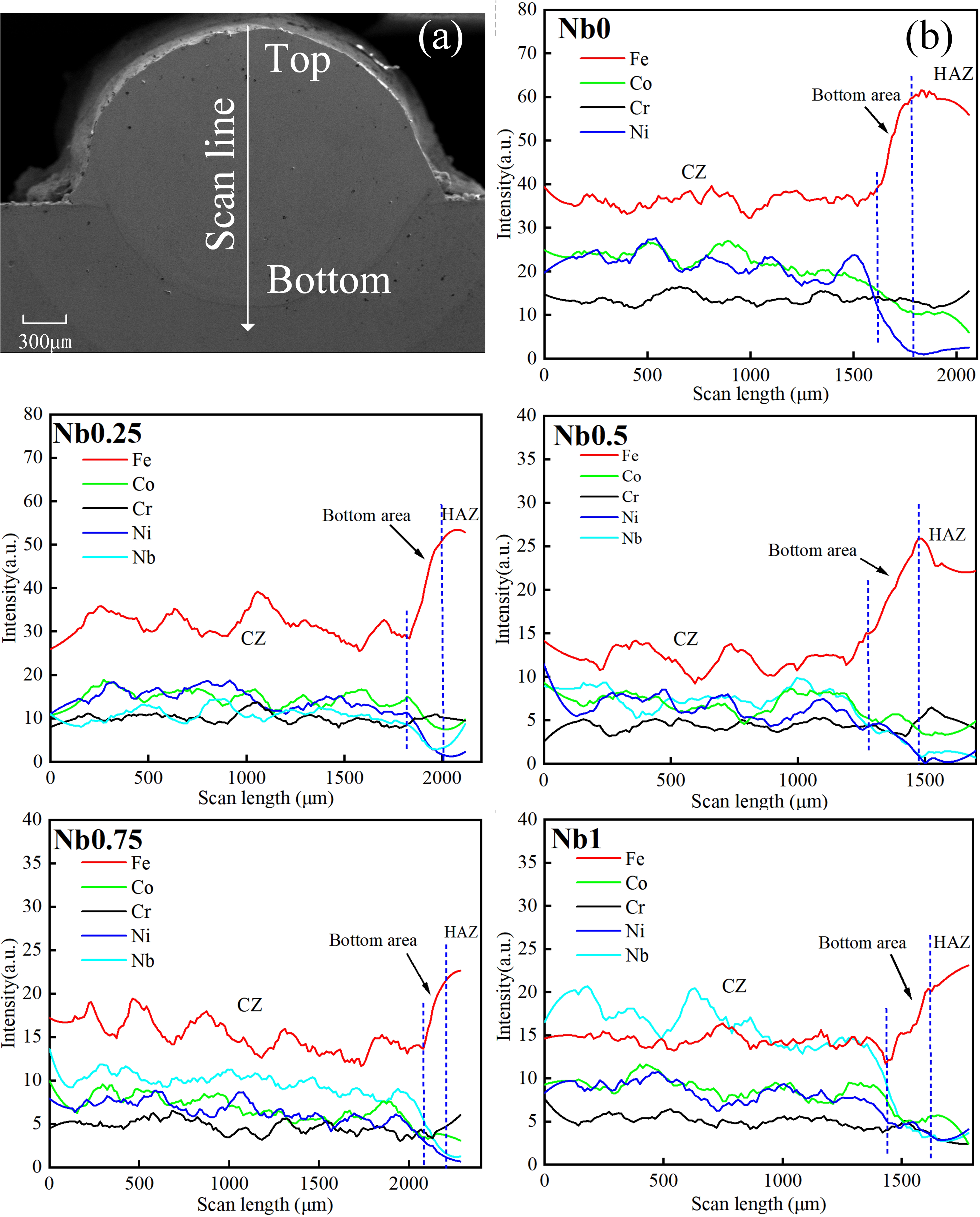
Element distribution of cladding layer: (a) scanning path diagram; (b) EDS scan curve.
Wear resistance
It can be seen from Figure 6(a) that there are grooves, flakes, spalling craters and wear debris on the surface of the friction layer. This indicates that the wear mechanism is adhesive wear and abrasive wear. The factors that affect the wear of the coating are mainly related to the hardness of the coating, and the appearance of the oxide layer will also affect the wear. During the friction process, the wear debris material is compressed and oxidised to form a hard oxide layer, as shown in Figure 6(b), which reduces the wear of the coating, acts as a lubricant 11 and reduces the plastic deformation caused by contact stress during the grinding process. Obviously, the microhardness of the substrate and the cladding layer with x = 0 is low, and the friction layer contains many spalling craters, indicating that adhesive wear is the main wear mechanism. Adhesive wear is caused by the gravitational force of the friction surface. Molecules at the interface form an adhesive bond with the contact surface, and the adhesive effect causes the surface of the friction pair to be destroyed, and the friction becomes rapid and intense. The amount of adhesion is related to the friction layer, Cr in HEAs is oxidised to form an oxide film, which reduces wear. However, due to the lack of sufficient Cr in the substrate, the oxide film formed by Fe is more prone to cracking and provides less protection to the metal. 12 After being pulled out or peeled off, the worn surface is ploughed during the movement, resulting in the appearance of grooves and spalling craters. For example, the image of CrFeCoNiNb0.25 coating in Figure 6(b) shows the flakes that are about to peel off, and after peeling off, it will form the spalling crater as shown in the image of Nb0. It should be added that when x = 1, thermal expansion leads to cracking. As the crack is small and narrow, it does not affect the anti-friction effect of the whole cladding layer.
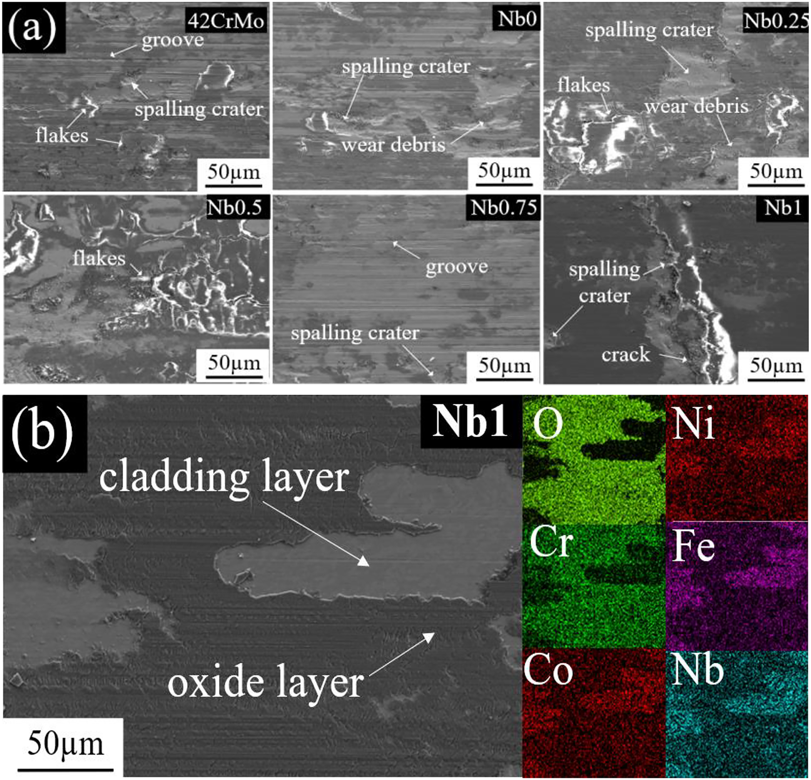
Wear morphology of the substrate and cladding layers: (a) SEM of wear morphology; (b) EDS of friction layer.
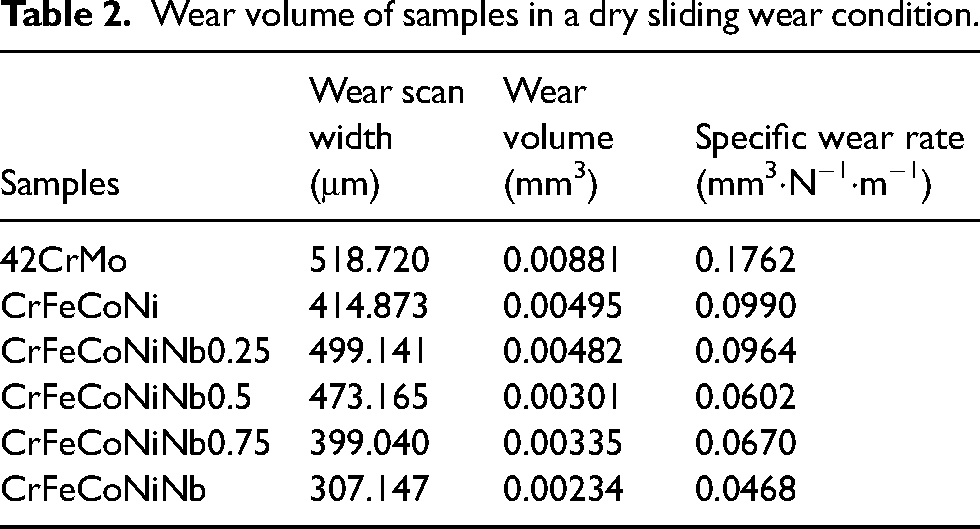
The wear scar width and the volume of the wear scar of the CrFeCoNiNbx cladding layers are shown in Figure 7 and these values are listed in Table 3. Both the wear scar width and the volume of the wear profile of the substrate are the largest, which indicates that the cladding layers provide a good level of wear resistance. The wear width and volume of the cladding layer exhibit an inverse relationship with the Nb content. The smallest wear scar width and volume are obtained in the cladding layers with x = 1, indicating that the cladding resistance is not affected by the presence of microcracks. This phenomenon is also related to the change in microhardness of different samples. The wear loss of the cladding layer is mainly caused by the microcutting of the hard friction pair. During the dry sliding process, the surface of the low-hardness coating has poor resistance to microcutting, which causes more wear debris to peel off. The coating with higher hardness has better resistance to plastic deformation, resulting in less wear.
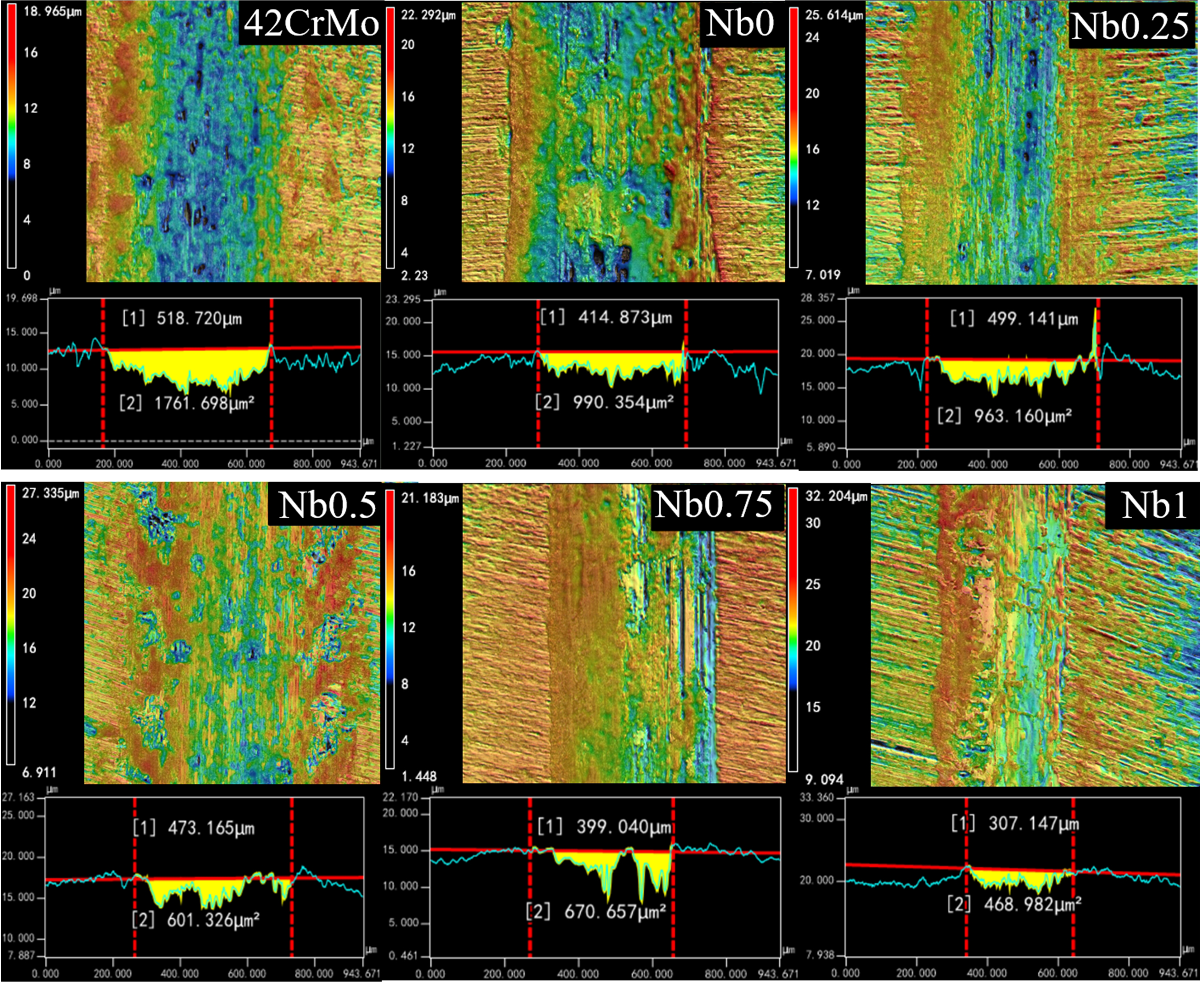
Observation of wear characteristics of CrFeCoNiNbx cladding layer and substrate using confocal laser microscope.
The relationship between microhardness and wear resistance is illustrated in Figure 8 According to the formula of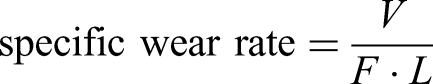
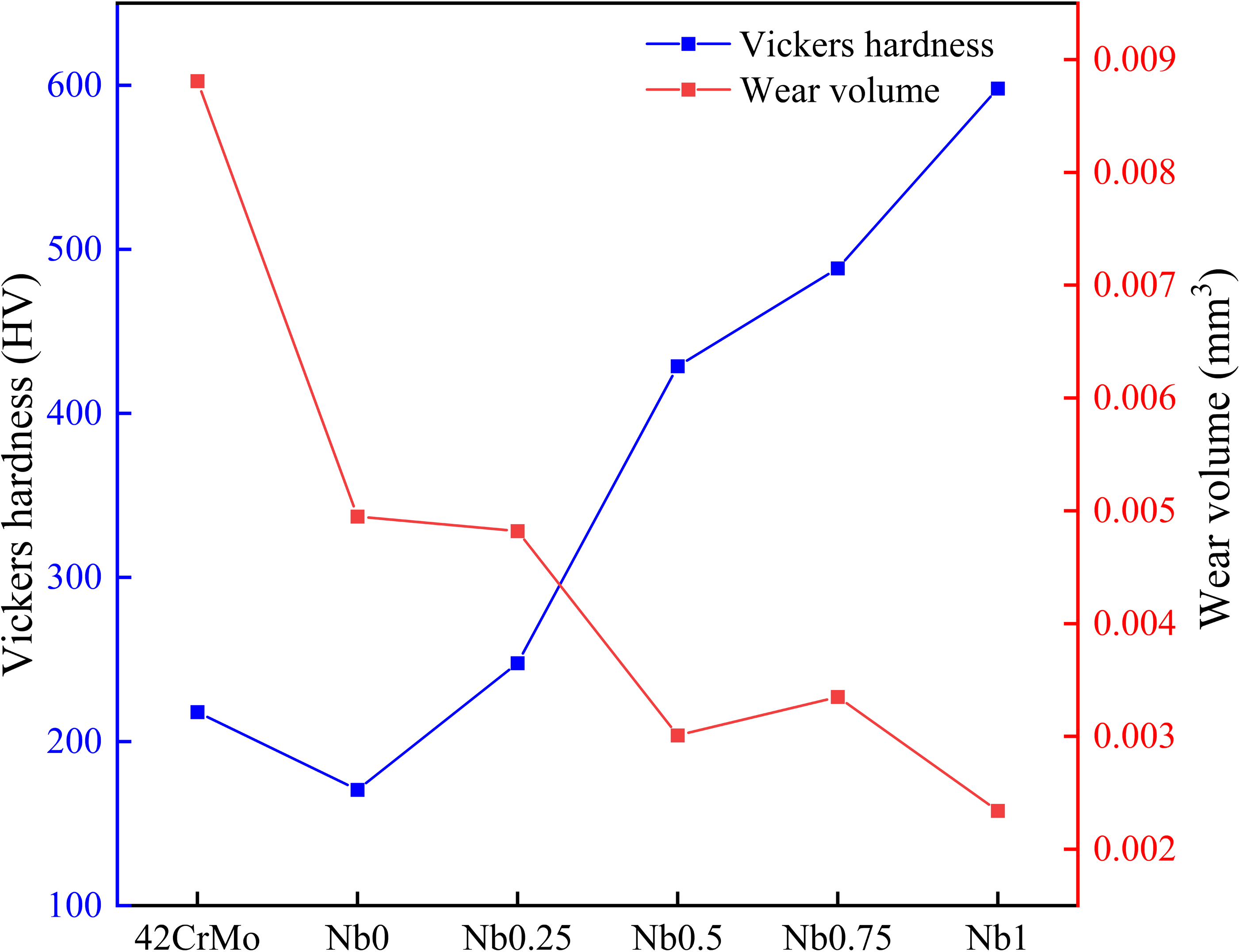
The relationship between microhardness and wear volume.
Wear volume of samples in a dry sliding wear condition.
Corrosion resistance
Using Zsimpwin software to simulate the equivalent circuit can help to understand the actual reaction of metal interface. Figure 9 provides the EIS results in 3.5 wt% NaCl solution as Nyquist plots soaked two hours in advance, the corresponding electrical equivalent circuit (EEC) used to fit the data is also provided. In the circuit simulation process, the capacitive reactance is represented by the constant phase elements (CPE). Due to the dispersion effect, the characteristic value of the CPE element will have a phase angle shift in a wide frequency range, so its characteristics are different from ordinary capacitive elements. The impedance value of CPE is defined by the following formula13,14: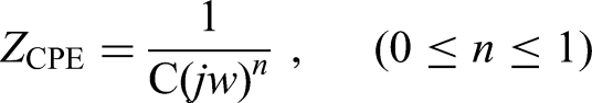
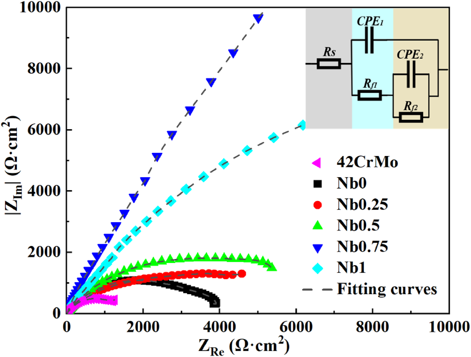
EIS tests as Nyquist plots and equivalent circuit of samples.
If the adsorption of solution molecules or the adsorption of some special atoms has a certain impact on the arrangement of atoms at the reaction interface, there will be a deviation between the CPE element and the ideal capacitance, and the value of n will change. When n = 1, CPE stands for pure capacitor element. When n = 0, CPE represents pure resistance. The EEC for fitting also includes
The polarisation curves of CrFeCoNiNbx cladding layers and 42CrMo in 3.5 wt% NaCl solution are shown in Figure 10 and Table 3 lists the polarisation data of the alloys. Evidently, 42CrMo and CrFeCoNiNbx cladding layers could be spontaneously passivated, in absence of an active-passive transition. However, the corrosion potential (Ecorr) of HEAs is more positive than that of the 42CrMo, and the corrosion current (Icorr) is lower. It is worth mentioning that there is no clear correspondence between the Ecorr and the corrosion resistance of the coating. But in general, the more positive Ecorr value represents the lower corrosion tendency. Since the Icorr is directly proportional to the corrosion rate, the small Icorr indicates a small corrosion rate when corrosion takes place at Ecorr. Moreover, the value of Rp is also proportional to the corrosion resistance of the alloys. It is not difficult to find that as the value of x increases from 0 to 0.75, the value of Ecorr moves forward the positive direction, the value of Icorr decreases, and the value of Rp increases. This finding suggests that the increase of the corrosion resistance is likely to be associated with the Laves phase. When x = 1, the existence of microcracks caused the continuity of the passivation film to be destroyed. Even if the Laves phase accounts for the largest proportion, it is inevitable that the corrosion resistance of Nb1 is slightly lower than Nb0.75.
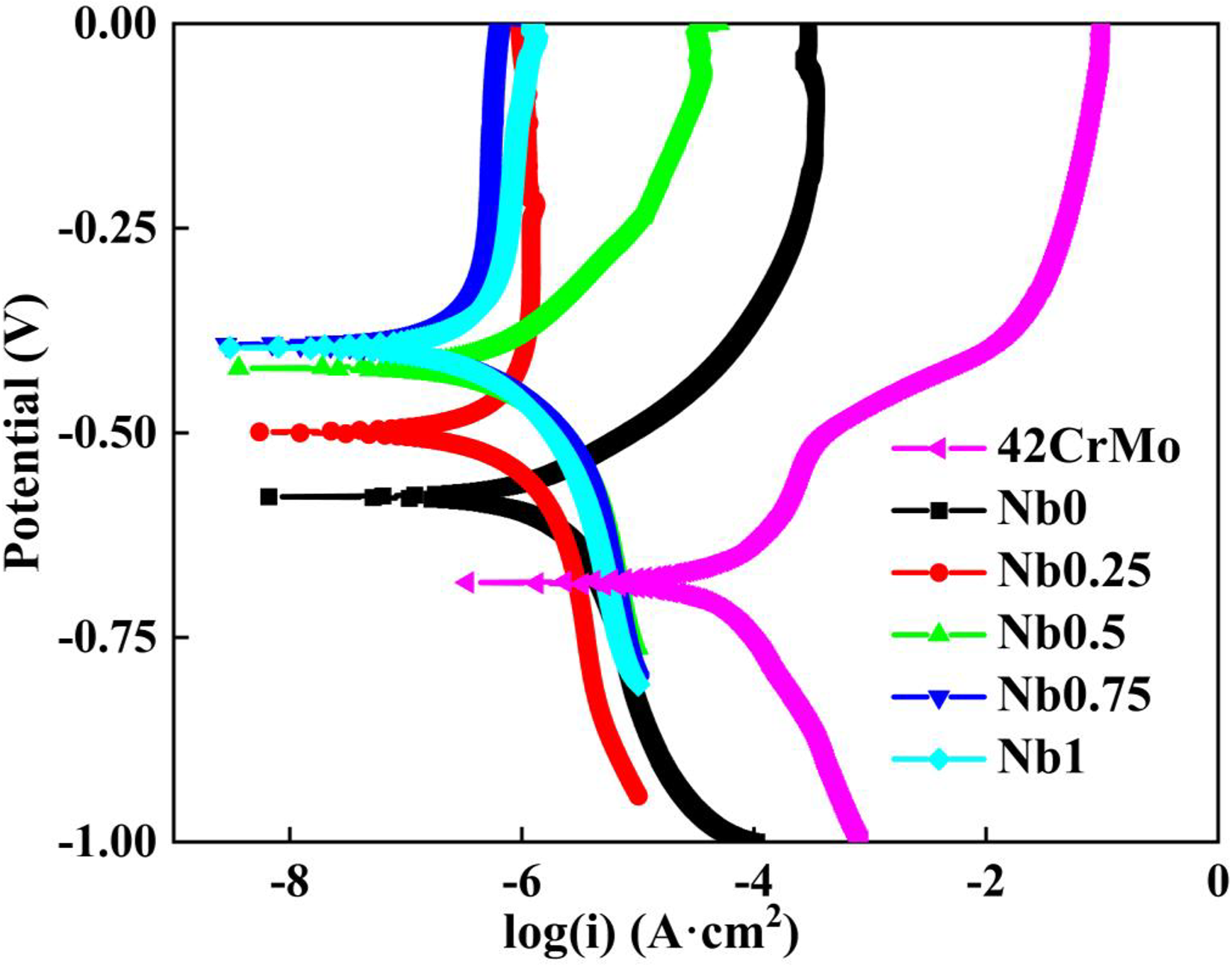
Polarisation curves of samples in 3.5 wt% NaCl solution.
Polarisation data of the alloys in 3.5 wt% NaCl solution.
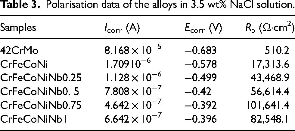
Figure 11 gives the morphologies of the samples after polarisation tests in 3.5 wt% solution. According to the EDS analysis, it is found that the substrate is extremely corroded and a large amount of agglomerated rust is formed. Local corrosion pits, corrosion holes and granular corrosion products appear on the surface of the cladding layer, which also shows that the cladding layer is relatively more resistant to corrosion. Generally speaking, the initiation process of pitting corrosion comes from intergranular corrosion and completes with pits formed by exfoliation of grains. When x = 0, combined with Figure 3, the analysis shows that the grain boundaries of the short rod-shaped protrusions are easily corroded, forming holes, and then forming pits. When x increases to 0.25, dendrites were more severely corroded than the interdendrites. Combined with the EDS results in Figure 5, Nb is mainly concentrated at the edge of the Laves phase, and there are almost no anti-corrosion elements in the grains relative to the intergranular region. This indicates that the Laves phase has stronger corrosion resistance than the FCC phase, which makes the grains easy to corrode. Since the Nb element has a strong solute drag effect, 13 it can effectively prevent the migration of the interface and form a non-equilibrium chemical boundary, 14 which acts as a good barrier and protects the Laves phase from being susceptible to erosion. When the value of x is further increased to 0.5, 0.75 and 1, Nb-Cr segregation occurs. Since the dendrites change to the Laves phase, and the dendrites almost retain their original shapes. The intergranular corrosion tends to occur at the element segregation first, and corrosion pits are formed along with the spalling of grains.
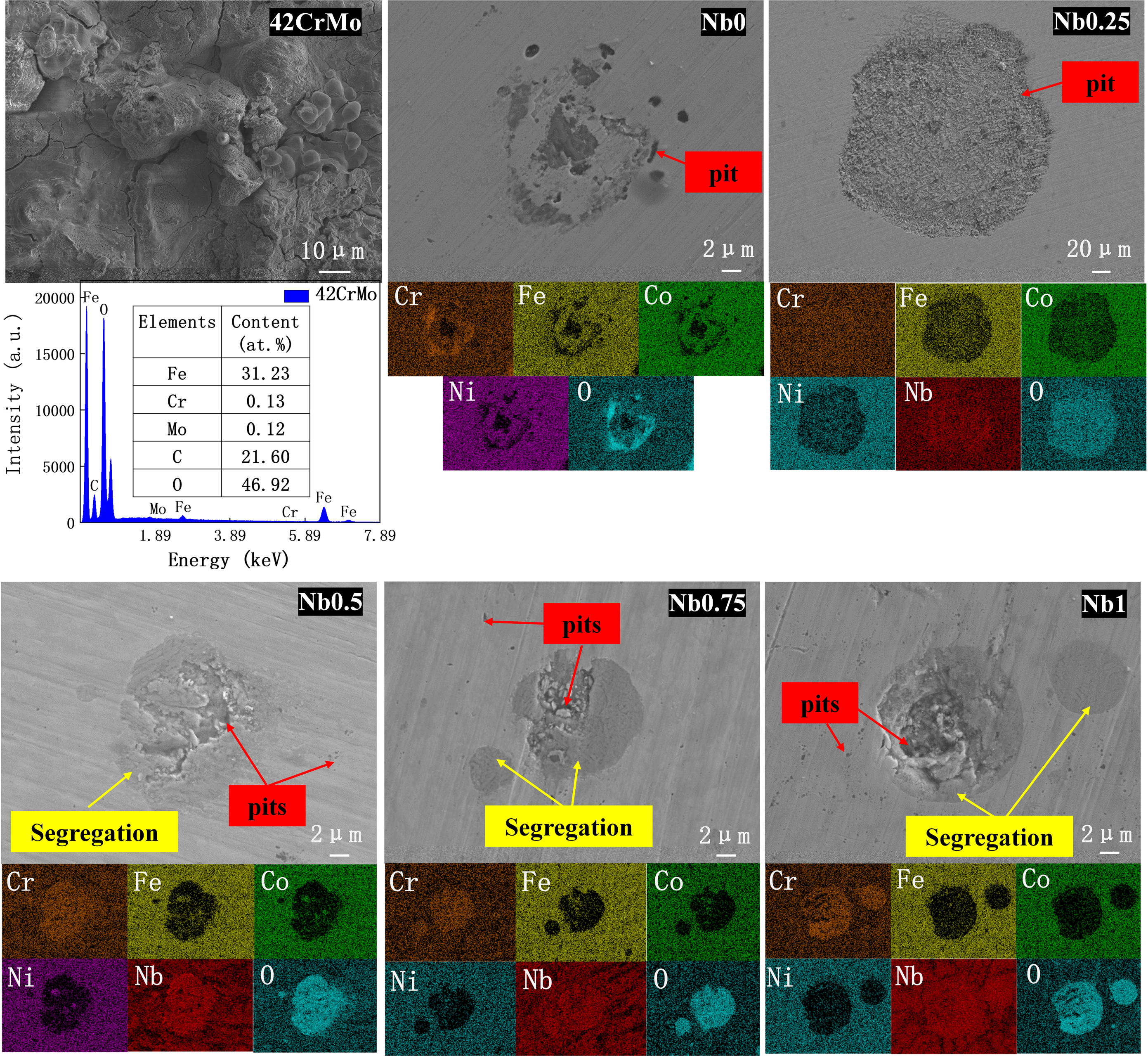
Corrosion morphology after polarisation of samples in 3.5 wt% NaCl solution.
Conclusions
Laser cladding technology and HEAs are combined to extend the service of stern shaft at lower cost. The following are the results of research on the properties of the CrFeCoNiNbx (x = 0, 0.25, 0.5, 0.75, 1) HEA cladding layer.
The addition of Nb promoted the transformation of the grain structure of the CrFeCoNiNbx cladding layer from FCC to FCC + Laves. Since the atomic radius of Nb element is larger than that of the other four elements, the extent of lattice distortion and proportion of the Laves phase increase with the increase of Nb. The microhardness of the CrFeCoNiNbx cladding layers increased with the increase of Nb, which were attributed to refine grain strengthening, solid-solution strengthening and the increase in the proportion of Laves hard phase. Wear resistance is generally proportional to microhardness and increases with the addition of Nb. It is noteworthy that when Nb content is low, the coating has a hardness similar to that of the substrate. However, due to the presence of an oxide film, wear resistance is improved. CrFeCoNiNbx cladding layers exhibited selective corrosion in 3.5 wt% NaCl solution. It mainly occurs between the FCC phase and the Laves phase, as well as the element segregation, which is related to the micro-galvanic corrosion. The three parameters (Icorr, Ecorr, Rp) in the polarisation indicated that the corrosion resistance of the cladding layer increases with the increase of Nb, which is mainly related to the increase in the proportion of Laves corrosion-resistant phase. The CrFeCoNiNbx cladding layer greatly improves the microhardness, anti-friction and wear resistance and corrosion resistance of 42CrMo, especially for the cladding layer with x = 0.75.
Footnotes
Declaration of conflicting interests
The authors declared no potential conflicts of interest with respect to the research, authorship, and/or publication of this article.
Funding
The authors disclosed receipt of the following financial support for the research, authorship, and/or publication of this article: This work was supported by the Shandong Provincial Natural Science Foundation (ZR2022ME081, ZR2021ME198), Collaborative Innovation Center for Shandong's Main crop Production Equipment and Mechanization (SDXTZX-21), and also it is Supported by the 111 project (No. D21017).