
Abstract
With the application of “λ” type composite skin becoming more and more extensive and diversified, its precise forming technology is also widely concerned. This article mainly solves the quality problems of “λ” type corner area, such as delamination dispersion and surface wrinkle, which exist in reality commonly in the manufacturing process. The prepreg is heated along the corner area of the tooling to solve the problem that prepreg is difficult to be compacted due to the large modulus of carbon fiber in “λ” type corner area. Furthermore, two precompaction tests are creatively increased at 16 layers (middle layer) and 32 layers (last layer) for the thick structure, respectively, to ensure the compaction effect of the blank. In addition, combined with the characteristics of highly elastic rubber and carbon fiber-reinforced materials, a new type of soft mold structure with proper flexibility and good stiffness is proposed innovatively through the reasonable placement of carbon fiber-reinforced materials and the setting of exhaust holes according to the structure characteristics of “λ” type root skin. Through further process verification, it is shown that the improved process has effectively solved the problems of wrinkles and internal delamination at the sharp corners of parts and realized zero-defect manufacturing of “λ” type root skin for the first time.
Keywords
Background
Compared with traditional structural materials, advanced composite materials are a new material with superior mechanical properties, such as high specific strength, high specific modulus, strong designability, good structural dimensional stability, and easy to form as a whole, and so on. 1 At the same time, their excellent performance can not only improve the service life of the aircraft structure and reduce the maintenance cost of the aircraft but also greatly reduces the number of parts and connectors, saves assembly time, and reduces the weight of the fuselage structure. 2,3 Therefore, composite materials that have played an important role since their inception are favored by aircraft structural designers and widely used in aerospace structures. Furthermore, they have become the mainstream trend of aviation manufacturing industry that composite materials were used to replace conventional materials such as metals and nonmetals. In addition, its dosage on aircraft structure is a symbol of the advancement of aircraft and an important guarantee for substantially improving aircraft performance. 4,5
Carbon fiber-reinforced resin composite is used as the manufacturing material for the root skin for leading-edge mobile flap, which was originally produced by a metal, to realize the lightweight, functional structure integration, and high performance of aircraft structure. However, as the flap root skin is a large-scale “λ” type structure with variable profile, curvature, and thickness, it is difficult to control molding quality for the part’s corner. In the actual engineering production process, defects such as wrinkles and internal delamination often occurred in the sharp corner of the part, and the defect diagram is shown in Figure 1.

The defect diagram: (a, b) Internal delamination defect and (c, d) wrinkle defect.
In view of the above problems, this article conducts the research on the precise forming of the root skin from the aspects of tooling structure, layup method, skin precompaction, and cover plate (soft mold) structure according to the structural characteristics of “λ” type parts synthesized by advanced composite.
Introduction to the “λ” type root skin for leading-edge mobile flap
Introduction to the structure of the “λ” type root skin for leading-edge mobile flap
“λ” type composite skin, as a typical aerospace composite structure, is widely used in aircraft structures. In this article, the root skin is a “λ” type structure with a deformed contour, variable curvature, and variable thickness, whose inner and outer profiles are some curved contours with assembly relationship, as shown in Figure 2.

The structural schematic diagram of “λ” type root skin: (a) top view of part, (b) front view of part, and (c) side view of part.
The upper and lower wings of the part are some irregular curved contours, the shape of the corner area gradually decreases from the root to the end, and the corner becomes sharper. The maximum length × width × height of the part is about 1500 × 120 × 400 mm3 and the maximum angle of “λ” type sharp corner is about 25°. In addition, the theoretical thickness of the parts is 3–4 mm and the surrounding area is the thickest.
Manufacturing process of the “λ” type root skin for leading-edge mobile flap
The manufacturing process of the “λ” type root skin for leading-edge mobile flap can be divided into tooling preparation, material preparation, processing cover preparation, laying and assembly, autoclave curing and demolding, and so on. The specific process flow is shown in Figure 3.

The manufacturing process of “λ” type root skin for leading-edge mobile flap.
Raw material of the “λ” type root skin for leading-edge mobile flap
The materials of “λ” type root skin for leading-edge mobile flap are bismaleimide resin (BMI) based on carbon fiber unidirectional belt ZT7H/QY9611 prepreg. The specific information is given in Table 1.
The physical properties of ZT7H/QY9611 prepreg.

Main technical and quality indicators of the “λ” type root skin for leading-edge mobile flap
Appearance quality: the contour of the part should be smooth and free of wrinkles. The sharp corner area should be well formed without significant fiber accumulation.
Internal quality: ultrasonic testing detects no defects, such as delamination, dispersion, and dense voids.
Thickness control: ± 5% of theoretical thickness.
The mechanical properties of the furnace parts meet the technical specifications of relevant materials.
Molding process improvement of “λ” type root skin for leading-edge mobile flap
Tooling design of λ” type root skin for leading-edge mobile flap
As can be seen from the side view of Figure 1, the internal contours of the root skin parts are relatively narrow through the analysis of the part structure. The maximum opening size of the part is only 120 mm. In addition, the closer the corner is, the smaller the opening is. If the female mold tooling is selected, the laying and forming process of parts will be very difficult. Therefore, the male mold tooling is finally selected as the forming mold of the parts.
In this article, the root skin contour has a large curvature and a certain number of local reinforced prepreg layers, which may lead to a misalignment of angle and position during the laying of prepreg. Furthermore, the misalignment of ply angle will have an important influence on the structural performance of parts. 6 –8 Hence, to ensure the accuracy of the layer angle and position, the laser projection equipment is used for positioning while adding the scribe lines of local reinforcement layer on the tooling surface, as shown in Figure 4.

The scribe lines of local reinforcement layer.
Since the outer surface of the root skin is an aerodynamic surface, a process cover plate (soft mold) is required to ensure the smooth and flat outer surface of the parts when male mold tooling is used to manufacture the parts. The process cover plate was often remade through the craft pieces. However, due to the structural characteristics of the process parts, there are a rebound angle and inaccurate positioning reference. When the process cover plate is manufactured, the springback angle and position deviation are generated on the basis of the process parts. This causes that the process cover plate cannot match the shape of the laminated composite blank completely and the pressure cannot be transferred to the blank effectively when curing, which further leads to some defects, such as delamination, dispersion, void, and so on. To solve these problems, this study uses digital molds to manufacture part shape tooling for the production of process covers. At the same time, to ensure the relative accuracy of the position of the process cover plate and the composite fiber layer, the locating pins of the cover plate with the same size of 1500 × 120 × 400 mm3 as the part are added in the same position of corner areas of part shape tooling and male mold forming tooling, respectively, as shown in Figure 5.

The locating pins of the cover plate.
Improvement of the laying process of prepreg
“λ” type skins, which generally have smaller size spans and fewer fiber layers, can be laid sequentially along with the tooling profile from the upper surface to the lower surface according to the traditional method, and then vacuumed and compacted. However, in this article, the largest length × width × height dimension of “λ” type root skin is about 1500 × 120 × 400 mm3, and the prepreg layers are up to 32. Moreover, the “λ” type corner is formed by the transition intersection of the two wing surfaces that are some irregular curved surfaces. Besides, the sharp corner area changes irregularly from the root to the end, which requires high laying skills for the operators. It is difficult to compact the prepreg in the corner area due to the large modulus of carbon fiber. After the prepreg is laid by the traditional method, there will be a rebound phenomenon of fiber, which leads to a risk of bridging in corner areas. To avoid the rebound of the fiber in the corner area, the method of “heating layup” is used to improve the forming process of “λ” type root skin. After the prepreg is fixed on the tooling by laser projection during laying, the prepreg at the corner area is first compacted. At the same time, to ensure that the prepreg at the corner area of the parts does not rebound, the prepreg is heated and compacted along the corner area of the tooling with the electric iron after manual compaction, which can help each layer of prepreg to be more closely attached to the tooling or the previous layer of prepreg, as shown in Figure 6.

The heating layup.
It is found that the problem of fiber rebound can be improved to a certain extent by heating and compacting the prepreg at the corner with the electric iron, and the compaction effect of the prepreg at the corner is more obvious with the increase of the temperature of the electric iron (the temperature is lower than 60°C).
Precompaction before curing “λ” type root skin
To ensure the molding quality of the root skin with a deformed contour and large thickness, the fiber layers are precompacted after the 16 and 32 layers were laid during the part manufacturing process. The precompaction process has two main functions: on the one hand, the volatiles in the billet and the voids between the layers are eliminated by the effect of vacuum and pressure, and the impregnation of the fiber by the resin is accelerated and improved so that the part basically reaches the predetermined thickness; on the other hand, when the resin viscosity reaches the minimum, the part blank should be precured at a lower temperature before curing in the autoclave. In this way, the curing reaction is slow, the molecular fluidity is good, the curing agent can fully react with the surrounding resin, many curing reaction centers are formed, and the network cross-linking density is relatively small. This further results in a more uniform internal network structure, small internal stress, and good performance of the matrix resin after final curing. 9 –11
In this article, the prepreg used for the root skin is ZT7H/QY9611, and the matrix is a typical BMI. It can be seen that the resin has the best fluidity near the temperature of 115°C from the viscosity–temperature curve of QY9611 BMI, as shown in Figure 7. Therefore, precompacting at the temperature of 115°C is conducive to the discharge of excess air bubbles and volatiles in the resin, which greatly improves the quality of part molding.
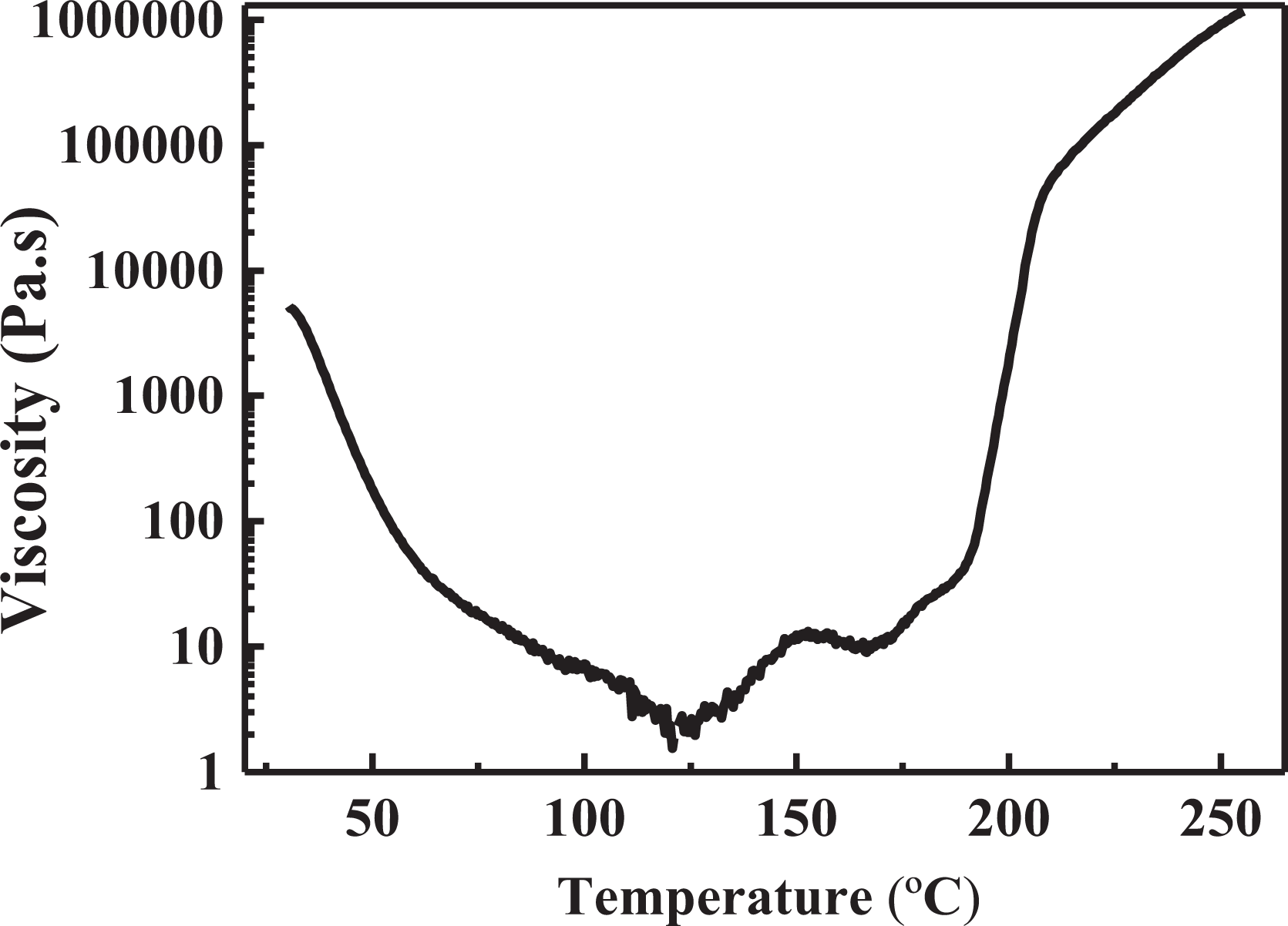
The viscosity–temperature curve of QY9611 BMI.
By adding two times of precompaction in 16 layers (middle layer) and 32 layers (last layer), respectively, the thickness of the part blank decreases by 0.2–0.5 mm compared with that of the uncompacted blank. Moreover, the forming quality of the blank is also greatly improved. The specific precompaction process parameters are as follows: The degree of vacuum is more than 0.09 MPa, and the pressure of 0.62 MPa is added, which can be ensured through the autoclave. The autoclave was produced by SCHOLZ, Germany, and the specification is SCH-3 × 6 m2. Heat the temperature to (115 ± 5°C) at a rate of 1.5°C min−1, keep the temperature for 15–20 min, and then release the pressure.
Improvement of soft mold process
When the “λ” type skin with sharp corners is manufactured with male mold tooling, the corner areas of the parts are usually wrinkled due to the restriction of fiber slippage during the curing process of parts. Therefore, to avoid uneven defects on the surface of the parts, a process cover plate for part curing shall be made according to the part shape tooling before manufacturing the part. However, there are two main problems for the general process cover plate: on the one hand, the hardness of the process cover plate is too large, which leads to have poor coordination with the mold and be difficult to form the products with complex shapes; on the other hand, the common soft mold is easy to form a closed cavity due to poor applicability with the blank, which causes poor internal quality and defects, such as delamination and dispersion after the part forming. In a word, if the soft mold is too hard, it cannot fit the surface of the parts while transferring the curing pressure, which leads to the surface quality that cannot meet the requirements. However, if the soft mold is too soft, it cannot effectively transfer the curing pressure while ensuring the fitting degree with the parts, resulting in the internal quality problems of the parts.
In this article, combined with the characteristics of highly elastic rubber and carbon fiber-reinforced materials, a new type of soft mold structure with proper flexibility and good stiffness is proposed innovatively through the reasonable placement of carbon fiber-reinforced materials and the setting of exhaust holes. The rubber soft mold can flexibly design the type, proportion, and dosage of fiber-reinforced materials according to the structural characteristics of the parts to obtain a structure with appropriate stiffness to better transmit and distribute curing pressure. Further, to improve the application of the soft mold and the blank and to avoid the formation of a closed cavity, the uniform exhaust hole can be added on the soft mold, which can not only ensure the applicability between the soft mold and the blank but also discharge the gas inside the blank.
The optimal soft mold structure of the root skin is obtained through the single variable method of factors, such as the type, proportion, and dosage of fiber-reinforced materials as well as the hole diameter and pore spacing of the exhaust holes. The specific test scheme is provided in Table 2.
Soft mold test scheme.

a Failure rate is the ratio of the number of parts with wrinkle defect and internal delamination defects to the total number of experiments.
As given in Table 2, the soft mold structure of scheme 12 is the best through the experimental analysis and effect verification. The cross-section view and the internal and external surfaces of the soft mold structure are displayed in Figure 8 and the layout of the exhaust holes is shown in Figure 9. As shown in Figure 8(a), the inner and outer surfaces of the soft mold are fully rubber plies. Besides, a whole layer of carbon fiber prepreg is laid on the inner rubber layer and the other two partial layers are evenly distributed on the corner area based on the centerline of the R area, whose widths are 60 and 40 mm, respectively.

(a) The cross-sectional view, (b) internal and (c) external surfaces of the soft mold.

The layout of the exhaust holes on the soft mold.
In addition, to avoid excessive stiffness in the corner area and to ensure the coordination and adaptability of the soft mold and the blank, the fiber prepreg in the soft mold is cut in the horizontal and vertical directions, which makes the soft mold to have appropriate stiffness and shaping ability. After the soft mold is formed, the exhaust holes with 3 mm diameter shall be made not only at the corner area but also at the other positions every 50 mm, as shown in Figure 9.
Evaluation of process improvement effects
The external and internal quality of the improved “λ” root skin are inspected, and the mechanical properties of the cocuring furnace parts are detected. 1) External dimension inspection
The external dimension of root skin is mainly the thickness measurement. The thickness is measured by Vernier caliper, and multiple measurement points are uniformly selected along the root skin. The measurement results meet the technical requirements and the thickness tolerance is within ±5%. 2) Surface quality inspection
The improvement effect of the surface quality of the part is shown in Figure 10, which suggests that the surface of the part is smooth and flat without obvious wrinkles and the corner area is well formed without obvious fiber accumulation wrinkles.

The improvement effect of the surface quality: (a, b) side view of part and (c, d) top view of part.
3) Internal quality inspection
The internal quality inspection of the root skin adopts the ultrasonic nondestructive inspection method. As shown in Figure 11, the internal quality inspection figures demonstrate that the parts have no internal quality problems, such as voids and delamination, detected by the Olympus-type phased array instrument.

The internal quality inspection diagram: (a) the nondestructive testing diagram of non-R area, (b) the corresponding testing result diagram, (c) the nondestructive testing diagram of R area, and (d) the corresponding testing result diagram.
4) Mechanical property inspection
The mechanical inspection of root skin with furnace parts includes bending test and shear test. The bending strength and interlayer shear strength test are carried out in accordance with ASTM D-7264 and ASTM D-2344, respectively. The equipment used in the mechanical performance test is produced by MTS Systems Corporation (Shenzhen, China), and the device model is E45.105. The parameters of sample used in the test are presented in Table 3 and the test results are presented in Table 4.
Parameters of the sample used in the test.

The test results of mechanical properties of root skin with furnace parts.

Conclusion
This article mainly solves the quality problems of “λ” type corner area, such as delamination dispersion and surface wrinkle in the manufacturing process. The prepreg is heated and compacted along the corner area of the tooling with the electric iron after manual compaction, which can help to solve inaccurate fiber angle and springback of the blank in “λ” type corner area. Especially, the large thickness structure creatively increases two precompaction at 16 layers (middle layer) and 32 layers (last layer), respectively, to ensure the compaction effect of the blank.
In addition, combined with the characteristics of highly elastic rubber and carbon fiber-reinforced materials, a new type of soft mold structure with proper flexibility and good stiffness is proposed innovatively through the reasonable placement of carbon fiber-reinforced materials and the setting of exhaust holes. According to the structural characteristics of “λ” type root skin, the rubber soft mold can flexibly design the type, proportion, and dosage of fiber-reinforced materials to obtain proper stiffness and effectively transmit and distribute curing pressure. The uniform exhaust hole can be added on the soft mold to improve the applicability of the soft mold and the blank and avoid the formation of a closed cavity.
To summarize, the process verification shows that the improved process has effectively solved the problems of wrinkles and internal delamination at the sharp corners of parts and realized zero-defect manufacturing of “λ” type root skin for the first time. Furthermore, the improved process has also been applied to the actual production process of “λ” type root skin. What is more, the conclusions will play an important guiding role in research field of the “λ” type structure forming process. It provides valuable theoretical basis and practical experience for the precise forming of “λ” type structure.
Footnotes
Author contributions
QG, KH, and YW conceived and designed the experiments; HX and QG performed the experiments; QG and KH analyzed the data; HX contributed reagents and materials; QG and KH wrote the paper and all authors read and approved the final manuscript.
Declaration of conflicting interests
The author(s) declared no potential conflicts of interest with respect to the research, authorship, and/or publication of this article.
Funding
The author(s) received no financial support for the research, authorship, and/or publication of this article.