
Abstract
Constrained layer damping treatment is widely used to suppress the vibration and noise of thin-walled structures. However, full coverage of constrained damping layer will increase unnecessary additional mass, resulting in material waste and cannot effectively improve the damping performance of the composite structure. In this article, a topology optimization approach is proposed to realize the optimal distribution of constrained damping layer. The design objective is to maximize modal loss factors solved by the modal strain energy method under the constraint of volume. Taking the relative density of the finite element of the constrained damping layer as design variable, the solid isotropic material with penalization method is used to realize the optimal topological distribution of the damping material on the surface of the metal substrate. Then the moving asymptote method is adopted as an optimizer to search the optimal layout of the constrained damping layer. Based on a modified modal superposition method, the sensitivities of the objective function with respect to the design variables are obtained. Numerical examples and experiments are presented for illustrating the validity and efficiency of this approach. The results show that the objective function converges to the optimal value smoothly, and the optimized modal loss factors have been significantly improved. The layouts of the constrained damping layer after optimization are clear and reasonable, and its distributions are affected by both the damping layer and the constraining layer. Each part of the constrained damping layer after optimizing can greatly improve the damping performance of the structure.
Keywords
Introduction
Thin-walled structures, represented by thin plates and shells, are increasingly used in power machinery shell structures, aerospace, ships, automobiles, and civil engineering structures. Due to its light and thin characteristics, it is more likely to cause vibration and noise under external excitation, which will cause damage to the accuracy, quality, reliability, and life of mechanical structure and cause vibration damage and noise pollution to the human body. 1 –3 Therefore, it is necessary to control the vibration of the thin-walled structures. Constrained layer damping (CLD) treatment is one of the most effective ways for suppressing noise and vibration in thin-walled structures. 4 –8 It consists in applying a viscoelastic layer covered by a much stiffer elastic layer onto the surface of thin-walled structures. The viscoelastic layer will undergo periodic shear deformation along with structural vibration and dissipate structural energy by using the phase difference between stress and strain in viscoelastic damping material, so as to achieve the purpose of reducing vibration and noise. The researches show that CLD treatment can effectively suppress the broadband random vibration response and improve the structural dynamic performance. 9 –12
The damping analysis of thin-walled structure with fully covered CLD treatment has been analyzed by many investigators using analytical or finite element methods. Kerwin 13 proposed a simplified theory for calculating the modal loss factors. The basis of the theory is to connect the shear strain of damping layer with the lateral motion of the structure. Xu et al. 14 established the theoretical model of the fiber-metal-laminated thin plate with CLD treatment based on the stress–strain relationships of the constrained layer, viscoelastic layer, and carbon fiber substrate and analyzed the vibration characteristics of the fiber-reinforced plate treated with CLD patches in different positions and shapes. Song and Hong 15 introduced a spectrally formulated finite element method for beams treated with CLD and pointed out that the spectral CLD beam element model can provide very reliable results compared with the conventional finite element model. Ross 16 studied the vibration problem of CLD-treated plate under simply supported boundary conditions by analytic method. Cupial and Niziol 17 established a dynamic analytical method for rectangular sandwich plate with general anisotropy of the face layers. Although analytic method can construct a framework that is brief and clear and can obtain accurate solutions of the CLD system, the solution of the equation usually depends on simple support structure and special boundary conditions. Therefore, the applicable objects are very limited and difficult to be used in practical engineering applications.
The finite element method can be used to calculate the dynamic characteristics of CLD-treated structures with various structural shapes and boundary conditions. 18 –21 Therefore, the finite element method is the most widely used methods for studying the vibration problem of thin-walled structures with CLD treatment and the achievements are also abundant. 22 Johnson and Kienholz 23 studied the vibration characteristics of sandwich composite beams using the modal strain energy (MSE) method and the finite element method. The modal loss factors are calculated using the modes of undamped systems. Ramesh and Ganesan 24 established the finite element dynamic model and carried out vibration and damping analysis of the CLD-treated cylindrical shell structure. Zhang and Sainsbury 25 studied the sandwich plate and improved the efficiency and accuracy of the finite element model by the Galerkin method. Yang et al. 26 used the finite element method to establish the dynamic model of the sandwich beam and used state-space method to solve the inherent vibration characteristics of the structure. Ren and Zhao 27 proposed a three-layer four-node quadrilateral finite element for CLD structures with complex structural forms and boundary conditions. Li et al. 28 presented a reduced passive CLD finite element model based on the first shear deformation theory and improved reduced system condensation method, and the frequency dependence of the viscoelastic materials is also considered. The proposed model can improve the calculation accuracy and reduce the CPU time. Zarraga et al. 29 presented a homogenized formulation to establish the dynamic finite element model of the CLD-treated plate, and this method has higher calculation accuracy and efficiency compared with the traditional method. Gupta et al. 30 established the finite element model and investigated the damping performance of a CLD-treated beam with graphite particles in the viscoelastic materials. Rouleau et al. 31 used the interface finite element method to model the thin constrained damping structure and proposed two kinds of interface finite element elements. One is the joint element which represents the relative displacement of the interface and the other is the element with zero original thickness. Zhao et al. 32 proposed a simplified single-layer equivalent method to establish the finite element model of the CLD-treated plate considering the shear and extension strains of all layers. This method can reduce the calculation cost and ensure the calculation accuracy. Joseph and Mohanty 33 established the finite element model of the CLD-treated plate based on the first-order shear deformation theory. The effects of core thickness ratio, aspect ratio, and volume fraction index on the buckling and free vibration of the composite plate at high temperature were investigated. In addition to the analytical method and the finite element method, the mesh free method has also been applied to the study of vibration analysis of CLD-treated structures. Sahoo and Ray 34 presented a mesh-free model based on the element-free Galerkin method to study the dynamics of the overall beam with CLD treatment.
In practice, the damping materials are often applied over the entire surface of the thin-walled structure for vibration suppression. However, in the design of the damping composite structure, the requirements of the lightweight and dynamic energy dissipation characteristics of the modern mechanical structure are increased. Therefore, the thin-walled structures need to be covered partially, as shown in Figure 1. It has been proved that many aspects, such as the thickness, position, and coverage area of the constrained damping layers, affect the damping effect of the structures. Lall et al. 35 studied the multiparameter optimal design of density, thickness, and temperature of constrained damping layers to maximize the structural modal damping parameters. Wang and Chen 36 investigated the damping of annular plates with fully and partially CLD treatment using a discrete layer annular finite element. Chia et al. 37 considered the use of cellular automata in conjunction with finite element analysis to optimize the layout of the CLD-treated plate, and the effectiveness of the optimization algorithm is verified by theoretical calculation and experiment. Assaf et al. 38 investigated the vibration and damping analysis of arbitrarily shaped base plates with fully or partially CLD treatment under various boundary conditions. Zheng et al. 39 established the dynamic model of partially covered CLD beam structure based on the energy method and optimized the position and length of the CLD patch and the shear modulus of the viscoelastic layer using genetic algorithm. Madeira et al. 40 applied the direct multisearch method for the design of CLD treatment panel for maximum fundamental modal damping and minimum added mass, by choosing the best distribution of the treatment patches on the surface of the composite panel. Alvelid 41 presented a design method for optimal positioning of attached constrained damping layers and demonstrated its purpose by examples. Chen and Huang 42 proposed a mathematical model of cylindrical shells with partial CLD treatment. The effects of treatment length, thickness and stiffness of constraining layer, and thickness of viscoelastic layer are discussed. Zheng et al. 43 proposed the CLD placement optimization of simply supported cylindrical structures under broadband harmonic excitation. The penalty function method based on genetic algorithm is used to optimize the location and geometric size of CLD patches with the minimum displacement response as the objective under the given constraint of the total amount of CLD used.
A plate with partially CLD treatment. CLD: constrained layer damping.
With the gradual maturity of structural topology optimization techniques, topological optimization methods such as solid isotropic material with penalization (SIMP) method, evolutionary structural optimization (ESO) method, and moving morphable component (MMC) method are applied to the design of CLD-treated structures to achieve optimal topological distribution of damping material. Zhing et al. 44 optimized the modal damping ratio of CLD-treated rectangle plate by using the SIMP method and method of moving asymptote (MMA). Fang and Zheng 45 established the topology optimization model of the plates by the ESO method and minimized the square of the vibration response peak under the specified frequency band excitation. Xie et al. 46 proposed a topology optimization design method of CLD-treated structures based on the MMC method and considered the frequency dependence of the viscoelastic materials. The kinetic energy of mechanical base structures in a certain frequency range is as the objective function, and the coverage area of constrained damping layer is as the constraint condition. At present, there are few researches on topology optimization of CLD-treated structures. As these structures are a multilayer composite structure with damping materials, the difficulty of topology optimization of the CLD-treated structures is higher than that of traditional structures. The inaccuracy of sensitivity calculation will lead to the oscillation of the optimization iteration process and the difficulty of convergence of optimization results. This will lead to the optimization result as relatively not optimal, which is one of the difficulties in topology optimization of the CLD-treated structures.
In this article, a topology optimization approach for the design of CLD-treated plate is proposed to realize the synchronous optimization of the viscoelastic layer and the constraining layer. The optimization model with the objective function of minimizing the reciprocal of modal loss factors is established using the SIMP method. The MSE method is used to estimate the modal loss factor from undamped normal modes. The sensitivities of the objective function with respect to design variables are obtained by a modified modal superposition method (MMSM). The rest of the article is arranged as follows. The second section introduces the governing equations of the vibrating plate and formulation for evaluating modal loss factors by the MSE method. In the third section, the topology optimization problem of the CLD-treated plate for maximizing modal loss factors is formulated, and the sensitivity analysis of the objective function and numerical implementation of the topology optimization program is also given. To illustrate the effectiveness and numerical efficiency of this method, several numerical examples of topology optimization of CLD-treated plates are given in the fourth section. In the fifth section, the feasibility and correctness of the proposed method are verified by experiments. Finally, the concluding remarks are provided in the sixth section.
Theoretical model
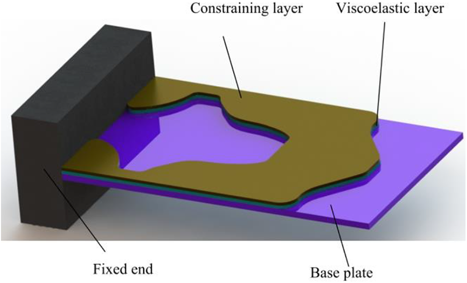
The plate with partially CLD treatment is shown in Figure 2. The upper layer is the constraining layer, the intervening layer is the viscoelastic layer, and the bottom layer is base plate. The constraining layer and the base plate are thin metal plate with high rigidity, while the intervening layer is viscoelastic material with low rigidity. The theoretical formulation is developed based on the following assumptions: (1) all displacements are small as in linear elastic theory, (2) all the layers are assumed to be isotropic and homogeneous, (3) the transverse shear strains in the constraining layer and the base plate are negligible, (4) no slip occurs at the layer interfaces, (5) the transverse displacements of all points on any cross-section of the CLD-treated plate are considered to be equal, and (6) the influence of moment of inertia is neglected.

Schematic of a plate with CLD treatment. CLD: constrained layer damping.
Geometry and displacements
The coordinate system and deformation of the CLD-laminated element are shown in Figure 3. In this article, each element has four nodes and each node has seven degrees of freedom to describe the longitudinal displacement of the constraining layer uc, vc, the longitudinal displacement of the base plate layer ub, vb, the transverse deflection w, and two rotational angles θx = ∂ω/∂y and θy = ∂ω/∂x. Based on Love–Kirchhoff theory, the displacements of the base layer and the constraining layer at any point inside the element in the x- and y-directions are as follows:

where u, v, and w are the displacement components in the x-, y-, and z-directions, respectively, and u0, v0, and w0 are the midplane displacements. z is the distance from the point to the middle surface, and δ is the thickness of each layer.

Degrees of freedom and geometric deformations of a CLD-laminated rectangular element. (a) Degrees of freedom and (b) geometric deformations. CLD: constrained layer damping.
According to the displacement relationships of each layer of the CLD-laminated element, the rotation angle around the y-axial of the viscoelastic layer is as follows:

The shear strains of the viscoelastic layer rotating around the y-axial can be given as follows:

where
The longitudinal displacement in the x-axial direction of the viscoelastic layer is as follows:

The shear strains of the viscoelastic layer rotating around the x-axial can be given as follows:

The longitudinal displacement in the y-axial direction of the viscoelastic layer is as follows:

Equations of motion
According to the linear theory of plate and shell structure, the kinetic energy and potential energy of each layer are derived by the normal strain and the shear strain. The laminated element kinetic energy is given by

where

The element potential energy is given by

where

Shear potential energy of the viscoelastic layer is defined as follows:

The global stiffness matrix and mass matrix are composed of the stiffness matrix and mass matrix of all laminated elements. According to the obtained global stiffness matrix and mass matrix, the finite element dynamic equation of the CLD-treated thin plate can be established. The matrices and dynamic equation can be written by


where x is the vector of displacement of any point inside the structure. M is the global mass matrix and f is the external mechanical force vector. KR and KI are the real and imaginary parts of the stiffness matrix. ηv is the loss factor of the viscoelastic materials.
Damping model
The damping mechanism of the CLD-treated structures is to convert vibration energy into heat energy for dissipation, and the structure loss factor is a key parameter to measure the energy dissipation of vibration. The complex eigenvalue method, the direct frequency response method, and the MSE method are the three main means for the dynamic analysis of composite structures with viscoelastic materials. The first two methods are calculated in the complex domain. Therefore, the calculation cost will be relatively high. The MSE method is based on the energy and the loss factors are defined as the ratio of dissipation energy to total deformation energy. The energies are calculated based on the modal shapes of undamped structural vibration system. Moreover, according to the shear strain energy distribution of the damping material, the position of the material that plays the main role in energy dissipation can be determined. Therefore, the MSE method will be used in this article. Based on the finite element model, the dynamic equations for free vibration of the CLD-treated plate has the following form:

where
The loss factor

where strain energy

Optimization problem formulation
SIMP interpolation scheme
The SIMP method is one of the most popular and effective method for topology optimization. In this article, the design domain of CLD-treated plate is discretized by square-laminated finite elements, each element e is assigned a relative density xe that determines its Young’s modulus Ee and material density ρ:

where
The layout design problem of damping materials is formulated as a size optimization problem on a fixed domain. In this study, the design domain is a fully covered CLD-treated plate. Then, the dynamic matrices of the laminated plate are then expressed based on the SIMP method as follows:

Optimization formulation
In this study, the objective of optimization design is to achieve the optimal topology distribution of constrained damping layers on the metal substrate surface under the premise of given material consumption, so as to give full play to the vibration suppression effect of viscoelastic materials under the requirements of lightweight. Modal loss factor is an important index to measure the ability of structural vibration suppression. The larger the modal loss factor is, the more effective the suppression of resonance amplitude is. There are many kinds of broadband harmonic excitation and random excitation in the actual environment of the structure, so it is of practical significance to suppress the vibration within a certain frequency bandwidth. Since the loss factor of viscoelastic material does not play a role in the calculation of modal vector of undamped free vibration equation, the influence of frequency dependence of the loss factor on the objective function is considered in the weight factor. Therefore, to effectively suppress the vibrations in a certain frequency range, the objective function can be defined as follows:
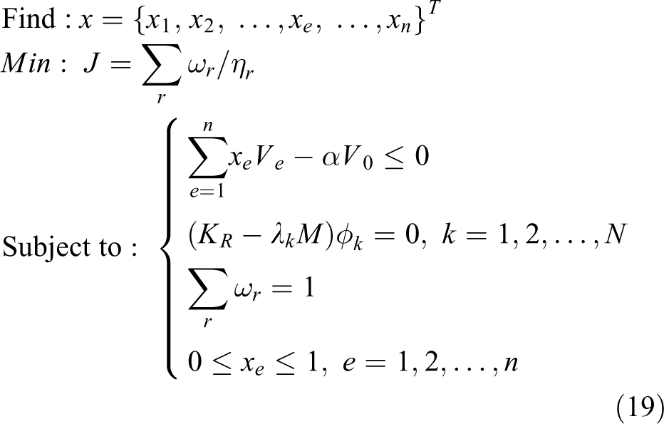
where Ve and V0 are the volume of the constrained damping layer of the laminated element e and the design domain, respectively. α is the maximum total fraction of CLD coverage. λr is the rth eigenvalue of the associated undamped system.
Sensitivity analysis
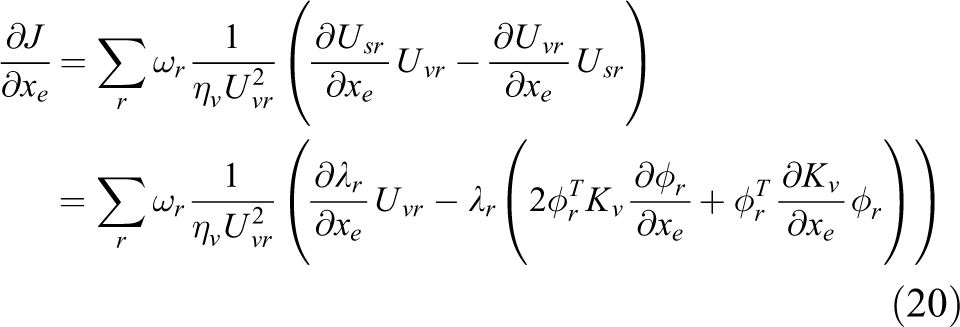
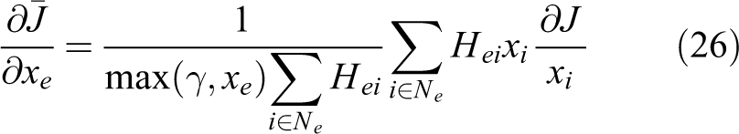
To solve the topology optimization problem, it is necessary to optimize the objective function value with the help of mathematical programming algorithm. Among them, the MMA method 47 has been proved to be universal and very suitable for large-scale topology optimization problems. The MMA method is based on the convex approximate asymptotic linearization method. This method is a convex approximation method based on the first-order Taylor expansion, the approximation function uses the first derivative of the original function at the current design point. By introducing moving asymptotes, MMA transforms the implicit optimization problem into a series of explicit separable strictly convex approximate suboptimization problems. In each iterations, the gradient class algorithm is used to solve the convex problem approximate subproblems to update design variables. For more details on this algorithm, see Svanberg’s works. 47 The key step to realizing the algorithm is sensitivity analysis, which can be described as the derivative of objective function with respect to design variable. Then, the sensitivity of the reciprocal of modal loss factor with respect to design variable xe (e = 1, 2,…, n) are given as follows:
For convenience, the eigenvector
Based on the MMSM, 48 the eigenvalue and eigenvector derivatives are, respectively, as follows:

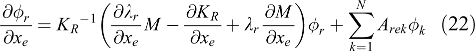
where N is the mode order which is much higher than r. Arek are coefficients for the modified modal method and can be calculated as follows:

According to the SIMP method, 49 the element mass matrix and stiffness matrix can be expressed as follows:


When the SIMP method is used to investigate topology optimization design problems, the inevitable numerical problem is the checkerboard pattern, which will lead to the optimized results cannot be applied to engineering practice. Sensitivity filtering or density filtering can effectively improve the problem, and Sigmund
50
has compared and summarized a whole range of filtering methods. In this article, the sensitivity
where Ne is the set of elements i for which the center-to-center distance D(e, i) to element e is smaller than the filter radius rmin. The term γ is a positive number introduced to avoid division by zero. Hei is a weight factor defined as follows:

Optimization strategy
The flowchart of the topology optimization procedures is shown in Figure 4. In this article, the MMA method is used to solve the topology optimization problem. First, the design variables xe (e = 1, 2…, n) are initialized to prescribed values. Then the stiffness matrix and mass matrix of the composite element are obtained according to the SIMP method. After assembly, the finite element dynamic model of the undamped free vibration of the CLD-treated plate is established. The eigenvalues and eigenvectors can be obtained by solving the above dynamic model. The objective function value of the corresponding eigenvalue is calculated by the MSE method. The first N eigenmodes are extracted to calculate the sensitivities of the objective function with respect to the design variables. To prevent checkerboard patterns, sensitivity filtering is applied. The MMA optimizer is used to update the design variables. If the objective function converges, the optimal layout of the constrained damping layers is obtained and the optimization iteration process is terminated. If the objective function does not converge or the number of the iteration is greater than the maximum value, the optimization process will be stopped.

Block diagram of the optimization procedure.
Numerical examples and discussions
Comparison of sensitivity calculation of the objective function
In Fang and Zheng,
45
topology optimization is only carried out for the viscoelastic layer in CLD-treated plate. It proposed that the modal vector

where

The MMSM uses a pseudostatic solution as an initial approximation to the mode shape derivative. This is similar in principle to the mode acceleration method used in transient structural analysis. The relative convergence of MMSM versus MSM for a given number of eigenvectors can be anticipated by dividing Eq. (23) by Eq. (29):
To ensure that the sensitivity calculation of the optimization objective function is accurate and efficient, the sensitivity values calculated by the above two MSMs are compared with the finite difference method (DFM). The form of the DFM is as follows:
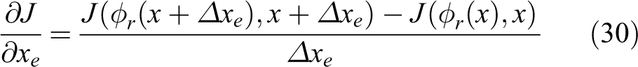
For the sake of reducing the numerical calculation error of the DFM, it is necessary to determine the step size of design variables reasonably. For this article, the step size of design variables is set to
Taking a CLD-treated plate with four edges simply supported as the research object, and the length and width of the plate are 0.3480 m and 0.3048 m, respectively. The design domain is discretized by 10 × 10 four-node rectangular finite elements. The thicknesses of the base layer, constraining layer, and damping material layer are 2 mm, 1 mm, and 1 mm, respectively. The initial values of the relative density of constraining layer and damping layer elements are set as xe = 0.5 (e = 1, 2,…, 100). After modal analysis, the first 40 modal vectors are extracted, and the sensitivity of the objective function is calculated by the MMSM and the traditional MSM, respectively. Then all the modal vectors are extracted for calculating the sensitivity values of the objective function with the traditional MSM. Finally, the sensitivity of the objective function is calculated by the DFM. The calculation results are shown in Figure 5. It can be seen that when the first 40 modal vectors are extracted for calculating the sensitivity of the objective function, the MMSM is consistent with the DFM, while the calculation deviation of the traditional MSM is large. When all modal vectors are extracted, the calculation deviation of the sensitivity using the traditional MSM is obviously reduced, but there is still a certain deviation. Therefore, the MMSM can effectively improve the efficiency and accuracy of the topology optimization of CLD-treated plate.
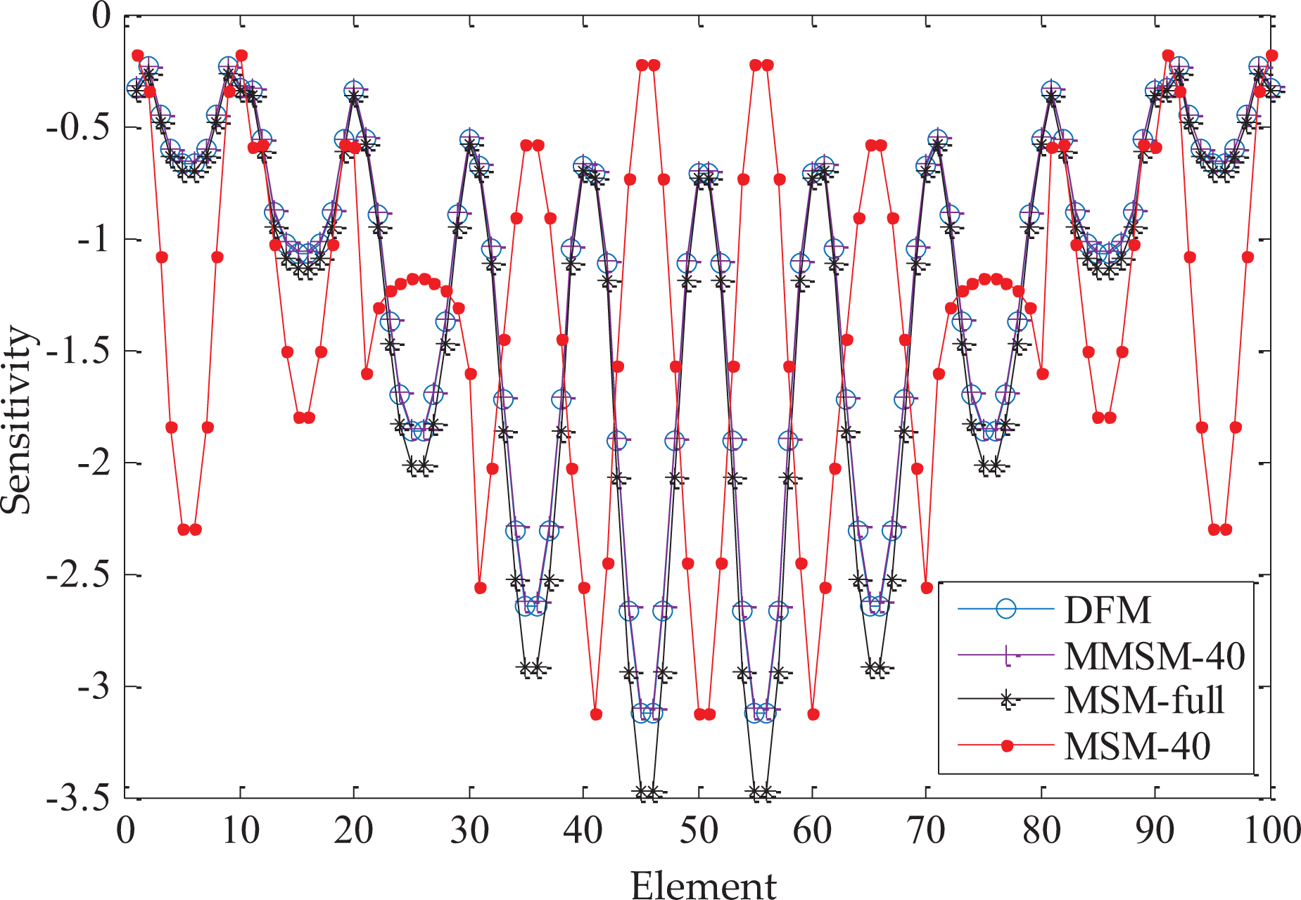
Comparison of sensitivities of the objective function with different calculation methods.
Single objective topology optimization for CLD-treated plate
This section presents two typical case studies to investigate the layout optimization design of CLD-treated plate for maximizing energy dissipation and illustrates the effectiveness of the proposed optimization program. Firstly, a sandwich cantilever plate is optimized to obtain the optimal distribution of the constrained damping layers for the first six modes under different volume fraction constraints. Secondly, a simply supported sandwich plate is optimized, and the optimal distribution of the constrained damping layers for different modes is obtained under the same volume fraction constraint. The frequency response analysis of the optimized partial covered CLD plate and the full covered CLD plate is carried out. In the optimization process, the optimal topology of constrained damping layers is solved by MMA approach. The volume fraction of the constrained damping layer is fixed as the constraint condition.
The first case study is a cantilever plate, which is shown in Figure 6. The upper surface of the metal substrate plate is taken as the optimization design domain, and the left end of the substrate plate is fully constrained with the rest of the boundaries is unconstrained. The length and width of the cantilever plate are L = 0.26 m and H = 0.2 m, respectively. The design domain is discretized by 40 × 30 four-node rectangular laminated elements. The thicknesses of the base layer, constraining layer, and viscoelastic layer are 2 mm, 1 mm, and 1 mm, respectively. The elastic base plate and constraining layer have the following material properties: elastic modulus E = 68.9 GPa, mass density ρ = 2740 kg/m3, and Poisson ratio μ = 0.3. Any damping introduced by elastic structural materials can be ignored because it is much less than that provided by viscoelastic materials. Shear modulus, mass density, Poisson’s ratio, and material loss factor of the damping material are given as Gv = 0.896 MPa, ρv = 1000 kg/m3, μv = 0.49, and ηv = 0.5, respectively. The frequency dependence of shear modulus and loss factor of damping materials are not considered in this article. The value of the elastic modulus of viscoelastic materials is obtained by its shear modulus and Poisson’s ratio as Ev = 2Gv(1 + μv).

The cantilever plate with left end fixed.
Table 1 presents the topology optimization results of the constrained damping layer of the sandwich cantilever plate for the first six modes under different volume fraction constraints. It can be seen that the optimal layout of constrained damping layer is different under different volume fraction constraint for the same eigenmodes. For the symmetric base plate, the layout of constrained damping layer is also symmetric. From the iteration history shown in Figure 7, it can be observed that the values of the modal loss factors rise steadily, the optimization processes converge after 30 iterations, and the modal loss factors of optimized structure are significantly improved compared with the initial structure. Figure 8 shows the modal loss factors of the first six modes after topology optimization under different volume fraction constraints. It can be seen that although the maximum values of modal loss factors can be obtained when the base plate is fully covered, the modal loss factor will grow at the most sluggish pace when the volume fraction is greater than 75% for the first, fourth, fifth, and sixth modes. When the volume fraction increases from 25% to 50%, the modal loss factors of each mode increase rapidly, while it will increase slowly when the volume fraction is greater than 50%. Figure 9 shows the strain energy distribution of the viscoelastic layer of the full covered sandwich plate for the first three modes. The red area indicates high MSE density, whereas the blue area indicates low MSE density. Figure 10 shows the MSE distribution of viscoelastic layer and constrained layer after optimizing the first modal loss factor. Figure 11 shows the MSE distribution of viscoelastic layer and constrained layer after optimizing the second modal loss factor, and Figure 12 shows those after optimizing the third modal loss factor. It can be seen that although the topological distribution of the constrained damping layer has changed significantly after optimization, the shear MSE distribution of the viscoelastic layer has little change compared with that before optimization. The optimized layout of the constrained damping layer is mainly distributed in the region of larger shear strain energy in the viscoelastic layer or the region with larger strain energy of constrained layer, which is beneficial to give full play to the energy dissipation property of damping material. It shows that the distribution of the constrained damping layer is affected by the shear strain energy of the viscoelastic layer and the strain energy of the constrained layer together. Therefore, the optimal layout of constrained damping layer cannot be determined only by the MSE distribution of viscoelastic layer or constrained layer.
Topology optimization of partially CLD treatment on the cantilever plate.


CLD: constrained layer damping.

Iteration histories of objective function value for the first six modes with α = 0.5.

Comparison of loss factors of the first six modes with different volume constraints.

Strain energy distribution of the viscoelastic layer of the full covered CLD-treated plate for the first three modes: (a) mode 1, (b) mode 2, and (c) mode 3. CLD: constrained layer damping.
Strain energy distribution of the viscoelastic layer and the constraining layer for the first mode after optimization: (a) viscoelastic layer and (b) constraining layer.

Strain energy distribution of the viscoelastic layer and the constraining layer for the second mode after optimization: (a) viscoelastic layer and(b) constraining layer.

Strain energy distribution of the viscoelastic layer and the constraining layer for the third mode after optimization: (a) viscoelastic layer and (b) constraining layer.

Frequency response of the CLD-treated plate and the bare plate excited by unit harmonic force at the same point. CLD: constrained layer damping.
Figure 13 shows the frequency response at the measured point of the optimized CLD-treated plate, bare plate, and full covered plate by applying unit harmonic excitation at the loading point. The optimized model for single mode has smaller frequency response in the current mode, which shows that the optimized constrained damping layer distribution has obvious suppression effect on vibration, and it can also effectively suppress the vibration in other frequency ranges. Compared with the bare plate, the partial coverage case and full coverage have almost the same vibration suppression effect, but the partial coverage case saves 50% of the material consumption of the constrained damping layer. It should be noted that the distribution of constrained damping layer will shift the resonance frequency of the whole structure. This is mainly due to the different effects of the added mass and the added stiffness on the resonance frequency. When the added mass is dominant, the resonance frequency moves to the left, and on the contrary, it moves to the right.
The second case study is a simple supported plate, which is shown in Figure 14. It is considered as the second case to test the effectiveness of the proposed optimization approach. The material properties are the same as applied in cantilever plate. The plate under consideration in this case study is 0.34 m × 0.3 m. For this case, the design domain is discretized by 34 × 30 four-node rectangular finite elements. The thicknesses of the base layer, constraining layer, and viscoelastic layer are 2 mm, 1 mm, and 1 mm, respectively. The volume fraction of the constrained damping layer is limited to half of the total design domain. The initial values of the design variables are set to be xe = 0.5 (e = 1, 2,…, 1020). The first 40 modal vectors are extracted to calculate the sensitivities of the objective function with respect to design variables.
Simply supported CLD-treated plate on four sides. CLD: constrained layer damping.
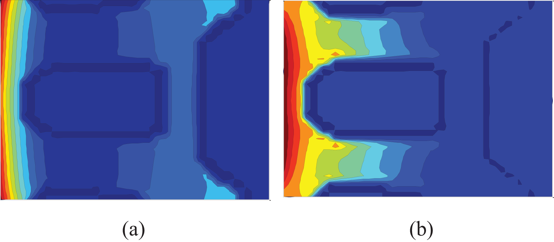
Figure 15 shows the optimal distributions of the constrained damping layer after optimization of the first, second, fourth, and fifth modal loss factors, respectively. Figures 16 to 18 present the MSE distribution of (a) viscoelastic layer, (b) constraining layer, and (c) base plate for the first, second, and fourth eigenmode, respectively. It can be seen that the constrained damping layer is mainly distributed in the region with larger shear strain energy of the viscoelastic layer, while the rest is distributed in the region with larger MSE of the constraining layer. This is principally because the constraining layer of this part plays a leading role in the distribution of shear strain energy of the viscoelastic layer, so it affects the modal loss factor greatly. After optimization, the MSE distribution of the constraining layer is consistent with that of the base plate, while the shear strain energy distribution of the viscoelastic layer is the opposite. Since the simply supported plate on four sides is a center symmetric structure, the obtained constrained damping layer is also center symmetric. Due to the structural symmetry of simply supported plates, the topological distribution of constrained damping layers is also symmetric. Moreover, it can be seen from the optimized results and energy distribution figures that when the first- and fourth-order modal loss factors are taken as the optimization design objectives respectively, there is symmetry between the two optimization results. The distribution of the constrained damping layer in Figure 15(a) is similar to the quarter of the symmetrical distribution in Figure 15(c), and the energy distribution in the corresponding area is also basically the same. It can be seen that the topology optimization program of the CLD-treated structure proposed in this article can also obtain the optimal distribution of the constrained damping layer of four-sided simply supported plates.
Optimized layout of constrained damping layers on the simply supported plate: (a) mode 1, (b) mode 2, (c) mode 4, and (d) mode 5.
The MSE distribution of each layer for the first eigenmode: (a) viscoelastic layer, (b) constraining layer, and (c) base plate. MSE: modal strain energy.

The MSE distribution of each layer for the second eigenmode: (a) viscoelastic layer, (b) constraining layer, and (c) base plate. MSE: modal strain energy.

The MSE distribution of each layer for the fourth eigenmode: (a) viscoelastic layer, (b) constraining layer, and (c) base plate. MSE: modal strain energy.
Multiobjective topology optimization for CLD-treated plate
This case study focuses on topology optimization of CLD-treated thin plate for multiple objectives, so as to achieve vibration suppression within a certain frequency bandwidth. The cantilever plate is still used for research. The geometric parameters, material properties, and finite element mesh density of the structure are the same as those in the previous single-objective optimization. For convenience, only the first three modes are of interest. The volume fraction ratio of the constrained damping layer is restricted by α = 0.5. The first 40 eigenmodes are involved in the computation (i.e. N = 40).
Figure 19(a) shows the optimized topology of constrained damping layer when the weight factors are

Optimized topology of constrained damping layer on the cantilever plate under different weight factors. Case 1:
Frequency response of the three cases CLD-treated plate, bare plate, and full covered plate. CLD: constrained layer damping.
Experimental verification
To verify the correctness of the topology optimization model and algorithm, the optimized results of the first and second eigenmodes are taken as examples to make the CLD-treated plate test piece. The three-dimensional design software is used to reconstruct the optimized model and then the laser cutting method is used to process the constraint layer metal plate. Because of the low rigidity, the viscoelastic layer is processed by cutting. The experimental models are shown in Figure 21. The vibration test platform and testing principle are shown in Figures 22 and 23, respectively. The vibration test system includes hammer, laser Doppler vibrometer, learning management system (LMS) data acquisition front end, mobile workstation, fixture, vibration table, and modal analysis software. The process is as follows: (1) The CLD-treated cantilever plate is fixed on the vibration table by the fixture; (2) the hammer produces an excitation signal by striking the surface of the composite plate; (3) the laser vibrometer is used to test the vibration acceleration response of the composite plates; and (4) the LMS data acquisition mobile front end transmits the collected response signals to the mobile workstation and then the analysis software processes the response signal and outputs the result. The experimental tests are carried out on the full coverage CLD-treated plate, bare plate, and the above two optimized partially covered CLD-treated plate. The positions of the excitation input points and the response output points of the four plates are, respectively, consistent. Figure 24 shows the experimental results of the frequency response of acceleration. It can be seen that the topological distribution of the constrained damping layer obtained after optimization of the first-order modal loss factor is closer to the full coverage on the resonance peak of the frequency response at the first-order natural frequency, and similar results can be obtained for the second eigenmode. In the simulation analysis, the shear modulus of the viscoelastic layer material is 4.5 MPa, the loss factor is 1, and the loss factor of base metal plate is 0.008. Figure 25 shows the simulation results of the frequency response of acceleration. It can be seen that the frequency response functions of simulation and experimental tests are basically consistent. The small difference is mainly due to the failure to consider the frequency dependence of the loss factor and shear modulus of viscoelastic materials. Table 2 presents the comparison of the resonance response amplitude and difference rate of the first two modes of the CLD-treated plate and the bare plate. Due to the loss factor of the bare plate is also frequency-dependent and the damping is very small, the frequency response function of the bare plate calculated theoretically is quite different from that measured experimentally. Therefore, in the calculation of difference rate of simulation results, the resonance response amplitude of the bare plate is replaced by the experimental data. It can be seen that although the material consumption of the optimized partial covered CLD-treated plate is only half of the total coverage, the damping effect is basically the same. This shows that the method proposed in this article is accurate and reliable and can be applied to the actual project.
The resonance amplitude and the difference ratio between the CLD-treated plate and the bare plate.

CLD: constrained layer damping.

The experimental models of the two optimized CLD-treated plate: (a) the first eigenmode and (b) the second eigenmode. CLD: constrained layer damping.

Vibration test platform of the CLD-treated plate. CLD: constrained layer damping.
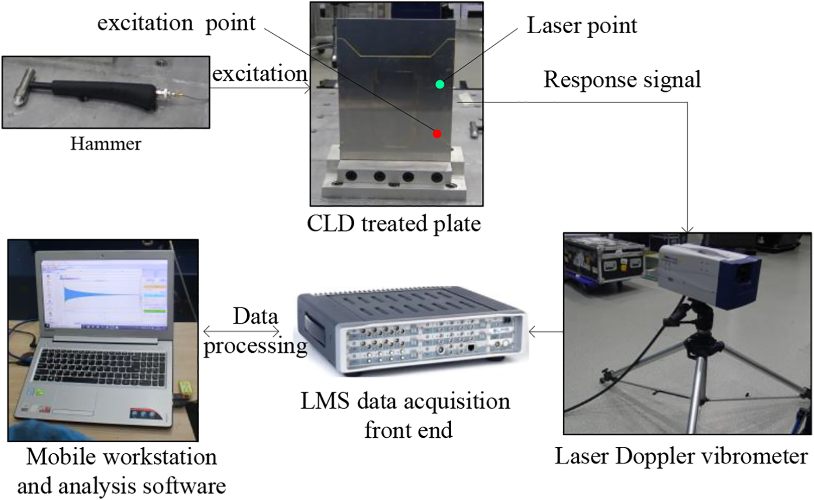
Schematic of vibration test system of the CLD-treated plate. CLD: constrained layer damping.

Comparison of the frequency response by experimental test.

Comparison of the frequency response by simulation analysis.
To study whether the test mode shapes is consistent with the theory mode shapes, for convenience, only the cantilever plate model in Figure 21(a) is taken as the research object in this article. Table 3 presents the comparison of the first four order mode shapes and natural frequency from experimental test and theoretical calculation. It can be seen that the mode shape from te experimental test is consistent with that of theoretical calculation. However with the increase of the frequency, the deviation between the theoretical value and the actual value of natural frequencies will be larger. This shows that the proposed method can also obtain feasible optimization results without considering the frequency dependence of elastic modulus of viscoelastic materials but will make the natural frequency shift.
Comparison of mode shapes and natural frequencies from experimental test and simulation analysis.

Conclusion
This article has presented a topology optimization approach of CLD-treated thin-wall plates for maximizing modal loss factors. Based on the SIMP interpolation scheme, the stiffness matrix and mass matrix of the constrained damping layer with respect to element relative density are obtained. The sensitivity analysis of the objective function is developed based on an MMSM. The gradient-based MMA optimization algorithm is used to update the design variables. The results of the numerical examples and experiment research show as follows: The efficiency and accuracy of sensitivity analysis of the objective function are discussed. In the process of calculating the sensitivity of the objective function, the sensitivity of the modal vector needs to be considered. The MMSM can obtain higher calculation accuracy of the sensitivity of the modal vector by extracting fewer number of modes and improve the calculation efficiency. This shows that the approach proposed in this article is effective and reliable. The multiobjective topology optimization for CLD-treated plate can effectively suppress the vibration within a certain frequency bandwidth with restriction of weight. This shows that the approach proposed in this article has practical significance. The objective function converges to the optimal value stably, and the optimization results are clear and easy to reconstruct. The experimental results are consistent with the simulation results. The above results show the effectiveness and practicability of the present approach. The amplitude of resonance response of the structure mainly depends on the damping of the system. The resonance can be effectively suppressed by increasing the modal loss factor of the system. The multiobjective topology optimization method of CLD-treated plate proposed in this article is to achieve effective suppression of resonance response within a certain frequency bandwidth by optimizing multiple modal loss factors. The value of the weight coefficient in the objective function depends on the frequency dependence of the loss factor of damping material and the relative magnitude of resonance response suppression effect at different modal frequencies. This article does not consider the frequency dependence of elastic modulus of viscoelastic materials. It can be seen from the experimental results that not considering the frequency dependence of elastic modulus of the damping material does not lead to invalid optimization results but only leads to a small shift of the modal frequency. This shows that when the modal shape of the CLD-treated plate does not change, the distribution of constrained damping materials will be basically the same. Therefore, this approach proposed in this article is more suitable for topology optimization of CLD-treated plate in a narrow frequency bandwidth.
In this article, the variation of mechanical properties of viscoelastic materials with frequency and temperature is not considered. Therefore, it is of great practical significance to consider the frequency or temperature dependence of viscoelastic materials in the optimization process, especially in the need to consider the frequency offset and the optimization of modal loss factors in a broadband frequency range. When the frequency dependence of the elastic modulus of viscoelastic materials is considered, the dynamic system is nonlinear, and the topology optimization of CLD-treated thin-walled structures cannot be carried out based on the MSM of linear system. The difficulty of topology optimization of nonlinear vibration system lies in the complexity of the derivation of the sensitivity formulas, slow convergence speed, and the large amount of calculation. This will be an urgent problem in this field. At the same time, the topology optimization considering the dynamic response of CLD-treated structures under complex boundary conditions and wideband acoustic vibration environment is worthy of further study. Furthermore, the current research mainly focuses on the optimization of plate structures, and the future research will be extended to the shell structures.
Footnotes
Acknowledgements
Special thanks to Prof. K. Svanberg of the Royal Institute of Technology in Stockholm for supplying the Method of Moving Asymptotes code.
Declaration of conflicting interests
The author(s) declared no potential conflicts of interest with respect to the research, authorship, and/or publication of this article.
Funding
The author(s) disclosed receipt of the following financial support for the research, authorship, and/or publication of this article: This research was funded by the National Natural Science Foundation of China (Nos 51975567 and 51505470), State Key Laboratory of Robotics (Y7A1207301), and Youth Innovation Promotion Association, CAS (2018237).