
Abstract
Aiming at the problem that the vibration of the space science experimental cabinet is too large during the launch phase of the rocket, the viscoelastic constrained damping layer is used to suppress the vibration. Firstly, to explore the vibration suppression mechanism of the constrained damping layer, the dynamic model of the constrained damping layer is established and the modal loss factor is calculated. Secondly, the influence of the modulus, material thickness, and the position and the area of the damping layer on the loss factor of the structure is analyzed. Finally, the simulation and experiment methods are used to calculate and verify the space science experiment cabinet with additional constrained damping layer. The results show that the viscoelastic constrained damping can effectively reduce the vibration level of the space science experiment cabinet, and the acceleration response in the resonance region is reduced by more than 56%. The viscoelastic constrained damping structure is simple and easy to realize, which can suppress the vibration of the space payload design is of great significance.
Keywords
Introduction
During the phase of the launch vehicle, the space science experiment cabinet will experience the impact of the dynamic environment. The biggest problem is that the vibration response is too large, which will lead to a significant reduction in the reliability of the structure and even lead to major safety accidents. Therefore, it is so important research direction to restrain vibration and improve the resistance performance of the space science experiment cabinet.
Constrained damping layer is a kind of structure in which viscoelastic damping material is laid between base plate and constrained layer (usually metal plate) with large rigidity. 1 –3 It is a feasible method to add viscoelastic constrained damping layer on the structure, especially in the resonance region. Laying viscoelastic damping material can greatly reduce the vibration level. For example, the original structure of the mounting plate of a satellite attitude control element is fiber composite plate, and the vibration response at the resonance frequency is greatly reduced by the additional constrained damping layer. 4 –6 For the conical shell structure, the vibration response of the additional constrained damping layer is calculated by the finite element iteration method, and the position of the constrained damping layer of the shell structure is studied. The results show that the constrained damping structure can effectively reduce the vibration response, and the effect of the constrained damping placed in the neutral plane is the best. 7 –10 In addition, the constrained damping layer belongs to composite structure. For the study of vibration characteristics of composite structure, scholars at home and abroad have done a lot of research. 11 –17 Rao 18 analyzed the constrained damping beam with initial stress by using residual deformation beam element and solved the modal loss factor by using direct frequency response method. Johnson and Kienholz 19 introduced a modal strain energy method, which combined with deformation energy analysis to determine the modal loss factor. Adding constraint damping to the existing spacecraft structure will increase damping effect of the structure, improve the stiffness and mass of the structure, and deduce the law of vibration suppression in the process of attitude maneuver. The experimental results show that this method does not change the structural characteristics of spacecraft, it is simple to apply and has good restraining effect. Zhou et al. 20 tested and verified the damping effect of the additional constrained damping layer of the satellite transition support, and the results showed that the acceleration response was reduced by 15.1–16.1%. Bisheh H and others 21 –25 have carried out a series of studies on the composite cylindrical shell structure, put forward a complete mathematical model to evaluate its mechanical behavior, and analyzed the wave behavior under different working conditions such as humid and hot environment and polarization, which can be used for dynamic stability assessment and health monitoring. Luo et al. 26 designed a kind of space damping truss, which effectively reduced the vibration response of the space truss by using the method of long pipe breaking and laying the constrained damping layer. In the current research literature, the frequency dependence of damping materials has not been considered in the modeling of constrained damping structures, and no scholar has adopted constrained damping structure vibration reduction methods to reduce the vibration response of the space science laboratory cabinet.
In this article, aiming at the problem that the vibration of the space science experiment cabinet is too large, which leads to the decrease in the reliability of the structure, the viscoelastic constrained damping layer is proposed to suppress the vibration of the space science experiment cabinet, and the mechanism of the constrained damping is studied. Through the simulation and experimental verification, the feasibility and superiority of using viscoelastic constrained damping layer to suppress the vibration of space payload system are proved.
Dynamic model establishment and experimental verification of constrained damping layer
Figure 1 shows the structure of the constrained damping layer, which is composed of two materials: metal base layer, constrained layer, and butyl rubber damping layer.

where

Constrained damping layer.
Since the elastic modulus of constrained damping layer is expressed by complex modulus, the finite element dynamic equation of the system is:

where M is the mass matrix of the system;
The real part and the imaginary part of the complex stiffness matrix can be further expressed as:


where
Complex eigenvalue method
For the complex eigenvalue method, the complex stiffness matrix

where

where
Therefore, the rth modal loss factor

Compared with the real eigenvalue calculation of undamped system, the calculation time is long and the calculation cost is high.
Modal strain energy method
For the classical modal strain energy, because the real elastic modulus of viscoelastic damping material is smaller than that of metal damping material, only 0.0001 to 0.00001 times of the latter, so the real part of the complex stiffness matrix

where
Then, the loss factor of the rth mode is derived:

where
Compared with the complex eigenvalue method, the calculation amount of modal strain energy method is greatly reduced. And some general finite element software can realize the solution of this method, ignoring the lag effect of viscoelastic materials on the vibration mode of the structure.
Examples and experimental verification
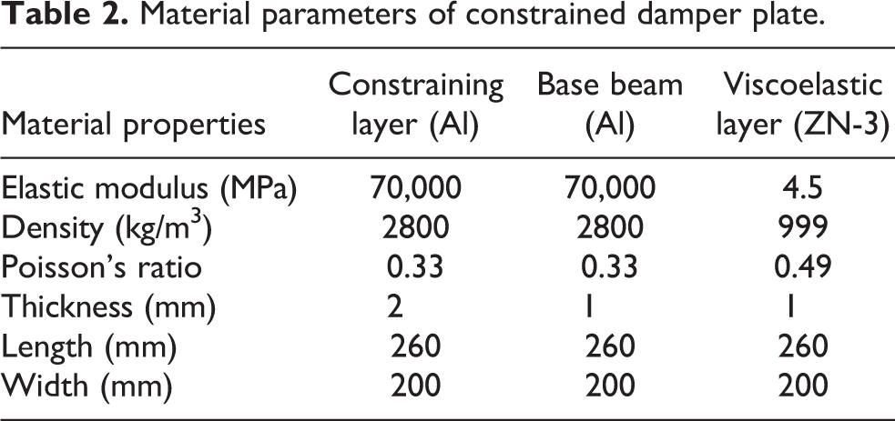
To verify the accuracy and reliability of the proposed of the structure modeling of constrained damping layer, the constrained damping layer under the cantilever boundary condition is taken as the research object, and its dynamic characteristics are calculated. The structure of constrained damping layer is shown in Figure 2. Among them, butyl rubber ZN-3 material is used as damping layer, and the mechanical performance parameters are measured by dynamic mechanical analysis, as presented in Table 1. Aluminum is used as base and constraint layer, and material parameters and geometric dimensions of each layer of constraint damping structure are presented in Table 2.
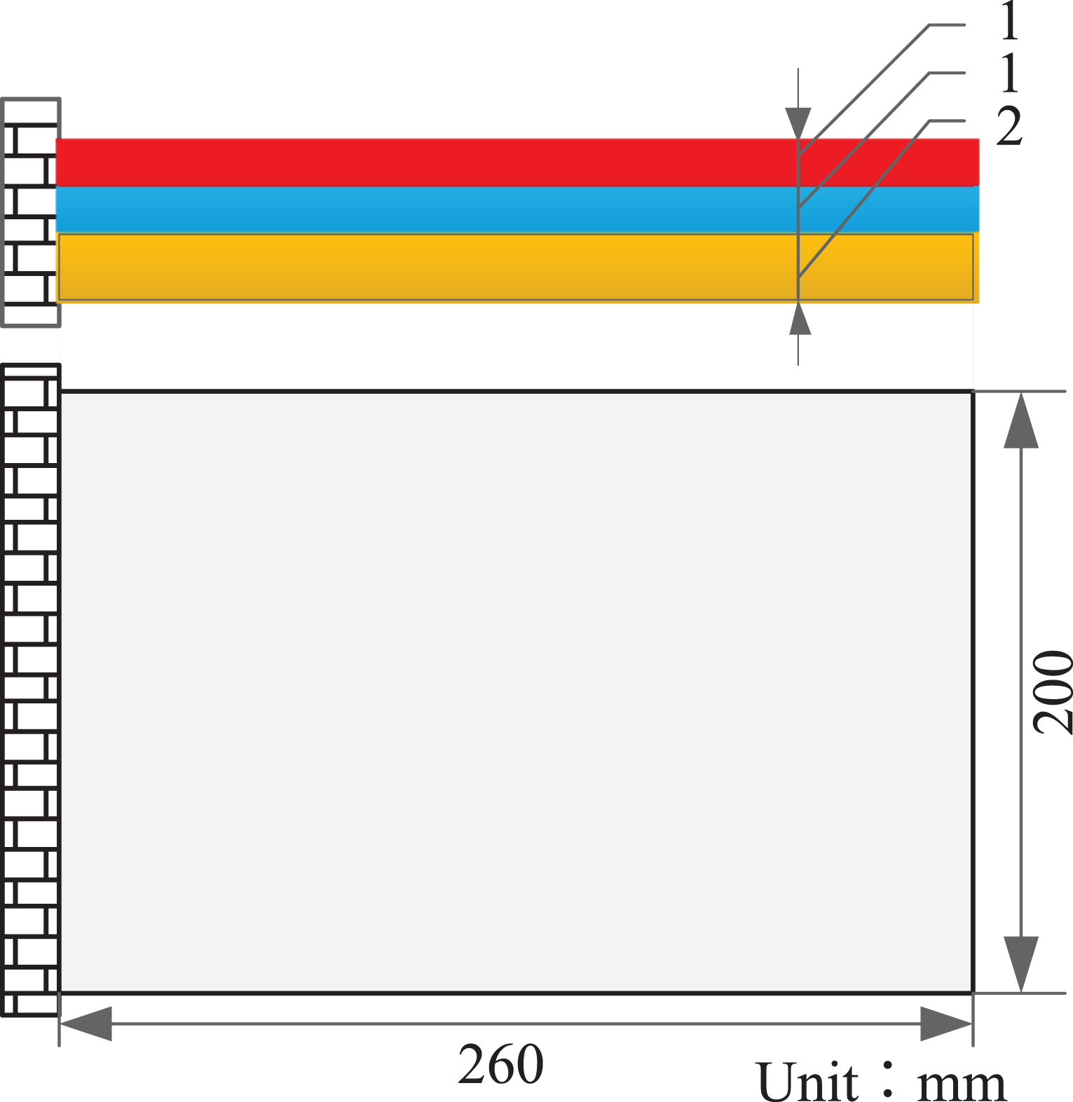
Cantilever constrained damping layer structure.
The test data of butyl rubber ZN-3 material.

Material parameters of constrained damper plate.
To ensure the accuracy of the test, the test system for the inherent characteristics and modal loss factor of the constrained damping plate is built. The composition of the test system is shown in Figures 3 and 4. The test system consists of (1) force hammer PCB8206-002 mode force hammer, (2) portable acquisition front-end BK 3050-a-060, (3) three-phase acceleration sensor BK 4524b-xyz, and (4) notebook MTC hammer test software.

Test system of constrained damping structure.

Test system of real constrained damping thin plate structure.
In the test system, the force hammer is used to excite the frequency of the constrained damping thin plate. In the process of striking, the vertical direction of striking should be kept, and the force should be moderate to ensure that each exciting force is pure without clutter and secondary rebound signal. The portable acquisition front-end BK is used to record each response signal. The MTC hammer test software in the notebook is used to control the test system and save the test data
For the constrained damping layer structure of the test sample, the clamping end with a distance of 28 mm is reserved, and there are four holes with a diameter of 13.5 mm and there are four M12 bolts at the clamping end, as shown in Figure 5. In addition, torque wrench is used to tighten the bolt with a tightening force of 34 N/m. Its purpose is to simulate the constraint condition of cantilever, reduce the error caused by the test, and ensure the accuracy of the test.
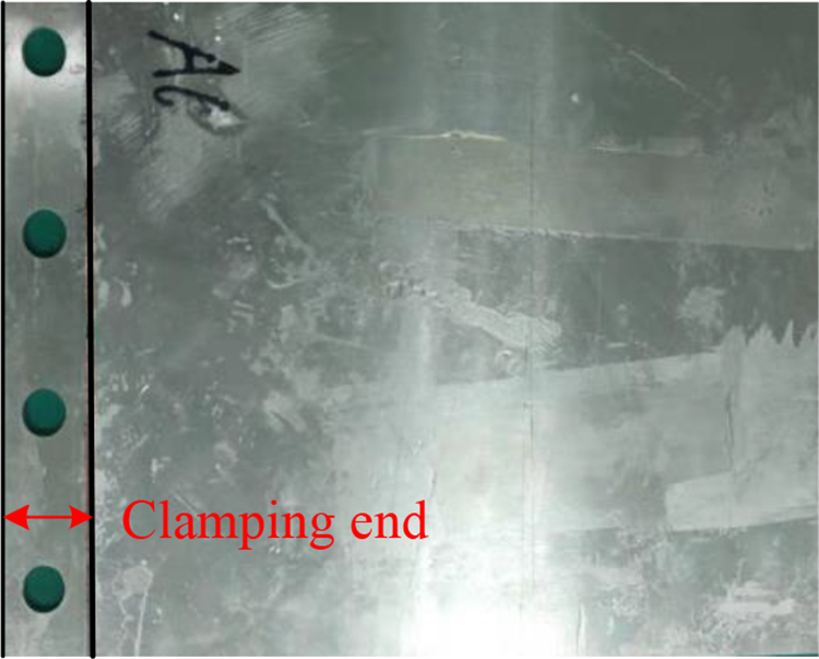
est specimen.
According to the two solutions of complex eigenvalue and modal strain energy proposed in the first two sections, the first three natural frequencies and modal loss factors of the structure are calculated and compared with the test data measured by the above test system, as presented in Table 3.
Comparison of theoretical and experimental test data.
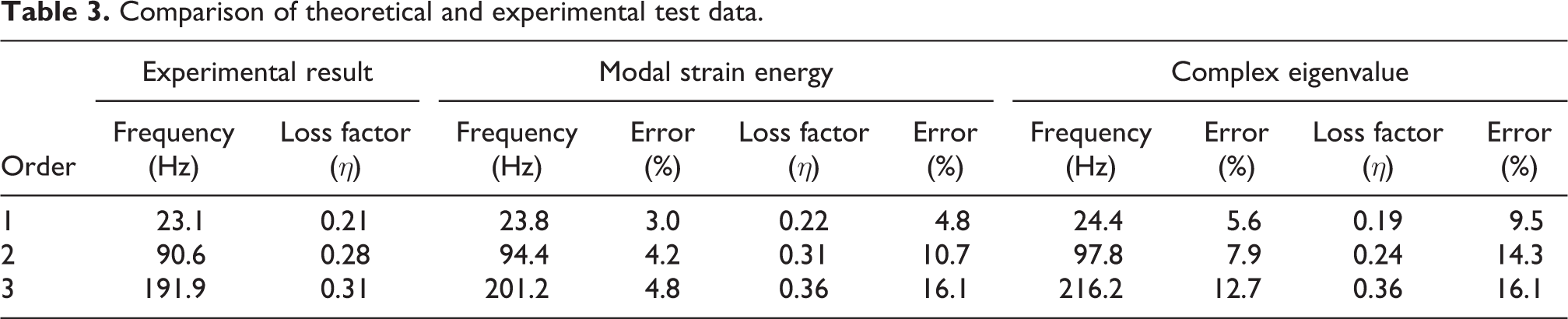
The first three natural frequencies and modal loss factors of the model calculated by the two methods in this article are compared with the test values. It can be seen from Table 3 that compared with the complex eigenvalue method, the natural frequencies calculated by the modal strain energy method are slightly smaller. This is because the virtual part of the complex stiffness matrix is ignored in the calculation process of the modal strain energy method. When calculating the loss factors, the modal strain energy method is slightly larger than the complex eigenvalue method. Compared with the test data, the prediction of modal strain energy method is more close. We can see that the prediction error of modal loss factor is a little larger because the damping material has temperature frequency characteristics; in the real test process, the room temperature does not reach the ideal temperature of 25°C, which will cause the test modal loss factor to be smaller. In conclusion, compared with the complex eigenvalue method, the modal strain energy method can reduce the design variables and greatly shorten the calculation time.
Study on the damping mechanism of constrained damping layer
Viscoelastic damping material has good damping performance. In the design of vibration reduction, it is attached to the mechanical structure to be treated with vibration reduction and noise reduction, and constrained damping treatment is an effective means of passive vibration control. The mechanical property parameters, position, and area of the viscoelastic constraint layer will affect the damping performance. Taking the above calculation example, this chapter analyzes the influence of the modulus, material thickness, location, and area of the constrained layer damping on the loss factor of the structure.
Analysis of the influence of energy storage modulus and loss modulus of damping materials on the vibration characteristics of structures
Assuming that the other parameters of the constrained damping structure remain unchanged, the effect of the storage modulus of the damping material on loss factor of constrained damping structure is studied. The storage modulus changes from 1 MPa to 10 MPa. The influence of loss factor of constrained damping structure with the change of storage modulus of damping material is shown in Figure 6.

Change curve of modal loss factor with damping layer storage modulus.
It can be seen from Figure 6 that the storage modulus of viscoelastic damping material has little effect on the loss factor of constrained damping structure, because the storage modulus of viscoelastic material is small compared with the base layer, and has little effect on the modal loss factor of the whole structure.
Similarly, taking the loss modulus of damping material as a variable, the influence of the loss modulus of damping material on the loss factor of constrained damping structure is studied. The loss modulus changes from 1 MPa to 10 MPa. The influence of the loss factor of the constrained damping structure on the loss modulus of the damping material is shown in Figure 7.

Change curve of modal loss factor with damping layer loss modulus.
It can be seen from Figure 7 that with the increase in the loss modulus of viscoelastic damping material, the modal loss factor of constrained damping structure increases first and then decreases. This is because when the constrained damping structure is bent and deformed, the damping layer produces shear strain, which makes part of the mechanical energy loss. Therefore, to achieve good damping effect, the loss modulus of viscoelastic damping layer should be selected according to the actual situation.
Analysis of the influence of the elastic modulus of the constrained layer on the vibration characteristics of the structure
Based on the assumption that the other parameters of the constrained damping structure remain unchanged, the influence of the elastic modulus of the constrained layer material on the loss factor of the constrained damping structure is studied. The elastic modulus of constraint layer changes from 20 GPa to 80 GPa. The influence of the loss factor of the constrained damping structure on the elastic modulus of the constrained layer material is shown in Figure 8.
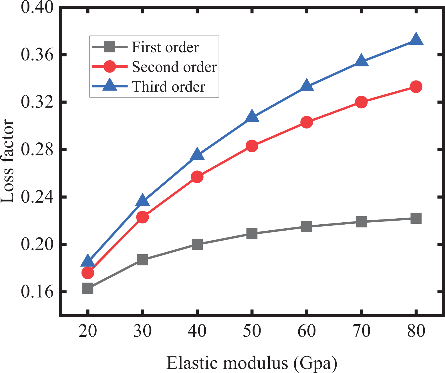
Change curve of modal loss factor with constrained layer elastic modulus.
It can be seen from Figure 8 that with the increase in the elastic modulus of the constrained layer material, the modal loss factor of the constrained damping structure begins to increase rapidly with the increase of the elastic modulus of the constrained layer material, and when it reaches a certain value, the increase decreases and tends to be stable. In engineering practice, aluminum is commonly used as metal material, with an elastic modulus of 7 × 10⁴ MPa, as a constraint layer material.
Analysis of the interaction between the thickness of damping layer and constraint layer
In the design of constrained damping structure, the larger the loss factor is, the more energy the constrained damping structure dissipates, which means the safer the structure. Therefore, in the damping design, the damping effect is mainly measured by the loss factor. The change of thickness of damping layer and constraint layer will affect the loss factor. In this section, the influence of the change of thickness of damping layer and constraint layer on the best thickness of another layer is calculated, respectively. The relationship between the loss factor of constraint damping structure and the thickness of damping layer and constraint layer is shown in Figure 9.

Curve of modal loss factor with the interaction between damping layer and constraint layer thickness, and which h represents damping layer thickness.
It can be seen from Figure 9 that with the increase in the thickness of the constrained layer, the first three modal loss factors of the constrained damping structure increases first and then decrease, and there is an extreme value. For the increase in the thickness of the damping layer, the modal loss factor is positively related to the increased thickness. In this article, the base course of constrained damping structure is 2 mm. From figures (a) to (c), it can be seen that the extreme value of constrained layer thickness is around 2 mm. For the optimal thickness, the ratio of constrained layer thickness and base course thickness is 1 mm. For the thickness of damping layer, the thickness of damping layer can be selected according to the actual vibration reduction requirements.
Analysis of the influence of the position of the constrained layer on the vibration characteristics of the structure
This article studies the influence of the sticking position of the constrained damping on the vibration characteristics of the structure. The viscoelastic constrained layer damping material is partially pasted along the length direction of the cantilever constrained damping structure. The schematic diagram of the partially pasted constrained damping structure is shown in Figure 10, where the size parameters of the constrained damping structure are consistent with the previous example, the length of the pasted constrained damping material is 0.08 m, and the center distance of the damping material is 0.08 m. The distance between clamping ends is a.
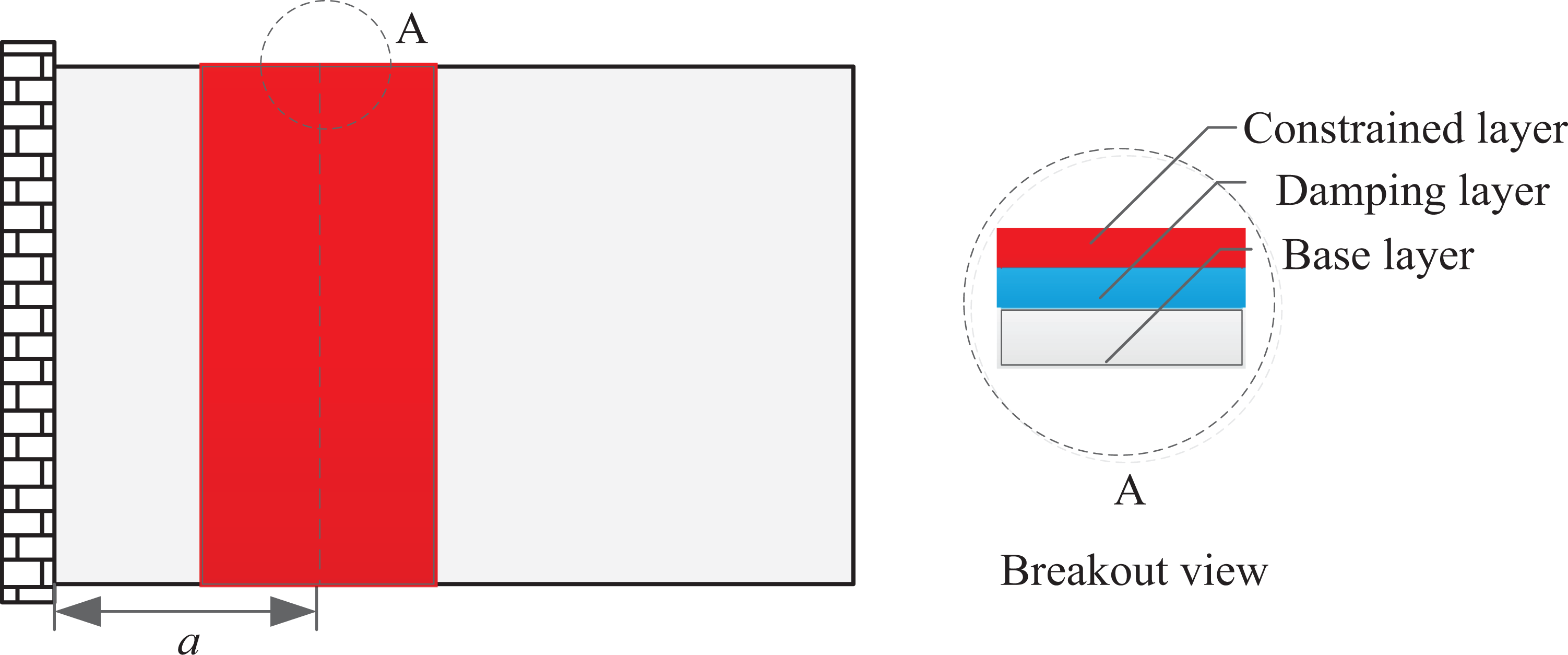
Damping diagram of local paste constraint laye
The distance between the center of damping material and the clamping end is 0.05 m, 0.1 mm, 0.15 m, and 0.2 m, respectively. The natural frequency and modal loss factor of the first three orders of constrained damping structure are calculated, respectively, and the relation curve is as shown in Figure 11.

Change diagram of modal loss factor of local sticking constraint layer.
It can be seen from Figure 11 that the first mode loss factor of constrained damping structure decreases with the increase of distance from the center of damping material to the clamping end as a; the change trend of the second mode loss factor and the third mode loss factor are roughly the same, both decrease with the increase of a and reach the peak value at a = 0.1 and a = 0.15, respectively. Then it gradually decreases.
Analysis of the influence of the position of the constrained layer on the vibration characteristics of the structure
Then, the influence of adhesive area of the constrained layer damping along the length direction of the sheet on the vibration characteristics of the whole structure is analyzed. The constrained layer damping material is pasted from the constrained end of the cantilever, and the adhesive length is y meter, as shown in Figure 12. Comparing the influence trend of natural frequency and loss factor of thin-walled constrained damping structure when the proportion of bonding area is 20%, 40%, 60%, 80%, and 100% respectively, assuming that the structural parameters are consistent with the analysis of the above subsection examples, the values of bonding length y are y = 0.052 m, y = 0.104 m, y = 0.156 m, y = 0.208 m, and y = 0.260 m, and the relationship curve is obtained, as shown in Figure 13.
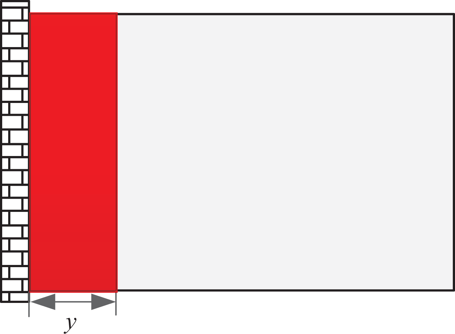
Sketch map of partial paste constraint layer.

Change diagram of modal loss factor of local sticking constraint layer.
It can be seen from Figure 13 that with the increase in the adhesive area of the constrained layer damping, the loss factors of the thin-walled constrained damping structure are gradually increasing, but the increasing speed and amplitude are different. Among them, the first order loss factor has a larger growth range, and the rest order loss factor has a smaller growth range. The larger the bonding area is, the larger the loss factor of the whole structure is, and the more obvious the vibration reduction effect is.
Calculation and analysis of vibration response of space science experiment cabinet
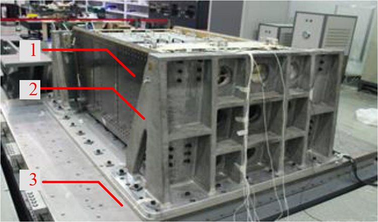
The space science experiment cabinet is mainly composed of main structure body 1, bearing structure (SPU) 2, electronics and thermal control drawer (SDU) 3, as shown in Figure 14. The space science experiment cabinet is launched with the rocket. Its input condition is the same as that of the rocket. In the vibration test, sinusoidal vibration is usually used as the input condition.

Structure of space science experiment cabinet.
Sinusoidal vibration input condition
Sinusoidal vibration test is the most commonly used method in spacecraft vibration test nowadays. Sweep frequency test can be carried out through sinusoidal excitation force generated by vibration test bench, which can control the overall time of test and avoid the damage of workpiece caused by too long test. The input conditions are presented in Table 4.
Input conditions of sinusoidal sweep.

Vibration response analysis of space science experiment cabinet
During the vibration test, because the test cabinet cannot be directly connected with the vibration test bench, it needs tooling to realize the fixed constraint between the test cabinet and the vibration test bench. In the simulation analysis, the tooling should also be considered. The MSC Nastran software is used to analyze the vibration of the space science experiment cabinet in three directions of x, y, and z. The displacement simulation analysis results under the resonance frequency are shown in Figure 15.

Analysis of vibration response in x direction (a), y direction (b), and z direction (c).
From Figure 15, we can see that the maximum displacement of the scientific experiment cabinet in x, y, and z directions is 1.73, 3.82, and 2.1 mm, respectively, while for the vibration response of the bottom drawer position, the vibration displacement response in y direction is the largest. To further obtain the vibration acceleration response of the drawer mounting frame structure, the acceleration response cloud diagram of the frame structure under the resonance frequency is extracted, as shown in Figure 16. It can be seen from the figure that the resonance peak value is 84 Hz and the maximum acceleration response is 40 g.

Vibration acceleration of drawer mounting frame.
Vibration response analysis of experimental cabinet with additional constrained damping layer
The viscoelastic restraint damping layer is laid on the four carbon fiber plates on the upper and lower sides of the drawer mounting frame shown in Figure 16 to suppress the vibration input of the drawer mounting interface. Among them, the damping layer is modeled by 3D solid element, and the constraint layer and base layer are modeled by 2D plate element. The Hypermesh software is used for mesh generation and attribute assignment. The final finite element model of the constraint damping layer is shown in Figure 17.

Vibration acceleration of drawer mounting frame.
According to the above analysis results, it is known that the focus is on the y-direction vibration acceleration response of the drawer mounting frame structure, and the response cloud diagram is shown in Figure 18. After the viscoelastic constrained damping structure is laid, the maximum acceleration response of the drawer mounting frame is 17.51 g, and its resonance frequency is 88 Hz.

Acceleration response of drawer installation frame with constrained damping layer.
Through the comparison of simulation results, it is found that the resonance acceleration response amplitude at the bottom drawer mounting interface is reduced from 40 g to 17.51 g, and the vibration suppression effect is obvious.
Experimental study on vibration suppression of space science experiment cabinet
As shown in Figure 19, 1 is the space science experiment cabinet, 2 is the tooling (the experiment cabinet cannot be directly connected with the vibration table), 3 is the vibration table, the test system adopts Siemens manufacturer's LMS test software, the sensor is the acceleration sensor, and the model is 4524b. According to the above simulation analysis, only y-direction vibration test is required, and the input conditions are the same as Table 3.
Vibration test of space science test cabinet.
Because of the compact structure of the space science experiment cabinet, it cannot provide enough installation space and mass to reduce the vibration by arranging dampers and other methods. Therefore, it is a desirable measure to add damping layer v and constraint layer c to the original substrate s (aluminum plate) to form a constraint damping structure for vibration reduction.
As shown in Figure 20, the base course is made of 7075 aluminum alloy with a thickness of 2 mm; the damping layer is made of butyl rubber with a thickness of 1 mm; the restraint layer is made of 7075 aluminum alloy with a thickness of 1 mm. The material parameters are listed in Table 5.
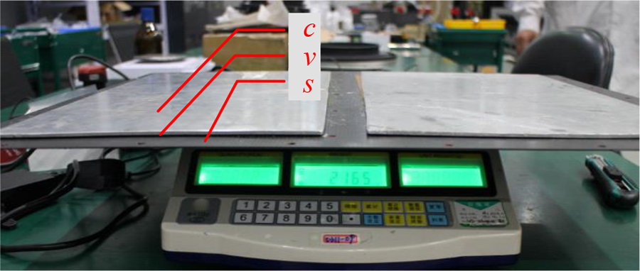
Real specimen of constrained damping layer.
Material parameters of constrained damper plate.

Vibration response analysis and comparison
The y-direction vibration experiments are carried out on the test cabinet without additional constrained damping layer and the test cabinet with additional constrained damping layer, respectively. The comparison results of acceleration response are shown in Figure 21.

Vibration test of space science test cabinet.
It can be seen from Figure 21 that the resonance peak value of the space science experiment cabinet with additional constrained damping plate is 86 Hz, and the acceleration response is reduced from 42.5 g to 18.6 g, with a reduction of 56.25%. The viscoelastic constrained damping layer can reduce the vibration of the drawer at the bottom of the space science experimental cabinet significantly without significantly increasing the mass.
Conclusion
The results show that the acceleration response of the space science experiment cabinet exceeds the standard under the first resonance frequency. To reduce the magnitude of vibration, the method of adding additional constrained damping layer is used to optimize the vibration suppression of space science experiment cabinet. The space science experiment cabinet with additional constrained damping layer is verified by simulation and experiment, and the following conclusions are obtained: For the analysis of the dynamic model of the constrained damping layer, the effect of the real elastic modulus of the damping material on the structural system can be ignored. Based on the modal strain energy method, the natural frequency of the structural system can be solved with high accuracy and the calculation time can be greatly reduced. For a specific constrained damping structure, there is an optimal material mechanical parameters to maximize the modal loss factor. The modal loss factor increases first and then decreases with the loss modulus of damping layer and tends to be stable with the increase of elastic modulus of constraint layer. In addition, the relationship between the thickness of the damping layer and the thickness of the constraint layer is explored. The modal loss factor increases with the increase in the thickness of the damping layer. When the ratio of the thickness of the constraint layer to the thickness of the base layer is close to 1, the modal loss factor is the largest, and the local sticking of the damping material can also ensure that the constrained damping structure has a higher modal loss factor. The first-order resonance frequency of the space science experiment cabinet without additional constrained damping layer is 84 Hz, the acceleration response is 40 g, and the maximum vibration displacement response occurs at the bottom drawer position. The application of viscoelastic constrained damping layer in the space science experiment cabinet has obvious vibration suppression effect, focusing on the reduction of acceleration response of drawer position by more than 56%, achieving the expected vibration suppression effect, providing an important guarantee for the reliable operation of space science experiment.
Footnotes
Declaration of conflicting interests
The author(s) declared no potential conflicts of interest with respect to the research, authorship, and/or publication of this article.
Funding
The author(s) disclosed receipt of the following financial support for the research, authorship, and/or publication of this article: This research was financially supported by National Natural Science Foundation of China (No.51975567 and No.51505470); Liao Ning Revitalization Talents Program (XLYC1907152); Natural Science Foundation of Liaoning Province (2019-MS-347); State Key Laboratory of Robotics (Y7C1207); Youth Innovation Promotion Association, CAS (No.2018237); and Jiang Xin-song Innovation Fund (No.20180504).