
Abstract
The present study investigates the performance of U-type clamp anchorage on external strengthening of reinforced concrete beams using carbon fibre-reinforced polymer composites. Unidirectional carbon fibre was used to strengthen the beam having a cross-section of 150 × 200 mm2 and the fabricated U-type clamp was used as a clamping device to enhance the fibre-reinforced polymer (FRP) bonding. To test the beam, four-point bending system was adopted and the experimental parameters were the number of FRP layers. The failure mode of strengthened beams with U-type clamp was very similar (rupture of FRP composites) to the beams without U-type clamp. However, the delamination of FRP was evaded by counteracting the peeling stress development at the edge of fibre. Since the beams strengthened with U-type clamp exhibited more linear behaviour than that of the beams strengthened without U-type clamp, there may be a higher possibility for abrupt/rapid/brittle mode of failure and the ductility index of the beam with U-type clamp confirmed the above behaviour. However, the introduction of U-type clamp enhanced the flexural stiffness and ultimate strength by counteracting the debonding, and the beam with U-type clamp exhibited a maximum of 58.33% and 20.37% enhancement in flexural stiffness and ultimate strength than that of the beam without U-type clamp, respectively. The theoretical strength value of all strengthened beams was evaluated using models proposed in the previous research and compared with experimental results. It is inferred that the use of U-type clamp in FRP strengthening provides economic and structural benefits compared to a beam without U-type clamp.
Introduction
In the present era, the external strengthening reinforced concrete (RC) beams using fibre-reinforced polymers (FRPs) become an effective method and the reason may be due to their high stiffness, high strength-to-weight ratio and easy installation process. In addition to that FRPs are having a very stable geometry during the period of service. Over the last few decades, wide range of experimental and analytical research studies have been conducted on the structural behaviour of RC beams externally retrofitted by FRP composites and the research studies mainly related to the bonding of FRP composites to the bottom/tension zone of the RC beams and the research parameters were the type of FRP, an increase in thickness and the width of FRP layers. 1 –10 The research outcomes of studies performed by Saadatmanesh and Ehsani, 11 Ritchie et al., 12 Chajes et al., 13 and Swamy and Roberts 14 confirmed that the bond strength at the interface between FRP and concrete determines the effectiveness of the FRP-strengthened RC beams and it has been suggested that suitable anchorage method in FRP external strengthening, to avoid the debonding of FRP composites FRP strengthening. 6 –8,13,15,16
Uomoto et al. 16 recognized that the peeling stress development at the end of FRP composite limits the strength capacity enhancement of the beam. In addition, 69% of the FRP-bonded RC beams failed through debonding/separation of the FRP composites. To resolve these issues, researchers recommended/suggested the use of mechanical fasteners or clamps at the end of FRP composites to enhance the bonding strength of FRP composites. Lamanna et al., 17 Lamanna, 18 and Lamanna et al. 19 performed a series of tests on 304 × 304 × 3657 mm3 concrete beams externally strengthened by mechanically fastened carbon fibre-reinforced polymer (CFRP) composite. The test results revealed that the beam strengthened with mechanically attached FRP composites exhibited 21.60% and 20.10% enhancement in yield moment and ultimate moment, respectively, than the control beams. The findings of Tang and Saha 20 have shown that the FRP strengthening along with mechanical fasteners significantly enhanced the flexural strength capacity of the RC beams. Based on the experimental and numerical results, Napoli 21 critically analysed the interfacial behaviour between the mechanically fastened FRP (MF-FRP) laminate and concrete. From the analysis, it has been inferred that the external FRP strengthening of RC members using different fastener layouts may offer promising results. Yingwu Zhou et al. 22 performed an experimental investigation to understand the effect of the positive pressure exerted by the hybrid anchorage device on the bond behaviour of the CFRP-to-concrete interface. Eighteen square concrete specimens with a size and length of 150 mm and 1200 mm, respectively, was prepared, and the specimens were strengthened by low-modulus unidirectional CFRP. From the test results it was found that the debonding stress of the FRP composite can be controlled by regulating the torque provided to the fastener, and the alteration in torque improved the FRP utilization rate from 36.1% to 91.7%. Yingwu Zhou et al. 23 investigated the performance of H-type end anchorage on the flexural performance of RC beams externally strengthened by low-modulus FRP plate. A total of five rectangular beam specimens were prepared to perform four-point bending test, and the size of the beams was 150 mm wide, 250 mm deep and 2400 mm long. The test results of beams revealed that the H-type end anchorage significantly improved the critical load and the ductility of the concrete beams to the maximum of 20.47% and 203%, respectively. Fabio Nardone et al. 24 proposed the analytical model to predict the flexural behaviour of RC members strengthened using MF-FRP strips, both at serviceability and ultimate limit states. Equilibrium, compatibility and constitutive relationships of the constituent materials; in particular, it accounts explicitly for the slip between the substrate surface and the FRP strip due to the behaviour of the fasteners have been taken in to account to establish the model.
From the detailed literature, it can be understood that the MF-FRP strengthening method is a virtuous method to strengthen the RC beam, and it has a numerous advantages over traditional FRP strengthening method. Generally, the mechanical fasteners were pinned or bolted in to the concrete substrate, developing further friction between the concrete and the FRP. Though the above-mentioned anchorages improved the strength capacity of the beam, low improvement in ductility and ultimate deformation was observed. To address these issues, a new end anchorage (U-type clamp) was evolved to improve the strength, deformation capacity and the ductility of the RC beams strengthening. The U-clamp anchorage system placed at a termination of FRP laminates delays the crack opening at the onset of debonding and evades the plate-end interfacial debonding or concrete cover separation. Dat Duthinh and Monica Starnes 25 investigated the effectiveness of steel clamp in enhancing the anchorage between the FRP laminates and concrete. The steel plate having a width of 203 mm was used as a clamp and two double-ended threads were used to link the grip and FRP anchorage. Clamps were torqued to 400 N·m and the applied compressive forces ranged between 15 kN and 25 kN. The test results revealed that the anchorage of CFRP laminates at the end evaded the debonding of laminates and improved the beam strength. Tomas Skuturna and Juozas Valivonis 26 utilized steel clamp to enhance the bonding properties between the FRP and concrete. Further, they have examined the influence of steel clamp area on the bonding properties of CFRP. The CFRP composites were anchored by steel clamps having a width of 50, 100, and 15 mm. Two or four bolts (double threaded) were used to link the top (grip) and bottom (anchorage clamp) steel clamps. Steel clamps were adjusted with different torques to induce different initial compressions on the CFRP composites. It was found that the introduction of steel clamp at the edge of the beam improved the ultimate moment of the strengthened beams. Furthermore, the increase in the compression area of the steel clamp enhanced the stiffness of the bond between the concrete and the CFRP composites.
In this present study, the end anchorage was fabricated using low-carbon soft steel, and the CFRP was used to strengthen the RC beam (Figure 1). Epoxy-based resin was used to achieve the FRP bonding. The beams were externally bonded by CFRP with one, two and three layers, and for each series three specimens were tested. Four-point bending was applied to test the beam. To examine the effectiveness of U-type clamping as a mechanical fastener in FRP strengthening method, the beams were tested to failure and the observation includes failure modes, load and corresponding deflection and ultimate/failure load. The design model proposed to predict the strength capacity of FRP-strengthened RC beams by Ilker Fatih Kara and Ashraf F Ashour 27 and Lawrence C Bank and Dushyant Arora 28 was considered in this study to determine the theoretical strength.

(a) Proposed U-clamp anchorage. (b) Proposed U-clamp for existing structure applications.
Experimental investigation
Material properties and concrete
Ordinary Portland cement available in the local market was used as a binding material in this study. The specific gravity of the cement was tested (IS 8112: 2013 29 ) and the obtained value was about 3.12 g/cm3. Natural river sand passing through 4.75 mm was used as fine aggregate, and crushed basalt stone about 20 mm size was used as a coarse aggregate. According to the procedure recommended in IS 2386(1):1963, 30 sieve analysis was performed for both fine and coarse aggregates and the obtained values were 2.51 g/cm3 and 2.66 g/cm3, respectively. Steel bar with the nominal yield strength of 415 MPa was used in this study as reinforcement. Two 10 mm bars and two 8 mm bars were used as a bottom and top reinforcement, respectively. Bar with 6 mm diameter was used as a rings/stirrups, and the effective spacing between the stirrups was about 100 mm. The beam reinforcement details are shown in Figure 2. Sikawrap-230C 31 (SIKA India Inc., Mumbai, Maharashtra, India) was used as external FRP reinforcement to strengthen the RC beams. It is a unidirectional carbon fibre having a stiffness and tensile strengths of 230 GPa and 4300 MPa, respectively. It is a fabric type having a thickness of 0.131 mm. The resin recommended by the manufacturer named Sikadur-330 (SIKA India Inc., Mumbai, Maharashtra, India) was used as a bonding agent to make a bond between the CFRP and concrete. It is a binary system of resin having resin and hardener, and the resin and hardener mix ratio was 1:4 (hardener:resin). A concrete mix with the compressive strength of 25 MPa (M25) was used to fabricate the beam specimens, and the mix proportion was obtained according to the procedure described in IS 10262:2009. 32 Three cube specimens were tested at the age of 28 days to determine the strength capacity of the concrete, and the obtained average cube compressive strength was 37.5 MPa.

Beam reinforcement details.
Beam fabrication, FRP wrapping and mechanical fastening
A total of 21 RC beams with the cross-sectional dimension and length of 150 × 200 mm2 and 2000 mm, respectively, were fabricated. The design moment capacity of the RC beam is 13 kN·m. Of the 18 beams excluding the 3 reference beams, 9 beams were externally strengthened by CFRP composites with one, two and three layers and the remaining 9 beams were externally strengthened by CFRP composites (one, two and three layers) with U-clamp as a mechanical fastener. For concrete mixtures, the aggregates include cement, sand and coarse aggregates were weighed and mixed homogenously in concrete mixer for 3 min. With the required cover specified in IS 456-2000, the reinforcement was placed in the mould and the mould was filled with concrete layer by layer, and each layer of concrete was effectively compacted by the needle vibrator to ensure the concrete was free from air gaps and flaws. The moulds were removed after 24 h, and the beams were allowed to curing. During fabrication of beams, the cube specimens were fabricated and they were tested at the age of 28 days to determine the strength of the concrete, and the obtained average cube compressive strength was 37.5 MPa. At the age of 29 days, all the beams were externally bonded with CFRP composites with three different layers. To achieve an effective bond between the concrete and FRP composites, the soffit of the beam was roughened by sand blasting using coarse sand. After that all the beams were covered with polythene sheet and kept in an airtight room. Prior to applying CFRP composites, the sand blasted surface was cleaned using air blower to remove any dust present on the beam, followed by FRP composites were attached to the beams with three different layers. 33 During bonding, to remove the excessive resin in the CFRP, steel roller was used to squeeze the excessive resin. The thickness of the resin-coated FRP was varied between 0.54 mm and 0.61 mm. The variation in thickness of the CFRP across the entire specimen was 0.05 mm. After strengthening, all the beams were allowed to curing for 10 days under room temperature 28°C. 33
The steel section having a width and thickness of 30 mm and 15 mm, respectively, was used as a grip and FRP anchorage, and they were placed at the top and bottom of the concrete beams, respectively. The grip and FRP anchorages were linked through double-ended threaded bolts, and the anchorage to the FRP was achieved by tightening the double-ended threaded nuts. Torque wrench was used to apply torque on the bolts of the anchor, and the constant torque level of 6 N·m was applied to all the beams. Commonly, the U-clamp anchorage can be effectively used at the termination of FRP laminates, and sometimes throughout their entire length. In the present study, the U-clamp anchorage system placed at a distance of 750 mm from the mid-span of the beam to evade the plate-end interfacial debonding or concrete cover separation.
With respect to the real applications, the grip anchorage section can be achieved by tightly fixing the spring anchors in side face of the beam (above the neutral axis) at a required interval. After that the FRP clamp/anchorage section (steel section with a minimum width and thickness of 30 mm and 10 mm, respectively) can be linked to the grip anchorage through double-ended threaded bolts, and the anchorage to the FRP can be achieved by tightening the double-ended threaded bolts, thus evade the FRP slip at this section.
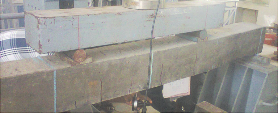
Test setup
All the beams were tested immediately after resin curing, and the approximate age of the beam at the time of testing was 40 days. Four-point bending system was used to test the beams, and they were tested in the loading frame with the capacity of 1000 kN. The load was applied manually using 100 ton hydraulic jack, and the load was continuously increased up to failure. Linear variable displacement transducers (LVDTs) with the accuracy of 0.01 mm were used to measure the deflection of the beam at three points (mid-span and loading points), and the 100 ton load cell was used to monitor the load. Both LVDTs and load cell were connected to the data acquisition system to store the respective data. All the beam specimens were tested up to failure, and the experimental observation includes the mode of failure and crack pattern, deflection corresponding to the applied load and ultimate load.
Specimen description
Since three beams were tested for each series, beams were designated with names to identify the specimens easily. The names are Con.Beam (1), Con.Beam (2), Con.Beam (3), CFRP-1(1), CFRP-1(2), CFRP-1(3), CFRP-2(1), CFRP-2(2), CFRP-2(3), CFRP-3(1), CFRP-3(2), CFRP-3(3), CFRP-MF-1(1), CFRP- MF-1(2), CFRP- MF-1(3), CFRP- MF-2(1), CFRP- MF-2(2), CFRP- MF-2(3), CFRP- MF-3(1), CFRP- MF-3(2) and CFRP- MF-3(3). The specimen CFRP-1(1) and CFRP-MF-1(1) specifies the RC beam strengthened by one layer of CFRP composites without and with mechanical fasteners, respectively. The beam Con.Beam (1) specifies the control beam. The number in the bracket specifies the number of specimen in the each case.
Results and discussion
Failure modes
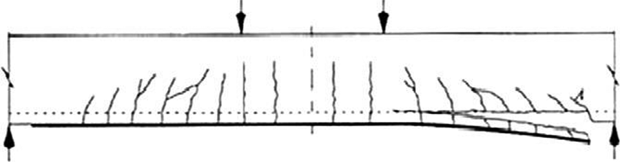
The beam specimens were positioned at the supports to ensure the symmetric loading, and all the specimens were tested to failure to understand the influence of CFRP bonding on the structural behaviour of RC beams. In the control/reference specimens, first crack was observed at approximately 27 kN (which is equal to 61% of the failure load of the beam) around the mid-span of the beam, and few other cracks were observed around the loading points upon the increase in load. With respect to the increase in the load, in all the beams, the cracks propagation started from soffit to towards centre/neutral axis of the beam, and the crack width of all the beams has been increased with the increase in load. At the final stage, all beams were failed by flexural failure mode which is shown Figure 3. The failure mode and the ultimate load of all the beams were summarized in Table 1. At the stage of failure load, the deflection of all the beams was between 11.54 mm and 12.15 mm, which shows that the un-strengthened beams are having more ductile nature.
Failure pattern of control beam.
Test results.

CFRP: carbon fibre-reinforced polymer; FRP: fibre-reinforced polymer; MF: mechanically fastened.
During the initial stage, all the strengthened beams with one and two layers behaved very similar to the reference beam, and the steel reinforcement located in the bottom of the beam resists the major load rather than the CFRP bonded in the bottom of the beam. Since the beams started to experience the tensile load with the increase in the load, the tensile force transferred to the CFRP system and the CFRP system resists the major load. Thus, load sharing/transferring enhanced the moment carrying capacity/flexural strength capacity of the beam. Once the CFRP system started to experience the tensile stresses, the shear stress tends to flow on to the horizontal reinforcement along the length of the beam, causing failure of the weak cover concrete led to the rupture of the FRPs with concrete (FRP-concrete rip-off to failure) which is shown in Figures 4 and 5. Figure 6 shows the failure mechanism of crack initiation and rupture of fibres. 15 In the case of beam bonded with three layers, the behaviour of the beams was very similar to the beam bonded with one and two layers. Nevertheless, debonding of fibres was triggered once the rupture started, and the failure pattern is shown in Figure 7.

Failure pattern of beam bonded with one layer (classical method).

Failure pattern of beam bonded with two layers (classical method).
Failure mechanism of crack initiation. 15

Failure pattern of beam bonded with three layers (classical method).
The failure of beams strengthened by CFRP with mechanical fastening (U-type clamp) was very similar to the beams bonded with CFRP composites without mechanical fasteners. However, the delamination of the CFRP composite from the substrate was evaded with the application of U-type clamp, in addition to that the introduction of U-type clamp shifted the rupture of fibres to the mid-span and the near to the loading points. The failure pattern of beams with mechanical fasteners is shown in Figures 8 to 10. In addition to that, the introduction of U-type clamp enhanced the ultimate strength capacity of the beam. It is believed that the provision of U-type clamp evaded the initiation of peeling stress at the edge of fibre, thus enhanced the bonding of the CFRP composites. The delay in the debonding enhanced the strength capacity of the beam.

Failure pattern of beam strengthened by one layer with mechanical fastener.

Failure pattern of beam strengthened by two layers with mechanical fastener.

Failure pattern of beam strengthened by three layers with mechanical fastener.
Load–deflection behaviour
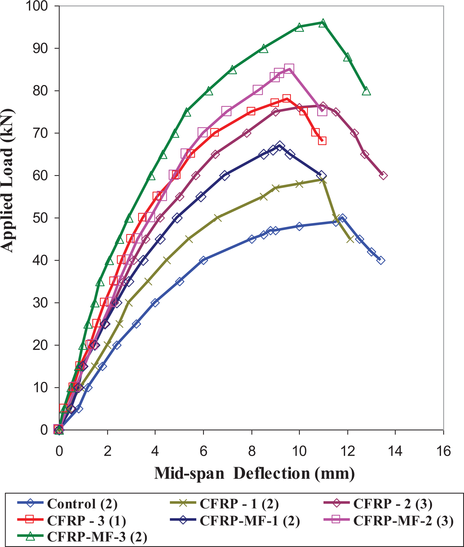
The load–deflection behaviour of beams strengthened by CFRP composite with and without U-type clamp is illustrated in Figure 11, and the deflection corresponding to the failure load is summarized in Table 1. Figure 11 illustrated that the external bonding of CFRP significantly enhanced the restraint against the deflection and also the strengthened beams exhibited more stiffness than that of the reference beam. In the case of beam strengthened in conventional method (without U-type clamp), the mid-span deflection at the failure load of beam series CFRP-1(2), CFRP-2(3) and CFRP-3(1) were 10.86 mm, 10.02 mm and 9.42 mm, respectively. At the respective failure load of reference beam, the deflection beam series CFRP-1, CFRP-2 and CFRP-3 were 4.3 mm, 4.3 mm and 3.5 mm, respectively, which were 64.18%, 155.81% and 214.29% lower than that of reference beam. The above difference in flexural stiffness attributed to the presence of CFRP layers. From Figure 11, it can be evident that the increase in the number of layers enhanced the flexural stiffness further. However, the enhancement was not linear which can be evident from Figure 12 and the similar observation was documented in Ganesh Prabhu et al. 33 At the respective failure load of beam series CFRP-1 and CFRP-2, the beam CFRP-3 achieved a deflection of 4.9 mm and 8.01 mm, respectively, which are 73.41% and 37.51% lower than that of CFRP-1 and CFRP-2, respectively. The increase in the number of layers enhanced the tensile force exerted by the FRP. Hence, the increase in the flexural stiffness occurred with the increase in number of layers. From Figure 11, it can be understood that the load–deflection behaviour of the beam strengthened with U-type clamp is very similar to the beam strengthened without mechanical fasteners. However, the beams strengthened with U-type clamp exhibited more linear behaviour than that of the beams strengthened without mechanical U-type clamp and it can be evident from Figure 11. It can be inferred that there may be a higher possible for abrupt/rapid/brittle mode of failure and it can be considered as a shortcoming of this system. However, the flexural stiffness of the beams strengthened with U-type clamp was significantly higher than that of the beams strengthened without U-type clamp. The control beam achieved a deflection of 11 mm at the ultimate load, whereas the beam series CFRP-MF-1(2), CFRP-MF-2(3) and CFRP-MF-3(2) achieved a deflection of 5.41 mm, 4.01 mm and 2.81 mm, respectively, at the respective failure load control beam, which are 103.71%, 175.01% and 292.86% lower than that of the control beam. In comparison with beam without U-type clamp, the beam with U-type clamp exhibited more flexural stiffness, especially the beam series CFRP-MF-2(3) and CFRP-MF-3(2) showed 28.57% and 58.33% higher flexural stiffness than that of CFRP-2(3) and CFRP-3(1), respectively. This is a result of the fact that the U-type clamp lie in the end of the beam, improved the bond between the concrete and CFRP and as a result the substantial load transfer was occurred.
Load–deflection behaviour of all beams—comparison.

Non-linearity in axial deformation control enhancement—comparison.
Ductility index
Ganesh Prabhu et al. 33 documented that the displacement ductility index of the FRP-strengthened beams is an important structural property due to their rupture and catastrophic failure mode. Based on the unique yield plateau of the stress–strain curve of steel rod, the load-carrying behaviour of the structural member can be forecasted while undergoing large deformations. But the load–deflection behaviour of the FRP retrofitted RC beam depends on many factors such as strength and stiffness, the ratio of internal reinforcements to the balanced steel, the ratio of internal to external reinforcements and the effectiveness of the external reinforcements. Since it is very difficult to establish unified definition of ductility considering the above factors, the author chosen mid-span deflection to define the ductility. Equation (1) recommended/documented in Ganesh Prabhu et al. 33 was used in this study to determine the ductility index of all the beams

where

Ductility indexes of all beams—comparison.
Flexural strength
The flexural strength capacity and the enhancement in the flexural strength capacity of the strengthened beams with respect to the reference beam are summarized in Table 1 and also presented in Figure 14. It was observed that the external bonding of CFRP composites enhanced the flexural strength capacity of the beam; in addition, the enhancement in flexural strength capacity of beam provided with U-type clamp was significant. In the case of classical strengthening method, in comparison with the reference beam, the beam strengthened with one and two layers of CFRP enhanced its flexural strength by 19.64% and 52.07%, respectively; however, the enhancement was not very high. But the beam series CFRP-3(1) enhanced its strength by 61.54% than that of reference beam. This is a result of the fact that the increase in the number of layers considerably enhanced the tensile strength during bending and as a result the flexural strength of the beam was increased with the increase in number of layers. However, the increase in the flexural strength is not linear with the increase in the number of layers, which can be evident from Figure 15. It was observed that the beam series CFRP-MF-2(3) and CFRP-MF-3(2) increased their flexural strength by 72.86%, and 94.45%, respectively, when compared to the control beam. Comparing the flexural strength of beam CFRP-MF-2(3) and CFRP-MF-3(2) to that of CFRP-2(3) and CFRP-3(1), beam CFRP-MF-2(3) and CFRP-MF-3(2) enhanced its flexural strength by 13.67% and 20.37%, respectively. The increase in the flexural strength with the introduction of fasteners may due to the fasteners lie in the end of the beam, increased the bond between the concrete and CFRP as a result the substantial load transfer was occurred. Another possible reason was decrease in the effective span of the CFRP composites. Because the introduction of mechanical fasteners at a distance of 750 mm from the mid-span of the beam, reduced the effective span of the CFRP as a result during bending tensile strength provide by the CFRP was increased.

Ultimate strength of all beams—comparison.

Non-linearity in axial ultimate strength enhancement—comparison.
Comparison of experimental and theoretical results
The numerical method followed by Ilker Fatih Kara and Ashraf F Ashour 27 and Lawrence C Bank and Dushyant Arora 28 was considered in this study to determine the theoretical results. The failure modes of strengthened beams and their dimensions were listed in Table 1. All the strengthened beam tested in this study was failed either by crushing of concrete followed by FRP rupture cum debonding or concrete crushing simultaneous with rupture of FRP composites and no debonding of CFRP. According to the method suggested by Ilker Fatih Kara and Ashraf F Ashour 27 and the method recommended in ACI 440.1R-06, 34 the balanced FRP reinforcement ratio (ρfb) was determined using equation (2)

where
If the FRP reinforcement ratio (ρf) is greater than the balanced FRP reinforcement ratio (ρfb) equation (3) was used to predict the moment carrying capacity (MFRP) of the strengthened beams

where

If in case the FRP reinforcement ratio (ρf) is lesser than the balanced FRP reinforcement ratio (ρfb), using equation (5) the moment carrying capacity (MFRP) of the strengthened beams was determined

where cb is the neutral axis for the balanced failure and defined equation (6)

where
To calculate the load-carrying capacity of the beam strengthened by FRP composites with mechanical fasteners, the empirical model suggested in Lawrence C Bank and Dushyant Arora 28 was adopted in this study. Seventy-five RC beams with different size and strengthened by MF-FRP was considered to propose the design model. Unidirectional carbon and glass fibres were used to strengthen the beams, and the expansion anchors were used to improve the FRP bonding. Assuming that the internal tension steel yields and the concrete fails in compression prior to the FRP strip failing or detaching, equation (7) was proposed to predict the nominal moment capacity of the RC beam strengthened with MF-FRP system. Since the failure mode of all the strengthened beams with mechanical fasteners were rupture of FRP composites, equation (7) was used to determine the strength capacity of the strengthened beams with mechanical fasteners

where As and Afrp are the area of the steel reinforcement and FRP composite, respectively; ds and dfrp is the centroid of the bottom steel and FRP from the top of the beam, respectively; a is the depth of Whitney stress block; fy is the yield strength of steel reinforcement. The depth of neutral axis can be determined from equation (8)

where

Once the neutral axis location determined, the strain

Experimental and theoretical strength comparison.
Conclusions
This present study investigated the effectiveness of U-clamps as a mechanical anchorage of external CFRP composites in RC beams strengthening. Though, the failure mode of strengthened beams with U-type clamp was very similar (rupture of FRP composites) to the beams without U-type clamp, the use of U-clamp anchorage at the end of CFRP composites has evaded the CFRP delamination by counteracting the peeling stress development at the edge of CFRP. The U-clamp anchorage reduced the beam deflection and improved the strength and stiffness of the beam. The external CFRP of the beam augmented with U-clamp enhanced the strength and flexural stiffness of the beam to the maximum of 94.45% and 292.86%, respectively. Though the anchorage of CFRP composites improved the bonding between CFRP and concrete, the brittle/rupture of the CFRP composites reduced the ductility performance of the strengthened beams. The use of clamps was found to be an effective technique to anchorage the FRP composites. The methodology to adopt this technique in real applications is also discussed. With respect to the real applications, spring anchors can be used to achieve a grip anchorage section, and the steel section with a width and thickness of 30 mm and 10 mm, respectively, can be used as a clamp/anchorage section. The double-ended threaded bolts can be used to link the grip and clamp anchorage section, and the minimum torque applied to the bolt of the anchor is 6 N·m. With respect to real application, the U-clamp anchorage system requires more fabrication works at site which includes drilling, bolting and fixing spring anchors using chemical compounds.
Footnotes
Declaration of conflicting interests
The author(s) declared no potential conflicts of interest with respect to the research, authorship, and/or publication of this article.
Funding
The author(s) received no financial support for the research, authorship, and/or publication of this article.