
Abstract
The phosphor bronze (PB) is widely preferred in various engineering applications due to its high strength, toughness, fine grain size, low coefficient of friction, and better corrosion resistance. The present work is to investigate the effect of tungsten disulfide (WS2) solid lubricant particle reinforcement in the phosphor bronze metal matrix composite (PBMC) through the mechanical and machining characteristics. The different variant of the composite is fabricated using stir casting technique by varying the volume percentage of WS2 particle from 0% to10%. The prepared PBMC samples are subjected to mechanical and machining (boring and high-speed turning) characterizations. The hardness (Brinell hardness) and flexural strength of the composites are examined as per the ASTM standard. The surface roughness (Ra) of the PBMC sample is analyzed through the boring and high-speed turning operations by varying the spindle speed, feed rate, and depth of cut. The scanning electron microscope (SEM) is employed to confirm the uniform dispersion of the reinforcement particle through the microstructural analysis. The presence of WS2 particles and other ingredients is ensured by X-ray diffraction analysis in the composites. The influence of WS2 reinforcement particles on tool life is analyzed on the PBMC4 (PBMC with 8% WS2) with the predefined machining parameters in the high-speed turning operation. The increase in WS2 particle (0–10%) improves the hardness (11.85%) and flexural strength in PBMC4 as compared to PBMC1 (PBMC with 0% WS2). At a higher spindle speed (1200 r/min), the Ra is reduced in PBMC1 as compared to 900 r/min, whereas the rest of the PBMC sample show higher surface irregularity at 1200 r/min.
Keywords
Introduction
The composites are fabricated by the addition of two or more dissimilar materials to enhance the explicit behavior of a material. The matrix and the reinforcement play a crucial role in exhibiting the desired property of the composite material. The composite materials are classified into metal matrix composite (MMC), polymer matrix composite (PMC), and ceramic matrix composite (CMC). Considering the strength, adaptability, and recyclability of materials, the level of contribution and interest shown by the materialist on the development of MMCs has been increased significantly. The application of this material is in the fast-growing fields, such as automotive, aerospace, infrastructure, power drives, commercial goods, and so on. 1 In the development of MMC, the commonly preferred matrices are aluminum, magnesium, copper, and titanium and its alloys. The aluminum matrix composite is more difficult to machine due to the improvement in hardness when the ceramic particles added as reinforcement. 2 In copper matrix composites, the inclusion of machined chips as reinforcement minimized the porosity compared to the addition of alumina particles. 3
The addition of titanium carbide (TiC) reinforcement on the copper matrix enhanced the mechanical properties, such as hardness and wear resistance, 4 in which the copper and its alloys are identified as superior material in electrical and thermal conductivity properties. 5,6 The copper matrix composites are extensively used in automobile, aeronautical, and marine applications for their improved electrical, thermal, and wear resistance properties. 7 In recent times, the development of copper matrix (bronze, brass, etc.) composite is emerging in the industrial field owing to its wear and corrosion characteristics in the natural environment. 8 The copper is having high density and inadequate mechanical properties at elevated temperatures. 9
Among the variety of copper alloys, bronze is an eminent material from ancient centuries for its high load carrying capacity and wear resistance properties broadly used in bearings, gears, bushings, valve components, and piston ring applications. 10 Further, the base material properties like mechanical, thermal corrosion, wear, electrical conductivity, and machining properties are improved by particle reinforcement. The particle-reinforced composites have the capability to attain near isotropic properties with substantial enhancements in stiffness and strength. The availability of reinforcement at an affordable cost established fabrication techniques that are identified as added advantages compared to other forms of MMCs. 11 The dispersions of carbide-, sulfide-, nitride-, or oxide-based materials are preferred as reinforcements in copper matrix composites, such as silicon carbide, boron nitride, and aluminum oxide (Al2O3). Besides, the incorporation of graphite and other solid lubricant materials also recommended for acquiring good tribological properties. 12
In the synthesized Cu/Ti3AlC2, composites are prepared with the inclusion of Ti3AlC2 particles that increased the flexural strength, which is better than pure copper. 13 The fracture toughness result shown that the inclusion of reinforcement up to 40% is not decreasing the fracture toughness of composites compared to unalloyed copper. The addition of Zr2Al3C4 particles up to 20% in the copper matrix enhances the hardness value and flexural strength. 14 The TiC and graphite addition inferred in the properties of copper matrix composites. The TiC content of up to 10% improved the density of Cu/TiC composites. It is also noticed that irrespective of graphite addition, the composites reinforced with TiC particles up to 15% showed better hardness properties. 15 The mechanical behavior of bronze matrix composite is compared and reported that the greater improvement in ultimate strength is noticed in centrifugal cast composites than sedimentation cast composites for all strain rates. 16 The incorporation of 5% Al2O3 reduces the bending strength of Cu-Sn bronze. 17
The machinability of the engineering material is critical in the modern requirement. The machinability of brass by adding graphite particles instead of lead provides variations in the machining time while drilling 10 holes of 4.5 mm diameter with 5 mm depth in both materials by applying 9.8-N load. 18 The turning operation performed by the use of tungsten carbide K10 tool on the bronze/Al2O3 composites and pure bronze revealed that the higher tool flank wear has been observed in bronze/Al2O3 composite than pure bronze. 19 The increase in the percentage of graphite particle reinforcement on machining properties in aluminum bronze matrix composites reduces the surface roughness (Ra) of composites by 22.65–32.38%. 20 From the extensive literature survey, the author noticed that limited studies had been carried out on the characterization of bronze matrix self-lubricated composites. A few works have been reported on surface finish evaluation and tool life investigation on this kind of composites during the high-speed Computer Numerical Control (CNC) machining operation. To overcome these concerns, the authors are interested in investigating the effect of tungsten disulfide (WS2) solid lubricant particles on the mechanical properties of phosphor bronze matrix composites (PBMCs). Also, the machining characteristics are performed by varying the machining properties, such as cutting speed, surface finish (Ra), depth of cut, metal removal rate (MRR), and feed rate (Fr) during CNC boring and high-speed turning process.
Experimental details
Composite fabrication
Matrix materials
The phosphor bronze (PB) of grade ASTM B-505 C 90700 is used as a matrix to fabricate the composite samples. The presence of phosphorous in this alloy makes the bronze more fluid and also improves the tensile strength, corrosion resistance, and reduces the frictional coefficient. 21
The major properties are to be considered in material selection under three categories: physical, chemical, and mechanical properties. 22 The chemical elements play a vital role in the material selection process for specific applications. The important physical and mechanical properties of B 505 C 90700 grade of PB are cited in Table 1.
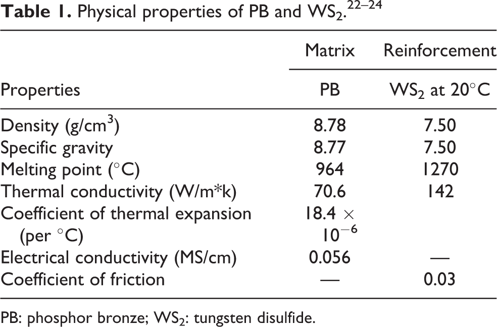
PB: phosphor bronze; WS2: tungsten disulfide.
Reinforcement material
The solid lubricants are usually applied as films on mating surfaces or added to the base material to prevent direct contact of metal surfaces and seizure. It can be able to reduce friction between mating surfaces without the need for liquid lubrication medium. The WS2 is selected as the reinforcement phase, which offers superior dry lubrication compared to other solid lubricants with a coefficient of friction 0.03. 24,25 In the fabrication of PB composites, the reinforcement particle size of 2 µm WS2 is preferred. Some of the physical and mechanical behavior of WS2 is presented in Table 1.
Synthesis of composite
Normally, the MMCs are fabricated by two major techniques like solid-state (powder metallurgy, extrusion, and hot isostatic pressing) and liquid-state (stir casting, squeeze casting, and spray deposition) processes. Among the various techniques, stir casting is the commonly preferred method for the commercial application.
In the fabrication of PBMC, the PB is liquefied in a graphite crucible with a precise furnace temperature of 1100°C. The temperature of the molten metal has been maintained around 1000–1100°C for the time period of 15 min. The addition of magnesium enhanced the wettability and interfacial adhesion among the PB and WS2 composite.
The WS2 reinforcement particles and the mold are preheated to 3000°C and 2000°C, respectively, before the molten metal is poured into crucible. The preheated WS2 particles are poured into the molten state PB matrix and stirred with a rotational speed of 300 r/min. The stirring is carried out to facilitate the incorporation and uniform dispersion of WS2 particles. The PB and WS2 mixer are transferred into the sand mold die and the composite of required sizes is fabricated successfully. After the metal mixer is poured into the die, it is solidified at the atmospheric condition for an hour. Finally, the solidified composite material has been removed from the die. The fabrication of PBMC procedure is shown in Figure 1.

Step-by-step procedure for the fabrication of PBMCs. PBMC: phosphor bronze metal matrix composite.
The different volume percentage (0%, 2%, 4%, 6%, 8%, and 10%) of WS2 reinforcement has been considered for the fabrication of PBMC samples to examine the mechanical and machining characteristics. The fabricated composites (Figure 2) are aimed toward the worm wheel application and it involves machining operations, such as turning and boring. The increasing volume percentage of hard particles into the bronze matrix results in higher hardness, which offers complications in machinability and tool wear. The details of fabricated samples are listed in Table 2. The methodology for the characterization of the PBMC sample is shown in Figure 3.
Samples fabricated by stir casting.
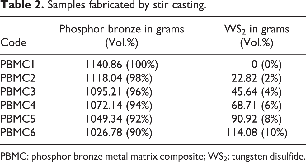
PBMC: phosphor bronze metal matrix composite; WS2: tungsten disulfide.

Composite samples fabricated for boring operation.
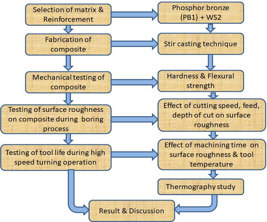
Methodology for the characterization of PBMC. PBMC: phosphor bronze metal matrix composite.
X-Ray diffraction
The X-ray diffraction (XRD) method is used for phase recognition of a crystalline material, which offers depth evidence about crystalline compounds and quantifications of crystalline phases. The XRD plot obtained between intensity and 2θ diffraction angle in 6% WS2-reinforced composite is shown in Figure 4. The peaks observed in the image show a significant presence of copper sulfide (Cu2S) and the tungsten phase in composites along with base copper and tin constituents.

XRD image of 6% WS2 reinforcement composite. WS2: tungsten disulfide; XRD: X-ray diffraction.
Physical and mechanical characterization
Composite density
The prepared composite’s density has been determined experimentally by the Archimedes principle. The density measurement is accomplished in PBMC samples underwater and air environment using microbalance with an accuracy of 0.001 g.
Hardness test
The Brinell hardness test is performed with the 10-mm-diameter steel ball intender and an applied load of 500 kg. The indentation time of 30 s is maintained in each test and the three different indentation spots are identified in each sample.
Flexural strength
As per ASTM 399-90, the single-edge notched beam samples are prepared with 100 mm (L) × 8 mm (W) × 16 mm (B) (Figure 5). The samples are subjected to a three-point bend test with a 10-mm-diameter roller support and a span distance of 64 mm is maintained between the roller supports (Figure 6). A 4-mm (depth) notch is prepared on each sample and the universal testing machine is preferred to estimate the flexural strength with a crosshead speed of 0.5 mm/min. The following mathematical relation is preferred to estimate the flexural strength of the PBMC samples. The mathematical expression 26 includes the load at fracture (F), the length between support rollers (L), sample breadth (B), and sample depth (W)


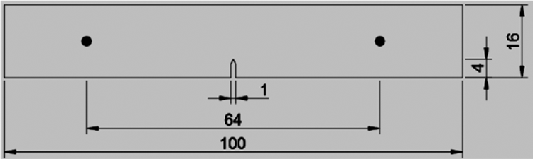
ASTM bend test samples (change).

Experimental setup for three-point bending test.
The flexural strain is estimated by the mathematical expression (2), and the extreme deflection at the beam center (D), depth of the samples (W), and length between support rollers (L) are considered. The initiation of fracture near the notch is observed in each PBMC sample.
Machining of composite
Boring operation
The machining operations are carried out on a Geedee Weiler Ecoturn 150T CNC lathe with a spindle speed of 4000 r/min (Figure 7). The machine has a Fr of 20 and 25 m/min in traverse x and z axes, respectively. The boring bar of a maximum of 25 mm size is used and the boring operation is performed using DNMG 110404 LP MP 3025 carbide insert (Figure 8(a) and (b)). Water-soluble oil is used as a coolant during this machining operation, which is used in diluted form to provide good lubrication and heat transfer effect. The PBMC samples of the size of 60 mm (outer diameter (OD)), 20 mm (inner diameter (ID)), and 50 mm (length (L)) are prepared (Figure 9) and it is machining into 60 mm (OD), 36.2 mm (ID), and 50 mm (L) to carry out the boring operation by the proper machine tool. The Ra is evaluated by Mitutoyo surface tester SJ-201 P and the stylus moves one forward stroke and one return stroke to measure the Ra of the workpiece. The technical specification of the surface tester is presented in Table 3. The following mathematical expression (3) is preferred to compute the material removal rate in the boring method. The final diameter (D1), initial diameter (D2) of the workpiece, Fr, and spindle speed (N) are considered for the estimation of MRR

Technical specifications of surface tester.


Image of CNC machining setup for the boring process.

Specification of carbide insert for (a) boring and (b) high-speed turning.

Specimen dimension for the boring operation of PBMC + 8% WS2. (a) Before machining and (b) after machining. PBMC: phosphor bronze metal matrix composite; WS2: tungsten disulfide.
High-speed turning operation
The effect of WS2 particles on tool temperature and a high-speed turning operation is carried out on 8% WS2-reinforced PBMC sample. The PBMC samples of size 65 mm diameter and 85 mm length are fabricated through the stir casting technique. The fabricated PBMC sample is finished to dimensions of 60 mm (OD) and 80 mm length using a proper turning machine tool. The machining operations are carried out on a GD Weiler 150T CNC lathe with carbide insert (CCMT 060204 VP-15TF) cutting tool at a high spindle speed of 3000 r/min and the specifications of the carbide insert are shown in Figure 8(b).
Totally, 40 passes are carried out on PB and PBMC samples with constant machining parameters with the length of the pass as 50 mm, depth of cut of 0.5 mm, and Fr of 0.05 mm/rev. Since the study is focused on the effect of WS2 solid lubricant while machining PB and composite, the entire machining operations are carried out in the unlubricated condition. The Ra of the composite samples is tested using Mitutoyo surface tester SJ-201 P. The temperature induced in the cutting zone from the beginning of the first pass to the end of fourth pass is observed by infrared (IR) camera positioned near to the cutting zone. The position of the workpiece in the machining center and IR camera placed near to the cutting zone is denoted in Figure 10. For every four passes of turning operation, the average temperature induced on PB/PBMC samples and the tool interface is recorded through FLIR software tool Version 6.4., which is interfaced with an IR camera.

CNC machine tool and IR camera setup. IR: infrared.
Microstructure analysis
The surface morphology of the machined surface before and after the boring process with carbide insert is analyzed by SEM with 1000× magnification. The microstructure of the carbide insert tooltip near to the cutting edge is examined using an optical microscope. The samples are mechanically polished and etched with nitric acid (100 mL ethanol, 1–10 mL HNO3 68–70% concentrated: 1–2 min immersion).
Results and discussion
Physical and mechanical characterization
Composite density
The density of the PBMC sample has been determined experimentally using the Archimedes principle. Since the compactness of WS2 particles is 7500 kg/m3, which is less than PB, the WS2 particle reduces the density in PBMC samples compared to base matrix PB. The experimental and theoretical density (rule of the mixture) is nearly the same (Figure 11). The obtained results ensure the suitability of the stir casting technique for the preparation of WS2 self-lubricating PBMC samples.

The density of PBMC samples. PBMC: phosphor bronze metal matrix composite.
Hardness
The Brinell hardness test is conducted on PB and PBMC samples and the hardness value for the percentage of WS2 is shown in Figure 12 and the indentation mark of three spots is shown in Figure 13. The result expresses that the hardness of PB is increased when WS2 particles are added to it. The increment of WS2 particle in PBMC samples from 2% to 10% improves the hardness by 11.85%. The hardness is increased in PBMC sample due to the inclusion of hard WS2 uniform dispersions. The improvement in hardness value is attributed due to hard WS2 particle, which acts as an obstacle to the displacements in the matrix.
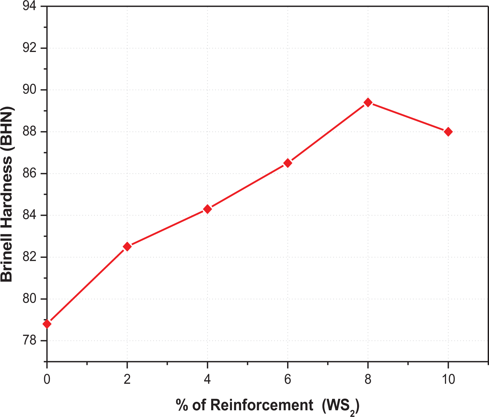
The hardness of PB and PB/WS2 composites. PB: phosphor bronze; WS2: tungsten disulfide.

Hardness test samples (a) PB and (b) PBMC. PBMC: phosphor bronze metal matrix composite; PB: phosphor bronze.
Flexural strength
The flexural strength and flexural strain values obtained by the mathematical expressions (1) and (2) are shown in Figure 14. The addition of WS2 particles improved the flexural strength of PB (Figure 14). The fractured flexural test specimens are shown in Figure 15. The flexural strength of the PBMC sample is predominantly increased with the addition of 8% WS2 particles by 34.14% compared to PB. The increase in flexural strength is attributed to strong interfacial bonding caused by the development of a tiny layer of Cu2S on the matrix phase. 27 The addition of WS2 particles more than 8% reduced the flexural strength by 1.24% due to agglomeration to WS2 particle in the PBMC matrix. The flexural strain value is increased by up to 43.75% compared to PB. There is an increasing trend in flexural strain found on the PBMC samples by the addition of WS2 particles between 10% and 43.75%. The obtained results reveal that the addition of WS2 particles contributes to the improvement of flexural strength in the self-lubricating PBMC samples.
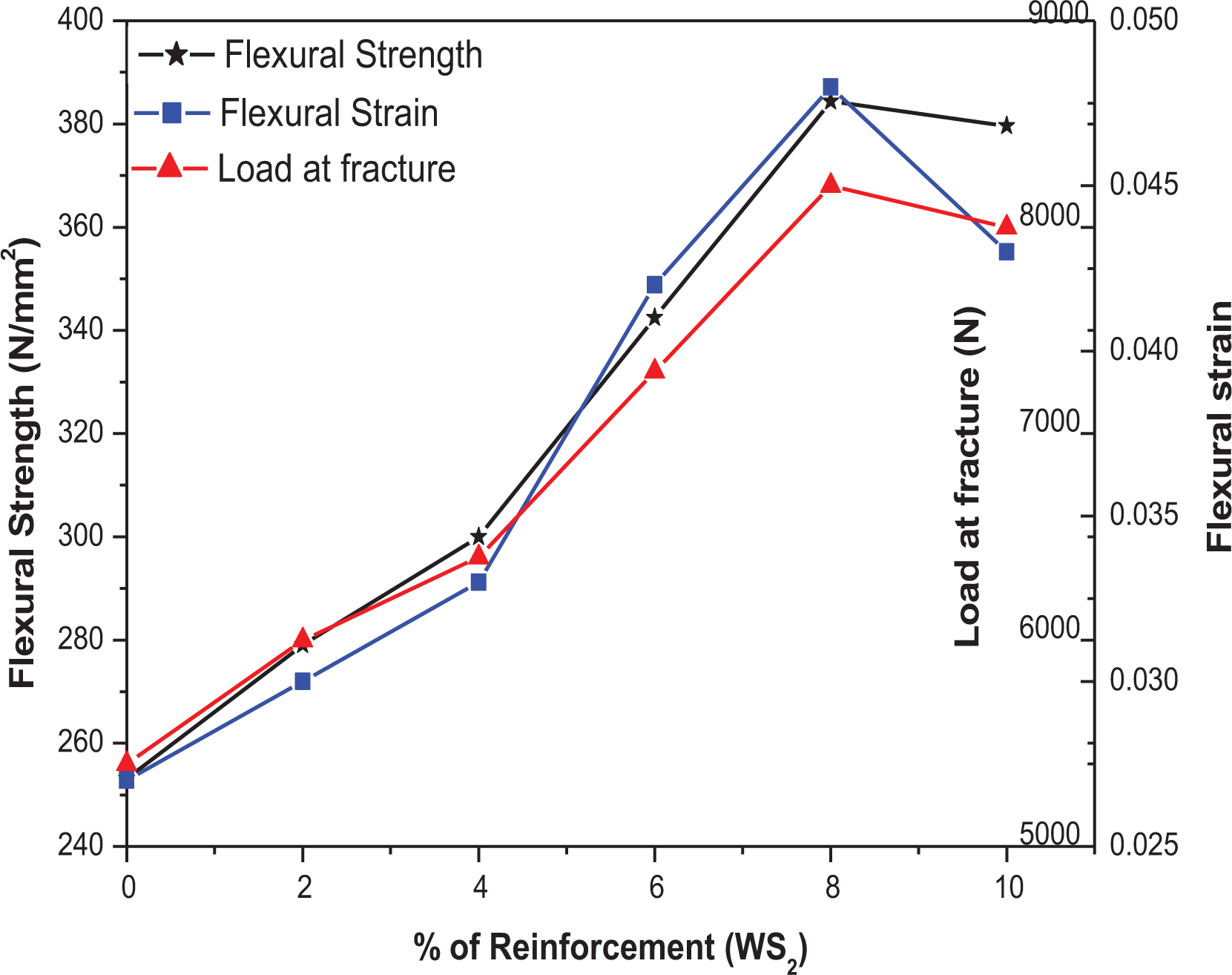
Flexural strengths of PB and PB/WS2 composites. PB: phosphor bronze; WS2: tungsten disulfide.
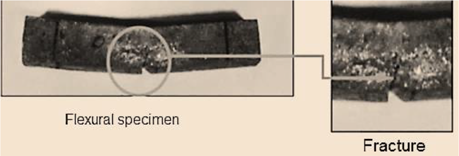
Fracture on 6% WS2 composite samples. WS2: tungsten disulfide.
Machining of composite
Boring operation
The PBMC samples are machined with 0.2 mm depth and the Ra is estimated using SJ-201 P Pick-ups (Ra tester) (Figures 16 and 17). The design of the experiment is prepared, and the machining parameters are presented in Table 4.
Machining parameter and their levels.


Surface roughness for 0.2 mm depth of cut on PB sample. PB: phosphor bronze.

Surface roughness for 0.2 mm depth of cut on PBMC + WS2. PBMC: phosphor bronze metal matrix composite; WS2: tungsten disulfide.
For various range of spindle speed (600–1200 r/min) and Fr (0.02–0.1 mm/rev), the Ra is amplified in the PB and PBMC samples (Figures 19 and 20). This results in a rise in temperature, which consequences the tool wear, and increases in Ra value. 28 At 600 r/min of spindle speed, the Ra is improved up to 12.32% in PB and 18.64% in PBMC composite. At 1200 r/min of spindle speed and increasing Fr from 0.02 to 0.1 mm/rev, the Ra is improved up to 30.3% in PB and 16.66% in PBMC composite. For the depth of cut 0.2 mm at all levels of Fr, the Ra is enhanced due to the rise in spindle speed from 600 r/min to 900 r/min attributed to the creation of discontinuous chips. The periodical slip has occurred during machining of PB, which creates a small magnitude of vibration on tools that resulted in an escalation of Ra. At a higher spindle speed of 1200 r/min run, the Ra is reduced compared to the roughness values obtained at 900 r/min. At the low depth of cut, the rough surface is appeared owing to the formation of built-up-edge (BUE) and the chip failure. The rise in spindle speed diminishes the chip fracture and the BUE formation, which indicates the reduction in Ra. 29
The nature of variation obtained on Ra of PBMC is the same as PB between the spindle speeds of 600 and 900 r/min (Figures 18 and 19). For the 0.2-mm depth of cut, the Ra results obtained on PBMC samples corresponding to all levels of Fr are higher than PB. The greater Ra on the PBMC sample due to porosity/tearing out of WS2 particles is compared with the PB sample. The formation of a torn WS2 particle layer on the edge of the cutting tool (carbide insert) subsidizes to the surge in Ra on the PBMC sample. 30 Similarly, the measured Ra obtained for the 0.6-mm depth of cut is analyzed. At a spindle speed 600 r/min, increasing Fr (0.02–0.1 mm/rev) has enhanced the Ra up to 41.78% in PB and 77.6% in PBMC composite. Similarly, at 1200 r/min (spindle speed), the Ra is increased up to 20.61% in PB and 26.72% in PBMC composite (Figures 18 and 19).

Surface roughness for 0.6-mm depth of cut on PB sample. PB: phosphor bronze.

Surface roughness for 0.6-mm depth of cut on PBMC + 8% WS2. PBMC: phosphor bronze metal matric composite; WS2: tungsten disulfide.
The measured values of Ra on the PB and composite samples for the depth of cut of 1 mm are plotted in Figures 20 and 21. At a spindle speed of 600 r/min, the Ra increased up to 33.62% in PB and 52.56% in PBMC composite. At 1200 r/min of spindle speed, for the increase of Fr from 0.02 mm/rev to 0.1 mm/rev, the Ra increased up to 28.17% in PB and 26.96% in PBMC composite.

Surface roughness for 1-mm depth of cut on PB sample. PB: phosphor bronze.
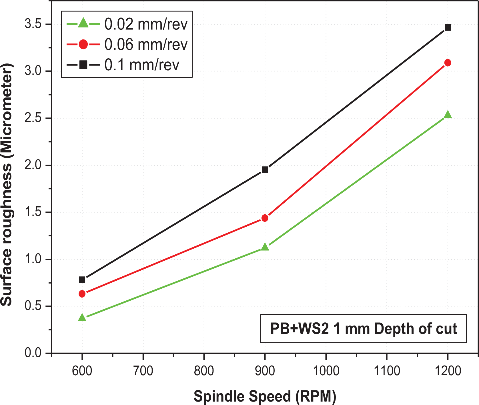
Surface roughness for 1-mm depth of cut on PBMC + 8% WS2. PBMC: phosphor bronze metal matrix composite; WS2: tungsten disulfide.
High-speed turning operation
The Ra of PB and PBMC samples on the effect of turning passes is studied (Figure 22). It is observed from the results that the Ra values are increasing from 0.012 µm to 0.016 µm while machining PBMC1 with definite machining parameters. When compared to the roughness value obtained after four passes, the Ra increased up to 33.33% at the end of 40 passes. The Ra values measured on PB and PBMC samples after every four passes are shown in Figure 22. The Ra of 8% WS2-reinforced PB composite initially increases from 0.009 to 0.013 for an increase of a number of passes from 4 to 16. After that, a decrease in roughness is observed at the beginning of the 20th pass to the end of the 40th pass. It is identified from the results that the roughness value decreased to 36.33% from 20th pass to 40th pass in composites. The measured Ra values at the end of each set of passes of PB+WS2 and PB composite is shown in Figure 22.
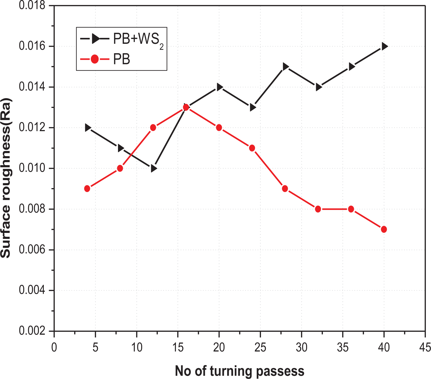
The surface roughness of PB and PB + 8% WS2 composites. PB: phosphor bronze; WS2: tungsten disulfide.
The maximum temperature induced near to the cutting edge of the carbide insert at the end of each set (four passes) obtained from FLIR tool software is given in Table 5. The maximum temperature induced in the cutting zone from the starting to end of a single-pass is recorded. Similarly, the maximum temperature values in another three individual passes are also recorded. An average maximum temperature induced among four passes is found as 70.3°C. In a similar way, the average maximum temperatures after every four passes are noticed and considered for comparison. The result shows that an overall average of maximum temperature 72.8°C is induced on the cutting zone when high-speed machining is performed on PBMC1. While machining PBMC4-reinforced PB composite, an average of 65.9°C is induced near the cutting edge. It is also observed from Figure 23 that for all sets of readings, the temperature induced on cutting edge of the insert during the machining of composite material is lower than the temperature values obtained during machining of PBMC1. The results revealed that the inclusion of WS2 solid lubricant particles as reinforcement in PB is contributing well to the reduction of cutting tool temperature, which results to increase in tool life.
The temperature at the cutting edge of carbide insert.

WS2: tungsten disulfide.

Temperatures at tip of insert while machining PB and PBMC + WS2. PB: phosphor bronze; PBMC: phosphor bronze metal matrix composite.
The thermography image obtained from an IR camera while machining PB is the first four passes that are shown in Figure 24(a). By giving suitable emissivity value in the camera, the temperature induced in different zones is obtained from FLIR software. 31 From the thermograph, the maximum, minimum, and average values of temperature induced at any point within the cutting zone can be taken for analysis. By observing the different colors from the image, the hot and cold zones are differentiated and it is denoting the temperature variation at different points. The thermography image obtained from the IR camera while machining PB/WS2 composite samples in the first four passes is shown in Figure 24(b).

Thermograph images obtained while machining (a) PBMC1 and (b) PBMC + WS2. PB: phosphor bronze; PBMC: phosphor bronze metal matrix composite; WS2: tungsten disulfide.
Microstructure analysis
The dispersion of reinforcement (WS2) in the matrix is ensured with the aid of a SEM images. The SEM images of pure PB and PB composites reinforced with 8% of WS2 particles are shown in Figure 25(a) and (b), respectively. The SEM image shown in Figure 25(c) and (d) shows that the WS2 particles are well distributed in the PB matrix and provide good adhesion between the PB matrix and WS2.

SEM images of (a, b) phosphor bronze and (c, d) PBMC + 8% of WS2. PB: phosphor bronze; PBMC: phosphor bronze metal matrix composite; WS2: tungsten disulfide.
The microstructure of the tool surface near to cutting edge is examined using an optical microscope. Figure 26 shows the microstructure of the carbide insert before machining. It is observed from the images that the surface of the tool is clean and smooth before machining. The microstructure of cutting edge after machining of PBMC1 has shown in Figure 27, which exposes some abrasive nature of wear traces. Similarly, the microstructure of cutting edge after machining PB/WS2 composite is obtained from the microscope and it is shown in Figure 28 that some traces of WS2 layers are observed on the edge of carbide insert, which is obtained from the composite workpiece during the machining process.

The microstructure of carbide insert before machining.
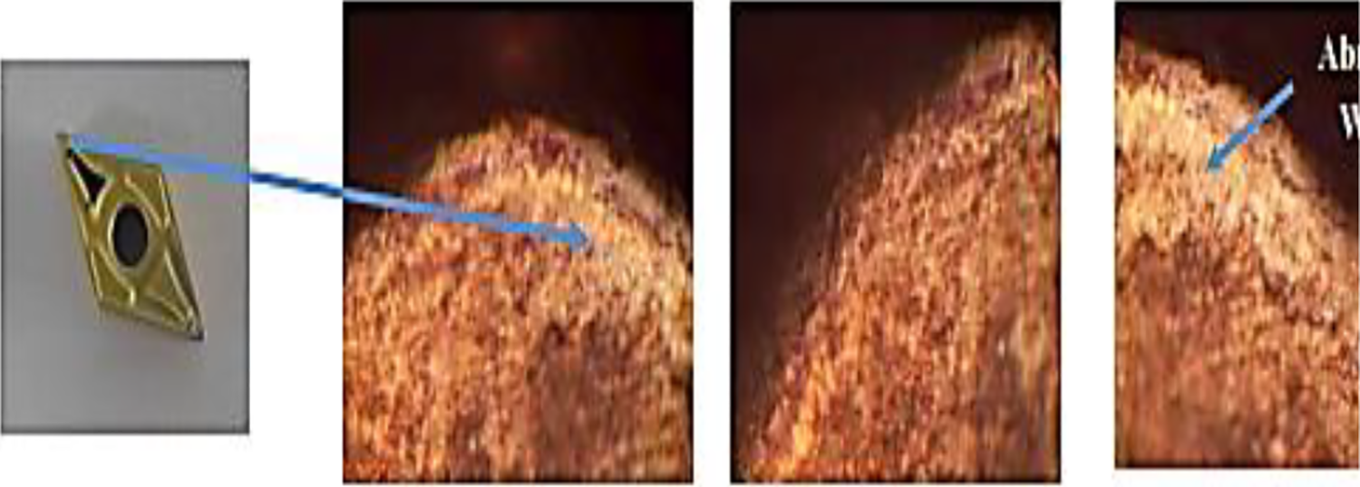
The microstructure of carbide insert after machining phosphor bronze.
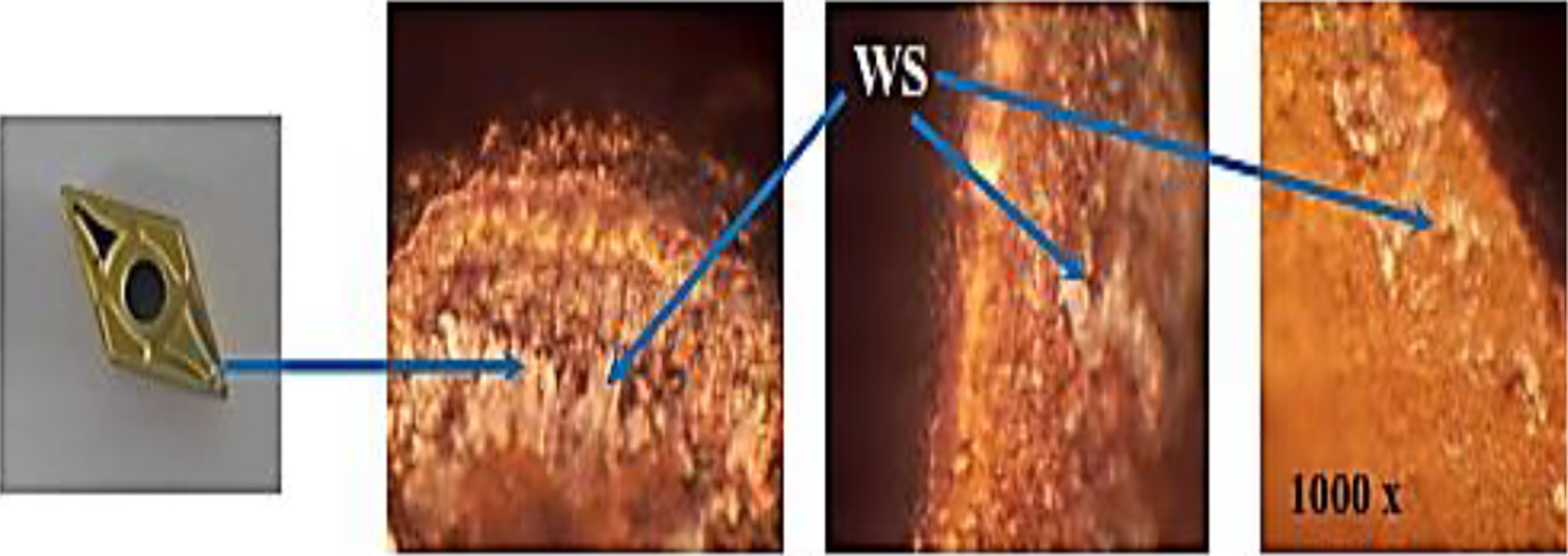
The microstructure of carbide insert after machining phosphor bronze/WS2 composites. WS2: tungsten disulfide.
By observing the temperature results obtained on insert edge during machining of composite samples and the corresponding microstructure images, it is evidenced that the formation of the WS2 layer on carbide insert played a significant role in the reduction of tool temperature.
Conclusions
This work is carried out to govern the effect of WS2 solid lubricant reinforcements on the mechanical and machining behavior of stir-casted PB composite materials. From the exhaustive investigations on these PBMC samples, the following conclusions are analyzed. The flexural strength is increased in between the range of 9.29–34.14% when the WS2 particles are reinforced from 2% to 10%. The maximum flexural strength (34.14%) is observed in the PBMC4 sample compared to PBMC1. At higher spindle speed (1200 r/min) and depth of cut (0.2–1 mm), the Ra is reduced in PBMC1 compared to other PBMC samples at 900 r/min. An average temperature (65.97°C) is obtained from the thermography study on the cutting edge of the insert while machining 8% WS2-reinforced PBMC4 is lower than the average temperature (72.84°C) of PBMC1, which enhances the tool life.
Supplemental material
Supplemental Material, ACM-20-0101-14th_Aug_20_Reply_to_Reviewer_Comments - Significance of tungsten disulfide on the mechanical and machining characteristics of phosphor bronze metal matrix composite
Supplemental Material, ACM-20-0101-14th_Aug_20_Reply_to_Reviewer_Comments for Significance of tungsten disulfide on the mechanical and machining characteristics of phosphor bronze metal matrix composite by P Sangaravadivel, G Rajamurugan and Prabu Krishnasamy in Advanced Composites Letters
Footnotes
Declaration of conflicting interests
The author(s) declared no potential conflicts of interest concerning the research, authorship, and/or publication of this article.
Funding
The author(s) received no financial support for the research, authorship, and/or publication of this article.
Supplemental material
Supplemental material for this article is available online.
References
Supplementary Material
Please find the following supplemental material available below.
For Open Access articles published under a Creative Commons License, all supplemental material carries the same license as the article it is associated with.
For non-Open Access articles published, all supplemental material carries a non-exclusive license, and permission requests for re-use of supplemental material or any part of supplemental material shall be sent directly to the copyright owner as specified in the copyright notice associated with the article.