
Abstract
Thin-walled workpieces of silicon carbide particle-reinforced aluminum matrix (SiCp/Al) composites with outstanding properties have been widely applied in many fields, such as automobile, weapons, and aerospace. However, the thin-walled workpieces exhibit poor rigidity, large yield ratio, and easily deform under the cutting force and cutting heat during the machining process. Herein, in order to improve the processing efficiency and precision of higher volume fraction SiCp/Al composite thin-walled workpieces, the influence of different high-speed milling parameters and machining paths on the edge defects is analyzed. The results reveal that the cutting force initially increased and then decreased with the cutting speed. Besides, the cutting force steadily increased with radial cutting depth and feed per tooth, but the influence of feed per tooth is less than radial cutting depth. After up-milling cut-in and cut-out processing and down-milling cut-out processing, the cut-in end of the workpiece exhibited higher breakage and obvious edge defects. However, the workpiece edges remained intact after down-milling cut-in processing. In conclusion, a higher cutting speed, a smaller radial cutting depth, and moderate feed per tooth are required to decrease the cutting force during the milling of SiCp/Al composite thin-walled workpiece. Furthermore, down-milling cut-in processing mode can reduce the edge defects and improve the processing efficiency and precision of the workpiece.
Introduction
Silicon carbide particle-reinforced aluminum matrix (SiCp/Al) composites are a typical example of particle-reinforced metal–matrix composites, where Al and SiC particles are the matrix and reinforcement, respectively. Owing to a series of excellent properties, including lightweight, superior wear resistance, and small thermal expansion coefficient, SiCp/Al composite thin-walled workpieces have been employed in a wide range of applications, such as automobiles, electronics, weapons, and aerospace. 1,2 However, the thin-walled workpieces still show some shortcomings during machining, such as poor rigidity and high material removal area. In addition, because of the presence of SiC particles, the processing mechanism of composites is different from that of single metal material. Therefore, different processing technologies are being explored for SiCp/Al composites. 3
By reviewing the research status of the electric spark machining method for SiCp/Al composites, Kandpal and Singh pointed out that neural network, gray-scale correlation, and genetic algorithm can be used for the optimization of machining parameters. Moreover, it has been demonstrated that the combination of electric spark technology with surface grinding, abrasive water jet, and electrochemical machining can enhance the machining quality of SiCp/Al composites. 4 Müller and Monaghan compared laser processing characteristics with electric spark machining and concluded that laser processing renders a higher metal removal rate than electric spark machining. However, the workpiece was subjected to a higher thermal load during laser processing. Moreover, the cutting width and surface roughness were found to be critical parameters in terms of laser processing quality. 5 Xu et al. performed ultrasonic vibration (UV) cutting on SiCp/Al composites and demonstrated small chip deformation, low surface roughness, and stable cutting process. Accordingly, it has been concluded that UV-assisted cutting is appropriate for precision cutting of SiCp/Al composites. 6 Zhou’s and Huang’s research groups have carried out finite element simulations to assess temperature distribution under different grinding conditions and demonstrated excellent consistency between the simulation and experimental data. 7 –9
Furthermore, the grinding characteristics of SiCp/Al composites under freezing were investigated. Liu et al. focused on the grinding-electrochemical discharge machining (G-ECDM) method, which includes three processes, that is, electrochemical melting (ECM), electrical discharge machining (EDM), and direct mechanical grinding. During the G-ECDM process, the electrolyte provides a finite amount of current to the tool electrode and workpiece, and the matrix phase dissolves during the ECM process. A relatively large discharge gap is generated to ensure the successful proceeding of EDM and promote the formation and removal of chips. 10 –12 Ge et al. and Bian et al. carried out high-speed precision cutting of SiCp/Al composites and obtained the mirror-level machined surface with a surface roughness (Ra) of approximately 20–30 nm. However, some surface defects, such as pits, cavities, and micro-cracks, were observed on the finished surface under scanning electron microscope and atomic force microscope. 13,14 Deng et al. focused on the machining process of particle-reinforced composites by a ball-end mill and adopted the milling force modeling method based on the cutting depth. 15 Moreover, they have calculated the particle-debonding force in shear and accumulation zones. The shear force of the matrix and the frictional force between the workpiece and cutter, corresponding to the friction coefficient, varied with the addition of reinforcement particles. 16 Han et al. examined the milling quality (Ra) of SiCp/Al composites by considering the grain size of polycrystalline diamond (PCD) cutter and structural characteristics of the blade. It has been demonstrated that the Ra value increased and decreased with increasing feed per tooth and cutting depth, respectively. However, Ra value was slightly affected by the blade structure. 17 Malghan et al. employed different techniques to analyze the influence of different parameters on milling surface (Ra) of SiCp/Al composite, showing the dominant role of cutting speed, followed by feed per tooth and cutting depth. 18,19
Although there are many reported literatures on SiCp/Al composites, the publications on the machining study of higher volume fraction SiCp/Al composite thin-walled workpieces are relatively scarce. In this research, with high-speed milling experiment, the influence of milling parameters, such as cutting speed, radial depth, and feed per tooth on cutting force, and machining paths on the edge defects is analyzed. It can provide a basis for optimizing cutting parameters and machining paths to improve machining precision and efficiency of SiCp/Al composite thin-walled workpieces.
Experimental equipment
Machine tool
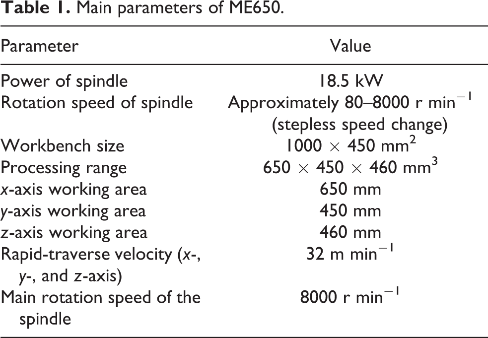
Herein, the high-speed machining center (ME650, EUMA-SPINNER Corporation, Taiwan, China), featured by high precision, large power, favorable rigidity, and simple operation, was used as the machine tool. Moreover, ME650 is suitable for large-scale production and extensively used for high-speed milling of Al-based structural parts in various industries, such as aerospace, automobile, and electronics. In contrast to similar products in Chinese Mainland, ME650 exhibits remarkably enhanced machining precision, production efficiency, and cost-effectiveness. The machining precision and surface roughness (Ra) can reach up to IT6 level and 0.8, respectively. Figure 1 shows the ME650 high-speed vertical machining center and Table 1 lists some parameters of the vertical machining center.

ME650 vertical machining center.
Main parameters of ME650.
Workpiece
The thin-walled rectangular plate, with a length of 51 mm, a height of 47 mm, and a thickness of 2 mm, was used as the workpiece. The workpiece was made up of SiCp/Al composite, where SiC particles (60 µm) occupied 56% in volume. Table 2 lists the physical and mechanical properties of SiCp/Al composites.
The physical and mechanical properties of SiCp/Al composites.

SiCp/Al: silicon carbide particle-reinforced aluminum matrix.
Figure 2 shows the overall appearance and metallographic structure of the SiCp/Al composite, where SiC particles and Al matrix are represented by dark irregular geometry and light-colored grains, respectively. It can be readily observed that SiC particles exhibit uniform distribution and occupied a large proportion.
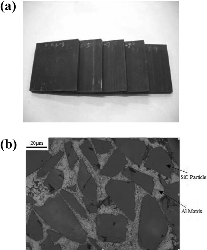
Workpiece: (a) the overall appearance of the workpiece and (b) the metallographic structure of the workpiece.
Cutter
The PCD single-tooth end mill was used as shown in Figure 3. The rake angle, cutting edge inclination, and clearance angle were set at 10°, 5°, and 8°. The main and minor cutting edge angles were 90° and 0°, respectively. The cutter diameter was 16 mm.

The overall appearance of the cutter.
Experimental measurement system
Cutting force measurement system
Figure 4 presents the cutting force measurement system in the present milling experiment. Figure 4(a) shows the operating process of the measurement system, whereas Figure 4(b) illustrates the working principle of the system. First, the analog electronic signal of the cutting force was measured by the cutting force measurement system (9123C, Kistler Instrument Company, Switzerland). Then, the electrical signal was converted into a digital signal by the data acquisition card after filtering and amplification via the charge amplifier. Finally, the digital signal was provided to the computer for data analysis and processing, and acquired actual cutting force data.

Cutting force measurement system: (a) actual operating process and (b) working principle.
Observation system of edge defects
The edge defects of the workpiece were observed under the 3D stereoscopic microscope (VHX-1000, Keyence Co., Ltd, Japan) as shown in Figure 5. Several characteristics of the VHX-1000 digital microscopic, such as vivid and clear 3D observation, rapid and true observation, and ultra-high resolution, could realize superfield imaging over 20 times. The current study employed the depth of the VHX-1000C digital microscopic system for fast photomontage to observe the edge defects of the workpiece.

The VHX-1000 digital microscopic system.
Experimental scheme and cutting force results
Experimental scheme
The cutting speed, radial cutting depth, and feed per tooth were used in a single-variable experiment to examine their respective influence on the cutting force. For each setting, a single-feeding down-milling and single-feeding up-milling were performed to investigate the effect of down-milling, up-milling, and cutting parameters.
(1) When the feed per tooth (fz
), radial cutting depth (ae
), and axial cutting depth (ap
) were fixed at 0.1 mm/z, 0.3 mm, and 4 mm, respectively, the effect of cutting speed on cutting force was investigated (Table 3). When the cutting speed (v), radial cutting depth (ae
), and axial cutting depth (ap
) were fixed at 300 m min−1, 0.3 mm, and 4 mm, respectively, the effect of feed per tooth on the cutting force was investigated (Table 4). When cutting speed (v), feed per tooth (fz
), and axial cutting depth (ap
) were fixed at 300 m min−1, 0.1 mm/z, and 4 mm, respectively, the effect of radial cutting depth on the cutting force was investigated (Table 5).
The influence of cutting speed on cutting force.

The influence of feed per tooth on cutting force.

The influence of radial cutting depth on cutting force.

Cutting force signals
Furthermore, the up-milling of the workpiece was carried out at v = 60 m min−1, fz = 0.1 mm/z, ap = 4 mm, and ae = 0.3 mm, and cutting force curves were obtained along three directions (x-, y-, and z-direction). Figure 6 shows the cutting force in 10 periods in the middle of the cutting process.

The measured results of the cutting force: (a) Fx signal, (b) Fy signal, and (c) Fz signal.
As shown in Figure 6, the cutting forces (Fx and Fy ) fluctuated periodically as cut-in and cut-out milling process occurred alternately, which was the characteristic of single-tooth milling cutter. The cutter tooth only touched the workpiece once during rotation of the cutter. Hence, the workpiece had sufficient time to remove chips and dissipate heat. Since Fz was only affected by the elastic restoring force of the machined surface, which was quite small at a small radial cutting depth, Fz can be regarded as the vibratory force of the cutter. The vibrations were mainly related to the properties of SiCp/Al composites. The volume fraction of SiC-reinforced particles in the composites reached up to 56%. Therefore, the composites were overall brittle and noncontinuous chips were produced during the machining process. Under the cutter action, flaky or crushed chips were formed, which led to significant fluctuation of the cutting force. Moreover, owing to the poor rigidity, the thin-walled workpiece was easily deformed and the cutter was also relieved under the action of periodic cutting force, which also caused undesirable vibrations.
As the rigidity varied with the position of thin-walled workpiece along the feeding length direction, the deformation at both ends and center of the workpieces were different. The cutting force varied at different positions. Therefore, the current study selected three cutting areas, that is, 5 mm at the beginning, 5 mm in the middle, and 5 mm at the end of the cutting process, and calculated mean peak cutting force in each region. However, the axial cutting force (Fz ) was mainly induced by the vibrations and varied slightly. Therefore, Fz in the whole cutting region was selected for further analysis.
Influence of cutting speed on cutting force
At fz = 0.1 mm/z, ae = 0.3 mm, and ap = 4 mm, the cutting speed was varied during down-milling and up-milling, and mean peak cutting force was measured at three different cutting areas. Figure 7 displays the variation curves of cutting force with cutting speed. It can be observed that the cutting force during the up-milling process remained higher than the down-milling process. Moreover, Fx and Fy initially increased with increasing cutting speed, and then gradually decreased with the cutting speed greater than 250 m min−1, which can be ascribed to the increase in temperature and, in turn, thermal softening of the workpiece. This softening can lead to a reduction of friction coefficient between workpiece and the front cutter, which further reduced the cutting force. Moreover, the deformation coefficient of the chips decreased with the increase of the milling temperature, which corresponds to lower deformation energy and reduces the cutting force per unit area. From the viewpoints of cutter service life and machining efficiency, the cutting speed should be high for the machining of SiCp/Al composite thin-walled workpiece. Moreover, the value of Fz was too small and less affected by the radial cutting depth.
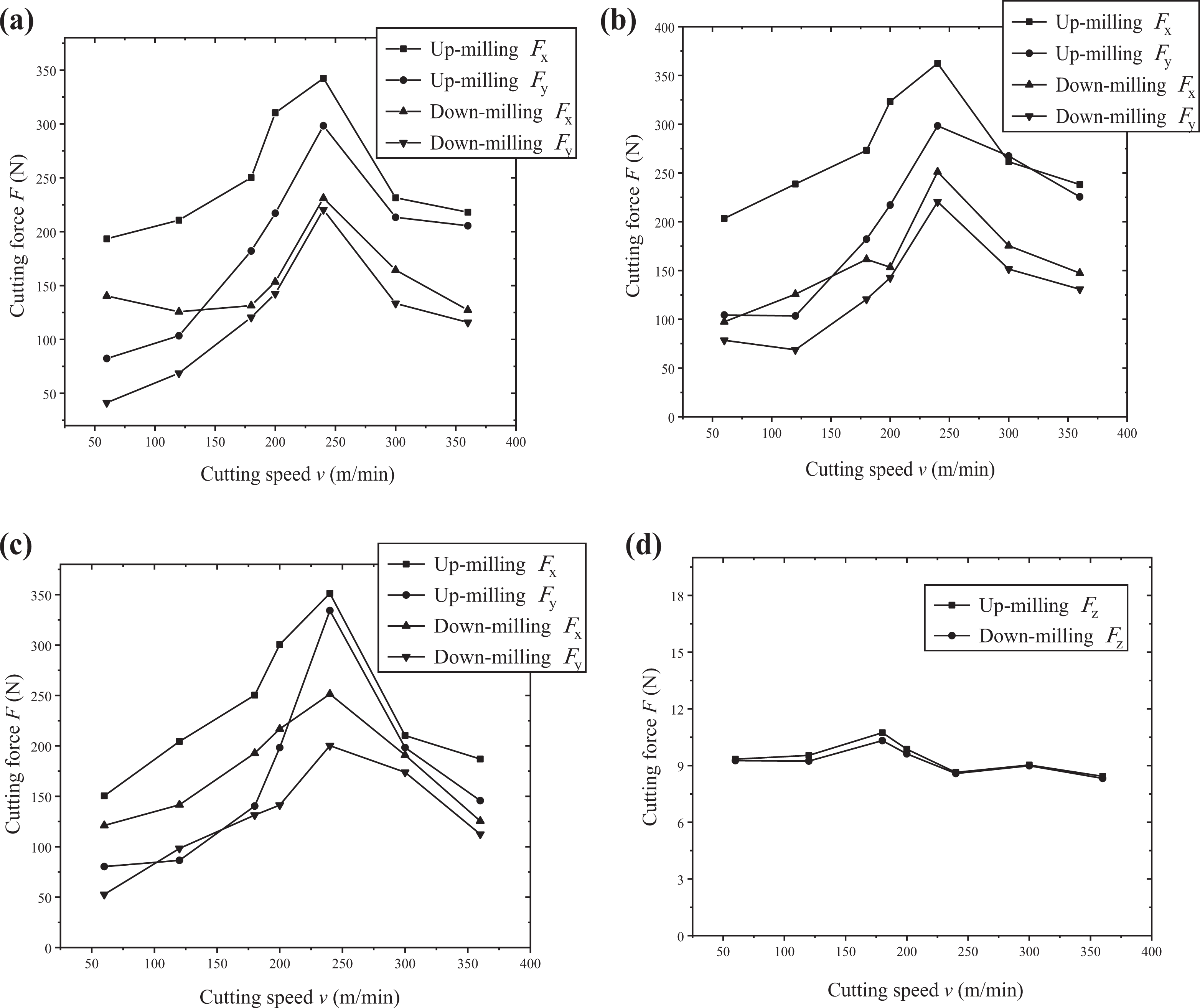
The variation curves of the cutting force with cutting speed: (a) the variation curves of Fx and Fy at the beginning of the cutting process, (b) the variation curves of Fx and Fy in the middle of the cutting process, (c) the variation curves of Fx and Fy at the end of the cutting process, and (d) the variation curves of Fz in the whole cutting region.
Influence of cutting depth on cutting force
As mentioned earlier, the cutting force during up-milling process was higher than the down-milling process. Therefore, down-milling process was selected to analyze the influence of radial cutting depth and feed per tooth. At v = 300 m min−1, fz = 0.1 mm/z, and ap = 4 mm, the cutting depth was varied from 0.1 mm to 0.5 mm and mean peak cutting force was measured at each cutting area. Figure 8 displays the variation curves of the cutting force with the radial depth. It can be observed that the cutting force significantly increased with the increase of the radial cutting depth (ae ). This is because that the area of the cutter layer per unit time increased with the increase of the cutting depth, which also increased the elastic-plastic deformation and frictional force between workpiece and the front cutter. Moreover, similar to the cutting speed, the value of Fz was too small and less affected by the radial cutting depth.

The variation curves of the cutting force with radial cutting depth: (a) the variation curves of Fx and Fy at the beginning of the cutting process, (b) the variation curves of Fx and Fy in the middle of the cutting process, (c) the variation curves of Fx and Fy at the end of the cutting process, and (d) the variation curves of Fz in the whole cutting region.
Influence of feed per tooth on cutting force
At v = 300 m min−1, ae = 0.2 mm, and ap = 4 mm, the feed per tooth fz was varied from 0.05 mm s−1 to 0.25 mm s−1 and mean peak cutting force was measured at three different cutting areas. Figure 9 shows the variation of cutting force with the fz . Fx and Fy also increased with the increase of fz . This is because that the cutting area per unit time increased with the increase of feed per tooth, which increased the deformation energy and, in turn, increased the cutting force. When the cutting speed is increased, a slight change in fz renders a negligible effect on the cutting force. However, if lower fz is selected, the milling efficiency is greatly reduced. Therefore, at a high cutting velocity, the milling efficiency can be enhanced by increasing the value of fz .
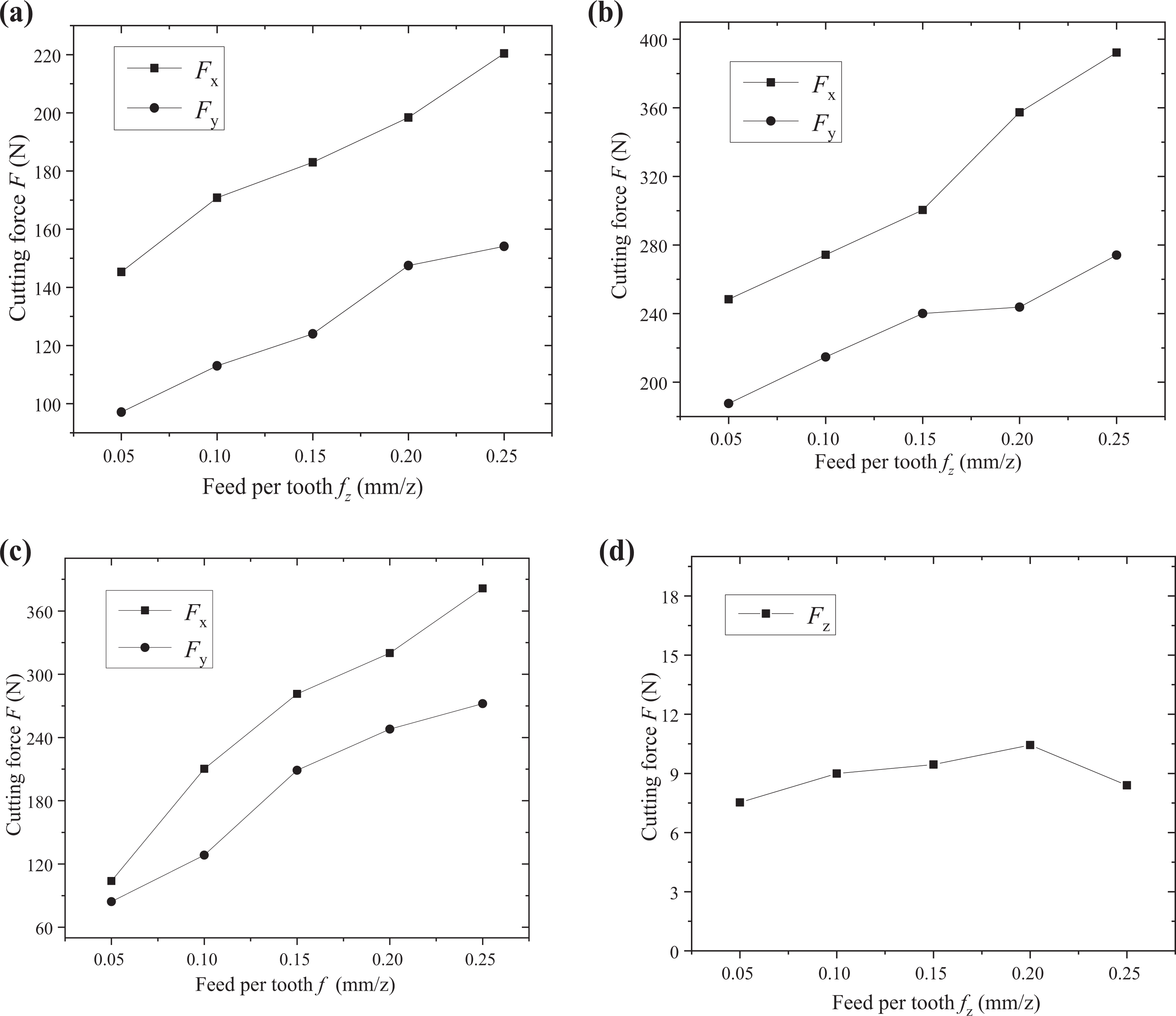
The variation curves of the cutting force with feed per tooth: (a) the variation curves of Fx and Fy at the beginning of the cutting process, (b) the variation curves of Fx and Fy in the middle of the cutting process, (c) the variation curves of Fx and Fy at the end of the cutting process, and (d) the variation curves of Fz in the whole cutting region.
Experimental scheme and edge defect results
Experimental scheme
In the present experiment, the cutting velocity (v) and feed per tooth (fz ) were set at 300 m min−1 and 0.1 mm/z. And the axial cutting depth ap and radial cutting depth ae were set at 4 and 0.5 mm. A workpiece was cut twice by a milling cutter. Figure 10 presents the feeding processes and Figure 11 shows the actual condition of the thin-walled workpiece at different processing times (t).
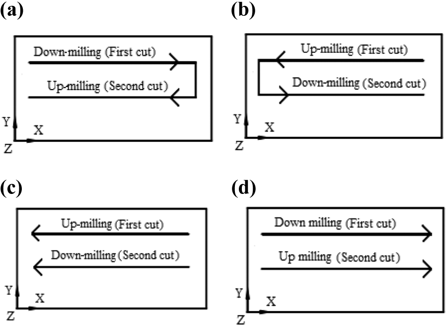
The feeding processes with different processing paths: (a) scheme 1 (zigzag path), (b) scheme 2 (zigzag path), (c) scheme 3 (one-way path), and (d) scheme 4 (one-way path).

The actual machining process of the thin-walled workpiece at different processing times (t): (a) t = 1.2 s, (b) t = 6.5 s, (c) t = 12.1 s, and (d) t = 13.4 s.
Influence of machining paths on edge defects
The machining of SiCp/Al composite thin-walled workpiece was hindered by the low toughness and high brittleness. The edge of the workpiece was easily broken, crushed, or peeled off under the action of cutter. These edge defects affect the structural integrity and geometrical shape of the workpiece, which, in turn, influence the sealing performance and assembly quality. More seriously, the service life of the workpiece is compromised. Figure 12 presents the microscopic images of the processed SiCp/Al composite thin-walled workpieces using different milling schemes. As shown in Figure 12(a) panel 1, using the scheme 1, the edge exhibited intact interface after the first down-milling cut-in, however, the edge exhibited severe defects after the second up-milling cut-out. Figure12(b) panel 2 shows the edge of the processed workpiece using scheme 2, exhibiting obvious edge defects after the first up-milling cut-in and the second down-milling cut-out. Figure 12(b) panel 3 shows that the utilization of scheme 3 resulted in the higher breaking of the cut-in end of the workpiece after the first up-milling cut-in. Then, the defects became less obvious and the edge exhibited favorable quality after the second down-milling cut-in. In Figure 12(a) panel 3 using scheme 3, the cut-out end of the workpiece exhibited obvious breaking after the up-milling and down-milling cut-out. Figure 12(b) panel 4 shows that the utilization of scheme 4 rendered a large number of edge defects on the cut-in end of the workpiece surface and obvious breakage and peeling off after the two times cut-out. Moreover, in Figure 12(a) panel 4, the workpiece remained intact without obvious edge defects after the down-milling cut-in. In conclusion, the edge defects could be caused by up-milling cut-in, cut-out, and down-milling cut-out. But the edge exhibited intact interface after down-milling cut-in. Therefore, different cut-in and cut-out milling modes should be reasonably selected for the thin-walled workpiece with high requirements on edge quality.

The edge defects on the processed workpieces using different milling schemes. (a) Edge defects on the left end of the workpieces: (a-1) scheme 1 (zigzag path), (a-2) scheme 2 (zigzag path), (a-3) scheme 3 (one-way path), and (a-4) scheme 4 (one-way path). (b) Edge defects on the right end of the workpieces: (b-1) scheme 1 (zigzag path), (b-2) scheme 2 (zigzag path), (b-3) scheme 3 (one-way path), and (b-4) scheme 4 (one-way path).
Conclusions
In summary, the milling process of higher volume fraction SiCp/Al composite thin-walled workpieces using a PCD single-tooth end mill under dry cutting conditions has been analyzed. The cutting force was measured by the rotating dynamometer and edge defects were observed under the 3D stereoscopic microscope. Moreover, the influence of cutting speed, radial depth, and feed per tooth, as well as different processing paths on cutting force and edge defect has been systematically investigated.
The results demonstrate that the cutting force initially increased and then decreased with increasing cutting speed. Under this experimental condition of this study, the threshold limit of cutting speed is 250 m min−1. Moreover, the cutting force significantly increased with the increase of cutting depth and feed per tooth, but the influence of feed per tooth is less than radial cutting depth. After up-milling cut-in, cut-out, and down-milling cut-out processing, the end of the workpiece exhibited higher breakage and obvious edge defects. However, the edges of the workpiece remained intact after down-milling cut-in processing. Conclusively, a higher cutting speed, a smaller radial cutting depth, and moderate feed per tooth are required to reduce the cutting force during milling of SiCp/Al composite thin-walled workpieces. Moreover, down-milling cut-in machining should be performed to minimize defect edges and enhance processing efficiency and precision.
Footnotes
Declaration of conflicting interests
The author(s) declared no potential conflicts of interest with respect to the research, authorship, and/or publication of this article.
Funding
The author(s) disclosed receipt of the following financial support for the research, authorship, and/or publication of this article: National Natural Science Foundation of China (51275316), Beijing Natural Science Foundation (3204041), BJAST-RD (PY2020AQ04), Beijing Postdoctoral Research Foundation and Special Professor of Liaoning Province.