
Abstract
Aluminum matrix composite materials being used in different sectors including automobile, aerospace, defense, and medical and are currently displacing unreinforced materials with their superior mechanical properties. The metal removal process of drilling is widely used in many structural applications. This study experimentally investigates the drilling characteristics of silicon carbide (SiCp)-reinforced Al 7075 composites produced by stir casting method. Also, two different drill materials with high-speed steel (HSS) and titanium nitride (TiN)-coated HSS carry out in drilling operation. The effect of operational parameters such as cutting speed and feed rate and materials parameters such as weight fraction of reinforcement and cutting tools on the surface roughness of drilled holes were evaluated in the drilling operations. The results of the drilling test indicate that the feed rate and cutting speed have a very strong effect on the surface roughness of matrix alloy and composite materials. The surface roughness (Ra ) values increased with increasing the feed rate and decreased with increasing the cutting speed. Under 0.10 mm/rev and 20 m/min drilling conditions and using HSS drill, surface roughness values for matrix, 5% SiC-, 10% SiC-, and 15% SiC-reinforced composites, were obtained 2.57, 2.59, 2.61, and 2.64 µm, respectively; besides, using TiN-coated HSS drill, surface roughness values were obtained 1.60, 1.63, 1.64, and 1.66 µm, respectively. An increase in the weight fraction of the abrasive SiC particle resulted in a very crucial deterioration quality of the drilled hole. TiN-coated HSS drills better performance exhibits than uncoated HSS drills for all the drilling operations about surface roughness properties. Short chip formations observed both the matrix alloy and the composite materials for two different drills in the drilling operations.
Introduction
Improvements in technology require higher quality materials. Composite materials which are generated by combining the reinforcement phase with matrix help to obtain higher quality materials. 1–3 According to the physical and chemical properties of matrix structure, they can be divided into three groups. These are metal, plastic, and ceramic matrix composites. 4,5
Metal matrix composites (MMCs) are a well-known group of materials in different industries. They have high specific strength, high specific modulus, lightness, good corrosive resistance, and good wear resistance. The ceramic additives are doped into the metallic matrix to strengthen the structure in MMCs. The typical ceramic reinforcements are silicon carbide (SiC), aluminium oxide (Al2O3), and titanium carbide (TiC) fibers and particles. High strength engineering materials are obtained by combining high toughness and ductility values of metals, and high strength and elastic modulus of ceramics. 6,7 Today, MMCs have substituted monolithic and traditional alloys in many engineering applications in the automotive, aerospace, electrical, and defense industries. 2,3
Aluminum which is the most common matrix used in MMC has many advantages like low density, solid solution strengthening, high corrosion resistance, high heat and electrical conductivity, formability, and ease of obtaining. Such advantages make them preferable in many complex industrial applications. In aluminum matrix composites (AMCs), a low density of structure is combined with high hardness and wears resistance of strengthening phase. 8 –10 Al 7075 alloys have superior performance in terms of creep and fatigue. Therefore, they are used in modern aircraft industrial applications such as high technology products including lower drag brace landing gears, ventral fins, and helicopter blades. 11 Also, these materials are preferred to manufacture of bicycle components, automobile engine casing, tail cone, shaft for lacrosse sticks, etc. 12 Al 7075 alloy is used as a matrix material in composite materials and composite components with desired properties are produced by adding one or more reinforcements such as SiC, Al2O3, and TiC fibers and particles. Reinforcements are an important factor in the composite materials. It has higher mechanical, physical, and tribological properties like strength, hardness, wear resistance, density, and thermal expansion after mixing with these reinforcements. 13,14
The reinforcing components are formed as particles, fibers (discontinuous and continuous), or flakes shapes in composite materials. The main responsibility of the reinforcement component is to take on the force to increase the rigidity and strength of the matrix structure. To conduct the force to reinforcing element, the physical and chemical coordination between phases must be suitable. The interface bond should be strong. The integration between the reinforcement and the matrix concerning thermal conductivity constant causes permanent residual stress in the structure of composite. The continuous
The manufacturing methods and parameters are considered as the important factors in MMC. These manufacturing methods are classified into two categories as liquid-state and solid-state (powder metallurgy). The latter is commonly used in liquid forging; liquid metal infiltration, liquid metal implication casting, and plasma spray methods. In the implication casting method, a vortex is occurred by a stirrer in metal solution. Reinforcing components are fed into this vortex. The most known example of this group is SiC-reinforced composite. 15 –19
MMCs are very difficult to drilling operations because of the hard and abrasive nature of particles like SiC, Al2O3, and TiC. 20 There are many problems such as high cutting loads, intense tool wear, and localized heat accumulation in drilling MMCs. 21,22 Therefore, cutting tool with suitable geometry and material properties is used to achieve the desired high-quality hole and dimensional accuracy.
The drilling operation of ceramic-reinforced composites is investigated by various researchers in the literature.
23
Ramulu et al. 25 used drills with three different tool materials such as high-speed steel (HSS), carbide, and polycrystalline diamond (PCD) to drilling of Al 6061-based composite materials reinforced with particle Al2O3. They concluded that the best surface roughness obtained the lowest feed rate and the highest cutting speed cutting conditions. Also, PCD drills had better performance than HSS and carbide drills in terms of cutting tool materials.
Rajmohan et al. 26 manufactured two different types as a composite and hybrid composite materials by stir casting method. Al356 matrix composites were reinforced with SiC and mica particles. They investigated surface roughness of these composite materials and reported that the surface quality of the drilled hole increased with an increase in the cutting velocity and decreased with an increase in the feed rate.
Basavarajappa et al. 27 manufactured various Aluminum 2219 matrix composites with reinforced SiC and graphite particles using liquid metallurgy techniques. They experimentally studied the effect of cutting tool materials such as carbide and coated carbide and operating conditions on the integrity of the drilled hole surface. The results of drilling operations indicated that the best surface roughness obtained the highest cutting velocity and at the lowest feed rate.
Tosun and Muratoglu 28 analyzed surface and subsurface of the drilled hole in the drilling of Al 2124 matrix reinforced with 17% SiC particle by using various techniques such as optical microscopy, scanning electron microscope (SEM), and energy-dispersive X-ray spectroscopy methods. Drills with three different tool materials including HSS, titanium nitride (TiN)-coated, and carbide were used to drilling operation. They suggested that surface roughness improved with increasing the feed rate and hardness values of the cutting tool.
Monaghan and O’Reilly 29 experimentally studied the effect of the cutting tool materials and drilling conditions on cutting forces, drill wear, and surface roughness of Al 1050-based composite materials reinforced with 25 vol% SiC particle in drilling tests. Results of the drilling tests showed that cutting tool hardness had a very strong influence on the drill wear and cutting forces.
Malthesh et al. 30 investigated mechanical and drilling behaviors of Al 7075 composite materials reinforced with B4C produced using stir casting. Drilling test carried out based on the Taguchi design method. They found that the best surface roughness is obtained for composite material with 2 wt% B4C.
Lingamurthy et al. 31 studied experimental optimization of operating parameters and mechanical properties of Al 7075 composite materials reinforced with Al2O3 using the Taguchi design method. Results of surface roughness were analyzed by analysis of variance (ANOVA) and the mathematical equation was produced using the multilinear regression method. According to ANOVA, the good quality of surface finish was obtained for composite material reinforced with 4 wt% Al2O3.
Anand Babu et al. 32 predicted optimum drilling parameters to achieve excellent surface quality of Al 7075 composite materials reinforced with 10 wt% SiC particle in drilling under minimum quantity lubrication condition using a fuzzy logic method. They found that the feed rate very important influence on the surface roughness.
Very few studies are available on drilling characteristics of Al 7075 matrix alloy reinforced with SiC particle. For this reason, the purpose of this study is to investigate the effect of operating parameters such as the cutting speed and the feed rate and materials parameters such as cutting tool materials and weight fraction of the reinforcement phase on the surface roughness in the drilling of Al 7075-SiCp composites. This work also examines the formation of chips.
Experimental procedure
Materials
Al 7075 alloy was selected as an aluminum matrix material to produce composites. The chemical compositions of aluminum alloy are presented in Table 1.
Chemical composition of Al 7075 matrix material.

The composites were made from Al 7075 alloy reinforced with 5, 10, and 15 wt% of the SiC particles. The sample weight is calculated as 150 g. The weight amounts added to obtain the composites are presented in Table 2.
Weights and wt% ratios matrix and reinforcement in manufacturing.

SiC: silicon carbide.
The stir casting method was preferred to provide homogenous distribution of SiC particles. This method is the most suitable and the cheapest process in terms of the production of composites. 33
SiC powders were used as reinforcing elements in composite production. Grain-size analysis was performed in a Microtrac S 3500 device (Microtrac RetschTechnology in Germany). Grain-size versus percent powder amount is given in Figure 1. The grain-size value changed between 1 µm and 110 µm, and the mean grain size of SiC was calculated. SiC of 20 µm average size was used as the reinforcing material. The surfaces of SiC powders were oxidized to increase the wettability property before the addition of liquid aluminum.

SiC grain-size analysis. SiC: silicon carbide.
The smelting process was performed in an induction furnace having 8 kg capacity. Aluminum billets were charged into furnace and temperature was raised to about 700°C before melting point. Degasification was applied to molten metal, then the furnace temperature was decreased to approximately 630–640°C, and under argon atmosphere, SiC was added to the alloy in three different compositions as 5, 10, and 15 wt% using the apparatus shown in Figure 2.

Stir casting setup.
An attributor was designed and produced by using cast iron as shown in Figure 3. Its surface was coated with BN for protection. The attribution process was performed in 900 revolution velocity for 5 min. After the attribution step, the molten metal’s temperature was increased to 700°C and then poured into the graphite crucibles.
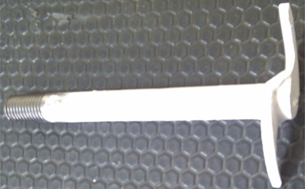
BN coated specially designed attributor. BN: Boron Nitride.
Samples taken from cast parts were exposed to grinding and polishing processes before microstructure investigations under scanning optical microscope. A Clemex image analyzer equipped with a Nikon Eclipse L150A optical microscope (Nikon Metrology Inc. in Japan), and a Jeol JSM-5410 model SEM (JEOL Ltd. in Japan) were used. SiC microstructures (5–15 wt%) of the Al 7075 matrix alloy are given in Figure 4. From Figure 4, it is observed that SiC particles are black color and angular shape in the Al 7075 alloy. SEM images of polished surfaces of composite reinforced with 10 wt% SiC particles are shown in Figure 5. These SEM indicates that hard SiC particles are uniformly distributed in the Al 7075 alloy. It is seen that a strong interface bond has between SiC particles and the Al 7075 alloy.
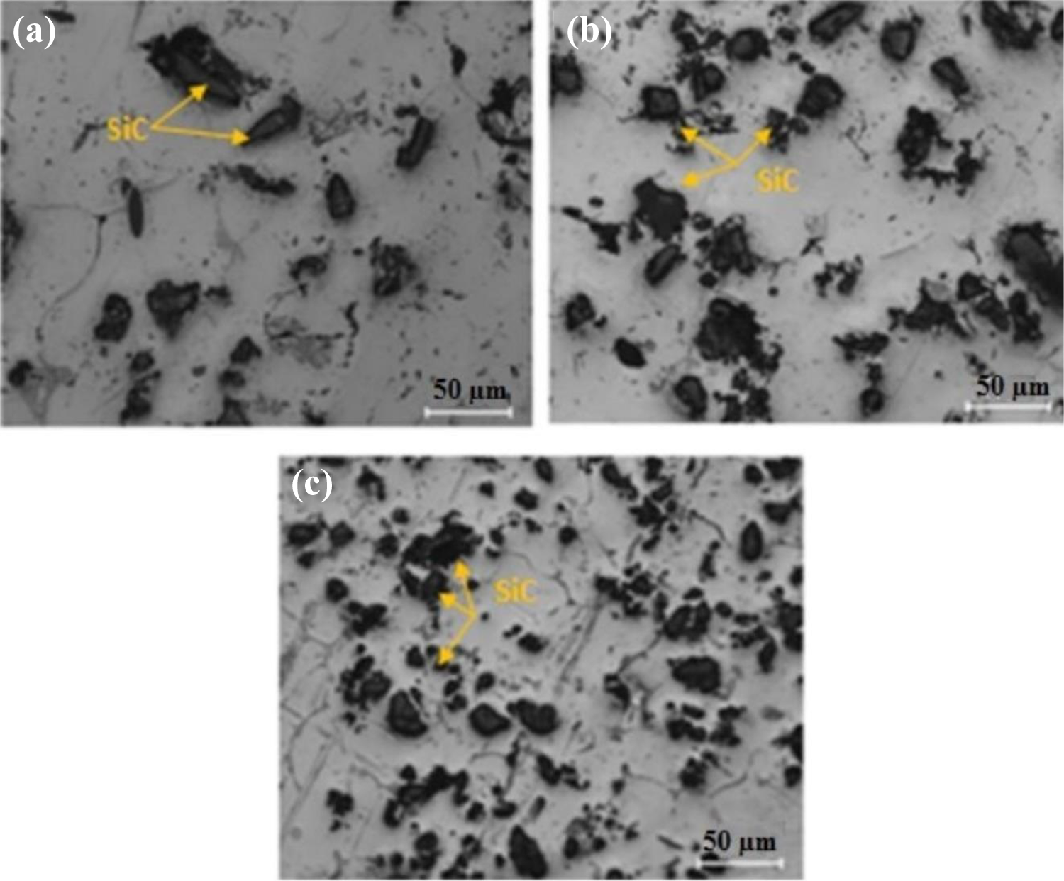
Optical images of the microstructures of stir casting SiCp/Al 7075 composites; (a) 5 wt%; (b) 10 wt%; and (c) 15 wt%. SiC: silicon carbide.
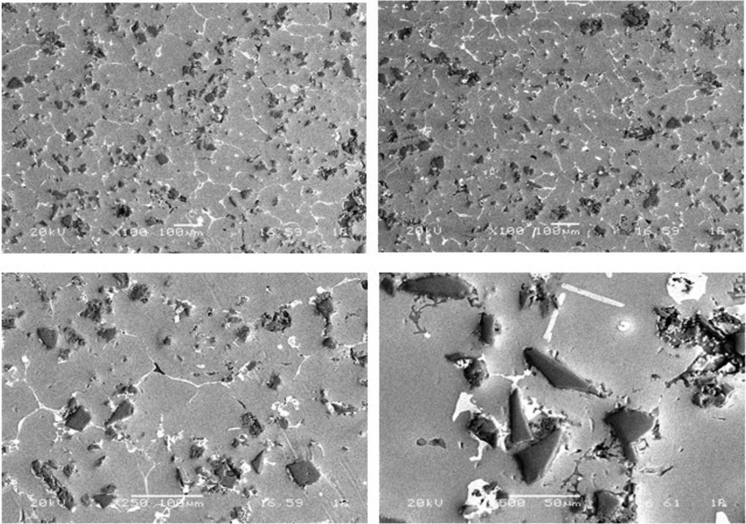
SEM images of the polished surface of composite reinforced with 10% SiC particle. SEM: scanning electron microscope; SiC: silicon carbide.
Hardness values were determined according to ASTM D 2240. 34 Hardness measurements of the Al 7075 matrix alloy and SiCp/Al 7075 composite materials were performed by using the AFFRI model tester (AFFRI Inc. in USA). Brinell hardness tests were measured at 10 kg load. The maximum hardness value was obtained as 91 HB for composite with reinforced 15 wt% SiC particle (Figure 6).

Hardness values of test samples.
Drilling tests
The drilling tests were conducted by twist drill of the MMC with reinforced SiCp test specimens in cylindrical form on a HAAS TM1 Model three-axis CNC milling center (Haas Automation, Inc - CNC Machine Tools in USA), with a 5.6 kW drive motor and 4000 r/min maximum spindle speed. The height and diameter of workpiece specimens were 20 mm and 30 mm, respectively. The drilling tests were performed by using coolant in cutting processes. Drills with two different cutting tool materials such as HSS and HSS coated with TiN were used in the drilling tests. Drills had a diameter of 10 mm, a point angle of 118o, and a helix angle of 30o. Test drills are shown in Figure 7. Experiments were performed various cutting conditions with cutting speed such as 15, 20, and 25 m/min, respectively, and feed rate such as 0.05, 0.10, and 0.15 mm/rev, respectively. A total of 72-hole drilling experiments were made using two different drills. Typical photography of some drilled holes is shown in Figure 8.

Test drills.

Photography of some drilled holes.
Surface roughness measuring instrument
The surface quality of the drilled holes is one of the most important critics in structural assembly. The arithmetical mean deviation of the assessed profile (Ra ) is used intensively in manufacturing applications. Therefore, Ra is preferred in this study. Ra can be calculated by using the following equation:

where L is the sampling length used for measurement and Z is the ordinate of the profile curve of the drilled surface. A MarSurf VD140 Profilometer Model (Mahr Metrology in Germany) with cutoff length 0.8 mm was used at the evaluation stage of the surface roughness of drilled holes. Surface roughness measurements were made at four different areas of each hole surface.
Results and discussion
Effect of feed rate
The surface roughness value was affected by changing the operating conditions such as the feed rate and cutting velocity. The feed rate was a very strong influence on the surface quality of the drilled hole. The results of the experiment indicated that surface roughness value deteriorated with increasing feed rate as shown in Figures 9 and 10. As expected, the best surface roughness value was obtained drilling conditions with low feed rate (0.05 mm/rev) and also worse surface quality occurred with an increase of feed rate for both composite materials and matrix material. This situation was expressed with increasing temperature in the cutting zone. The temperature increased with a higher feed rate and reduced the bonding strength between the reinforcement phase and matrix. Due to the softening of the matrix materials around the SiC particles, they were pulled out of the machined surface. Also, the contact duration between the drill and the composite decreased with increasing feed and hence reduced the improving effect on the machined surface. This result is suitable with results reported in previous studies in the literature. 25,27,29,35 –39

Effect of feed rate on surface roughness for HSS drills cutting velocity: (a) 15 m/min, (b) 20 m/min, and (c) 25 m/min. HSS: high-speed steel.

Effect of feed rate on surface roughness for HSS + TiN drills cutting velocity: (a) 15 m/min, (b) 20 m/min, and (c) 25 m/min. HSS: high-speed steel; TiN: titanium nitride.
Also, surface roughness values increased with increasing feed rate due to the more serious buildup edge (BUE) forms on the cutting edge of the drill with an increase in the feed rate. 25
Basavarajappa et al. 27 investigated drill materials and operating conditions on surface roughness values of drilled holes of aluminum composite and hybrid composite reinforced with SiC and graphite particles. They found that the surface quality of the drilled holes increased with increasing the feed rate.
Taskesen and Kutukde 40 found results with complete disagreement. They statically investigated drilling of AMCs reinforced with B4C particle and optimum drilling conditions obtained with ANOVA method. Besides, they observed that less cutting tool wear occurred with increasing the feed rate and obtained better surface roughness. Similar findings were obtained by Tosun and Muratoglu. 28
Davim and Baptista reported that surface roughness of A356/20/SiCp-T6 composite material deteriorated when the feed rate was increased. 41
Effect of cutting velocity
Figures 11 and 12 showed the variation of measured surface roughness as function cutting velocity. It is apparent from Figures 11 and 12 that the surface roughness values decreased with increasing cutting speed. This behavior can be explained by small SiC particles. Trapped small SiC particles between the flank surface of drill and composite materials have to hone and/or burnishing effect on the drilled surface by rubbing action. This result is observed by Ahamed et al. 42

Effect of cutting velocity on surface roughness for HSS drills feed rate: (a) 0.05 mm/rev, (b) 0.10 mm/rev, and (c) 0.15 mm/rev. HSS: high-speed steel.

Effect of cutting velocity on surface roughness for HSS + TiN drills feed rate: (a) 0.05 mm/rev, (b) 0.10 mm/rev, and (c) 0.15 mm/rev. HSS: high-speed steel; TiN: titanium nitride.
Furthermore, the surface quality of the drilled hole improved with increasing the cutting speed. As the cutting force was increased in drilling operation at high cutting velocity, composite material surface smoothly machined and obtained the best quality surface of the drilled hole. This result is in agreement with other researchers. 25,26,37
Kilickap et al. 39 investigated the effects of operating parameters such as feed rate, cutting velocity, and depth of cut on surface roughness, and tool wear of aluminum composite materials reinforced with SiC particle. They reported that the best surface roughness is produced at higher cutting velocity (150 m/min) and lower feed rate (0.1 mm/rev) cutting conditions.
Ramulu et al. 25 who investigated machinability of (Al2O3)p/6061composite materials by using three different drill materials such as HSS, carbide, and PCD. They observed that the best surface quality occurred at optimum operating conditions including the lowest feed rate and the highest cutting velocity.
Davim studied the effect of feed rate, cutting velocity, cutting time on tool wear, cutting pressure, and surface roughness in drilling A356/20/SiCp-T6 composite material. He reported that cutting velocity great (41%) influence on surface roughness. 43
Effect of reinforcement ratio
Figure 13 shows the variation of the surface roughness effect as a function of the reinforcement ratio for different cutting speeds. It was reported that matrix alloy better surface quality exhibits than composites materials for all cutting velocity. This behavior increasing reinforcement in the composite material can be attributed to worse surface quality. Different situations might take place on the machined fresh surface after drilling. Firstly, the hard SiC particles trapped on the fresh surface. Secondly, these particles were pulled out on the surface. Lastly, particles were broken and were pressured on the surface by cutting tool. These three different situations were a very strongly effect of surface roughness and/or quality of MMCs. These results are similar to reported by many investigators. 25, 42, 44

Effect of reinforcement ratio on surface roughness for HSS drills cutting velocity: 15 m/min, feed rate: (a) 0.05 mm/rev (b) 0.10 mm/rev and (c) 0.15 mm/rev. HSS: high-speed steel.
Kannan and Kishawy reported that voids and pit holes have occurred in composite materials with the increasing reinforcement ratios and this situation had a harmful effect on the machined surface. 45
Pramanik et al. 36 experimentally studied the effects of the hard ceramic particles on the machining performance of MMCs. They reported that ceramic reinforcements play a significant role in machining performance of the MMCs. However, Rajmohan and Palanikumar 37 reported that the surface roughness was decreased with the increase of SiC particles in the composite materials. They attributed to the increase of brittleness and BUE no existence on the flank surface of a drill.
Effect of cutting tool
Figures 11 and 12 show the effects of cutting tool materials on the roughness of surface of MMCs in machining operations. It is clear from these figures that for all the cutting conditions, TiN-coated HSS drills better performance exhibit than HSS drills. This behavior can be attributed to an increase of tool hardness. The harmful effect of hard- and abrasive-reinforced particles is more effective on the machining performance of HSS drills compared with TiN-coated HSS drills. Therefore, it is suggested that TiN-coated drills with lower tool wear can be used to obtain lower surface roughness. The experimental study of Basavarajapp et al. 27 reports similar findings to that of this study that hard coating existence over the surface of the drill improving influences on the surface roughness of hybrid composite material.
Secondly, this is due probably to the hard TiN-coating existence over the flank surface of the drill, and this improving effect reduced BUE formation on the flank surface. 46,47 Due to this feature, Tosun and Muratoglu recommended TiN-coated HSS drill in drilling SiC-reinforced Al2124 composite material. 48
In addition, it can be said that the dislodged small hard particles at the interface between the flank face of the cutting tools and composite materials cause burnishing and honing effect on the machined surface. 39 Similar observation is reported by Muniaraj et al. 22
Chip formation
Mechanical characteristics of the matrix alloy are affected by reinforcement phases. When the hard SiC particles are added into the matrix alloy, hardness values of the matrix alloy increase. This situation will cause large plastic shear which leads to chip formation. This phenomenon is reported by Hoecheng et al. and Shoba et al. 49, 50 Finally, it can be suggested that the chip formation increased with increasing the percentage of SiC particles.
The chips carefully are collected to examine chip shape and/or type in drilling operations. The chip type is affected by machining parameters including material type, cutting velocity, feed rate, etc.
Figures 14 and 15 are shown that the chip types are obtained as a function of the feed rate and cutting velocity in drilling operations for two different drills. It is clear from Figures 14 and 15 that the rate of SiC in the composites has a very influential on the chip size. Also, it is found that the chip size reduced with the increasing rate of hard SiC particles in composites. The feed rate has a second important influence on the chip size. Figures 14 and 15 showed that the chip size increases with increasing the feed rate for all materials. The chip size at the lower feed rate is very small compared to at the higher feed rate.

Chips obtained using HSS drills in drilling. HSS: high-speed steel.

Chips obtained using HSS + TiN drills in drilling. HSS: high-speed steel; TiN: titanium nitride.
Conclusions
The following conclusions can be drawn from this investigation on drilling of SiCp/Al 7075 composite materials using three different drills at different cutting parameters: Cutting parameters such as the feed rate and the cutting velocity had a crucial influence on the surface roughness. The surface roughness values increased with increasing the feed rate and decreased with increasing the cutting velocity. The surface roughness values increased with the amount of SiC particles. The best quality of the hole surface was obtained at the highest cutting velocity (25 m/min) and at the lowest feed rate (0.05 mm/rev) in the drilling operation. TiN-coated HSS drills better performance exhibits than HSS drills according to the surface roughness The chip size and/or curvature increased with increasing the feed rate parameter. The presence of SiC particles into the composites tends to increase powder like chips.
Footnotes
Declaration of conflicting interests
The author(s) declared no potential conflicts of interest with respect to the research, authorship, and/or publication of this article.
Funding
The author(s) received no financial support for the research, authorship, and/or publication of this article.