
Abstract
Polyetherimide Composite (PEC) is among the least dense and most compliant materials which possesses the properties of high heat resistance, durability, resistant to wear and corrosion as well as better tribological characteristics. These outstanding properties lead to its diverse applications in automobiles, aerospace, robots, sports equipment. PEC is machined by the conventional machining techniques like cutting, drilling, power hacksaw etc. Some of the limitations observed in conventional machining of these such as tool jamming, damage to surface topology, and fibres. To overcome the aforesaid limitations, in this work attempts to introduce rotary ultrasonic drilling (RUD) as viable option for machining of PEC. This work carries out the investigational study of input control factors on material removal rate (MRR) and surface roughness (SR). The outcomes of the study reveal that the with right selection of drilling control factors, better quality holes with superior topography as compared to conventional drilling, good surface finish, small exit chip sizes, low overcut errors are obtained. Interacting levels of higher spindle speed and a lower feed rate generated better surface characteristics. While drilling with the RUD as compared to normal drilling, there is a drop of 59.01 % at 550 rpm and 60 .9 % at 2550 rpm in SR.
Keywords
Introduction
Composite materials using polymer as matrix and reinforced with carbon fiber are called carbon fiber reinforced polymer composite (CFRP). 1 The interphase region is 3-dimensional with specific qualities between carbon fibers and polymers. The boundary between these constituents is considered a 2-dimensional structure. In CFRP composites strong carbon fibers have been covered with a weak plastic matrix.2,3 These have been reported to possess improved properties of greater toughness, strength, improved fatigue, wear and corrosion resistance, better vibration damping capacity and low friction coefficient.4–12 Due to these improved characteristics of CFRP composites, these are captivating for a variety of operations and subsequent applications.13,14 Different form of fabrications including spacecraft, aircraft, automobiles, bridges, and luxury goods are formed from CFRP composites. These composites are directly used in manufacturing of engine blades, robot arms, pressure vessels, power transmission shafts, machine spindles and chemical containers.
Amongst all CFRP composites, polyetherimide composites (PEC) are gaining an edge in engineering applications owing to its incomparable and superior properties. PEC is a high strength material which is not effectively machined by aforesaid traditional mechanical processes.9,11 Currently, it has diverse applications in industries viz. aviation, automobile, sports equipment, and other industrial applications such as wind turbine, fuel cell, offshore, deep sea drilling platform, turbo machinery, compressed gas transportation containers due to its improved properties of self-lubrication, hot hardness, high conductivity, wear resistance, static and electronic shielding etc. PEC has been drilled using RUD successfully. It can be a cost-effective way to drill PEC. RUD is a hybrid non-conventional machining process that augment operation of conventional USM with diamond grinding by using a tool which is permeated with abrasives particles.15–21 Drilling of composite RUD is the best non-conventional machining process.22–25 Past studies revealed that RUD has emerged as a more like an up-scaled version of ultrasonic drilling process.26,27
In contrast to ultrasonic machining, RUD employs a core drill which is permeated with diamond abrasives, is given vibratory motion and simultaneously approaches the workpiece in with a succession of pulses.28,29 The coolant pumped in between tool workpiece interface, clears the region from the chips emanating as a result of drilling as well as protects the tool assembly from overheating. 30 Ning et al. 31 investigated on RUM of CFRP and correlated it with grinding. RUM has been emerged to be superior to grinding from various perspectives. With increment in tool speed, reduction in cutting speed, SR and torque were observed for both RUM and grinding. But these effects were more pronounced for RUM. With increase in tool rotational speed, MRR increased for grinding but for RUM, it initially increased but start decreasing with further increase in tool rotational speed.
Kumaran et al. 32 conducted their studied on CFRP using RUM. This study was different from other studies as a cryogenic environment was maintained around the workpiece they concluded that burrs can be reduced and surface texture can be improved using cryogenic. Alternately, a high thrust force was also recorded, which was thought to be due to improvement in thermo-mechanical characteristics of CFRP composite. Ning et al. 33 focused on the RUD of CFRP composites. In this study, single-grain diamond scratching experiments with and without vibration were carried out to explore the material removal mechanism during RUD of the work-piece. The obtained results indicated an efficient material removal mechanism and generation of better hole quality in machining of work-piece composites. Singh et al. 34 conducted broad audit of RUM. It was found in the study that mechanism behind removal of material in RUM process included hammering, extraction, and abrasion phenomena leading to material extraction. In comparison with conventional USM and grinding, RUM yielded better results in terms of productivity and accuracy aspects in machining. Singh et al. 35 examined the machining characteristics of alumina ceramics using RUM. Trials were conducted to explore the influence of control factors on MRR and CS, as well as to investigate the surface microstructures of machined workpieces (alumina). Tool feed rate emerged as the chief influencing parameter in RUM.
Churi et al. 36 assessed the effect of machining input factors in RUM of Ti alloys. Authors concentrated his study on exploration of the effects of three factors viz. spindle speed, feed rate, and ultrasonic power on different performance measures of force, MRR, and SR in machining. Study yielded that spindle speed affects cutting power and SR, but not MRR. CF and SR were significantly influenced by ultrasonic power, where as MRR remained unaffected. Wang et al. 37 experimented on CFRP composite for the pantograph strip and Gangineni et al. 38 conducted the experimental trials on CFRP composites at elevated temperatures.
A comprehensive study of drilling CFRP tubes and comparison with CFRP plates was published by Morkavuk et al. 39 According to experimental results, composite plates generally generate more force and damage when drilled than tubes, which makes them more difficult to machine. The borehole surface quality was found to be superior in the plate as opposed to the tubes, but more dust chips were formed. Morkavuk et al. 40 investigated the impact of different surface curvatures on drilling machinability. In general, the experiments showed that drilling flat surfaces results in the greatest thrust force and damage, while drilling concave surfaces causes the least. Furthermore, the concave curved surface produced substantially better holes when the cutting parameters were the same as those on the flat surface. Atif et al. 41 attempted UAD of GLARE fibre metal laminates. Based on their study, the authors concluded that drilling holes in workpiece using higher cutting factors with outstanding hole quality would increase efficiency and reduce costs. Betgül et al. 42 Drilling machinability of CFRP was investigated by investigating the thickness of the support plate. It was found that the thrust force increased as the thickness of the support plate increased at low spindle speeds, but it did not have a significant effect on thrust force at high spindle speeds. Morkavuk et al. 43 reported the effects of drilling damage and hole quality on the tensile and fatigue behavior of CFRP tubes. The research aimed to examine the impact of drilling-induced defects and hole precision on the tensile and fatigue properties of filament-wound and roll-wrapped composite tubes. In addition, it was seen that different drilling situations influence filament-wound tube mechanical performance, but it was observed that manufacturing defects dominate roll-wrapped tube mechanical behaviour, so drilling situations did not significantly influence the mechanical behaviour. Giasin et al. 44 analysed the performance of conventional and UAD of GLARE fibre metal. The utilization of Ultrasonic Assisted Drilling (UAD) led to a notable decrease in thrust force by as much as 65%, with no impact on SR metrics Ra and Rz based on the drilling method employed. Scanning Electron Microscope (SEM) examination revealed irregular and fuzzy surfaces in glass fibre layers within holes drilled using UAD, attributed to the longitudinal vibration of the tool. Recently Baraheni et al. 45 investigated the effect of ultrasonic assisted drilling on polymer. They conclude that machinability can be improved with ultrasonic vibrations on drill tool.
In this experimental investigation, RUD is employed to accomplish drilling in PEC for the applications in automobiles, aerospace, robots, sports equipment. The feasibility of machining PEC using RUD is investigated experimentally. SR and MRR are taken as performance measures. Objectives of experimental investigation are to investigate the effect of drilling control factors on the SR & MRR as well as to develop the statistical model for predicting the SR and MRR. The impacts of drilling control factors on output responses are ascertained using data of experiments planned through factorial experimental designs.
Investigational set – up and procedures
Workpiece details
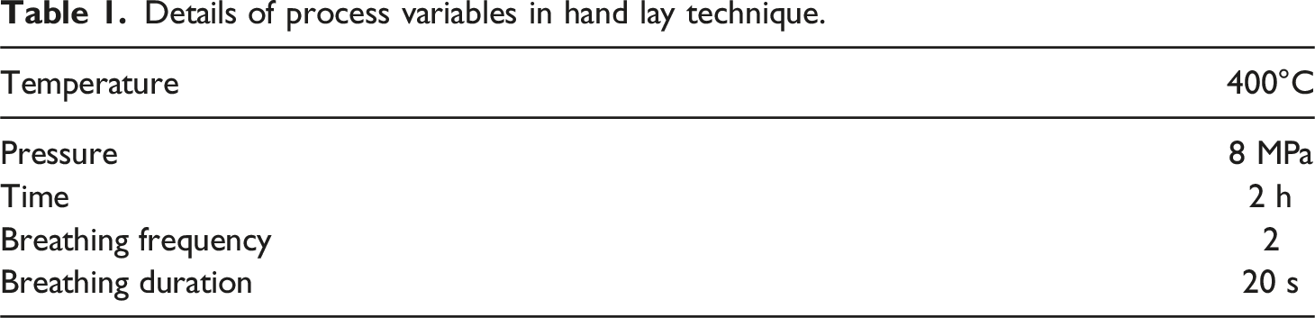
Details of process variables in hand lay technique.
Preparation of solution
The prerequisites for forming a solution are the solvent and solute components. During fabrication of composite, polyetherimide (PEI) serve as solute whereas dichloromethane (DCM) acts as solvent, which are mixed together in proportions of 1:10. Depending upon the size requirements of composite, 250g of PEI is mixed in 2.5 L of DCM. To ensure that the mixture retains the state of high viscosity liquid, the solution is kept undisturbed for 24 h in a container. However, the mixture is occasionally shaken for uniform distribution of solute and solvent components. Polyetherimide composites were prepared by 24 layers of carbon fabrics. The final dimension of the prepared composite was 280 mm in length, 5 mm in thickness and 215 mm in width.
Cutting of carbon fabric
The present study utilized carbon fibres of plain weave obtained in the shape of fabric roll. Since the direction of alignment of fibres in the matrix considerably influence its resulting wear properties, therefore the fabrics are cut of the required size of 12 × 12 inch parallel to the weaving direction of threads constituting the fabric. Plastic tape is applied at the edges of carbon fibres to avoid misalignment of fibre components
Dipping of fabric
A mould fabricated out of Al is used in which mixture of PEI and DCM is poured. Thereafter, carbon fibre piece was soaked in the solution. To ensure proper wetting of carbon fibre in the solution, excess mixture also poured over the carbon fibre. To ensure that there is no leakage of vapours and fumes from mould, it is closed tightly with a lid followed by proper sealing using aluminium foil.
Drying of fabric
After 12 h, carbon fabrics are withdrawn from the mould by opening the lid cautiously to avoid direct inhaling of fumes from the mould. With the continuous application of pressure exerted by weights, fabrics impregnated with solution are allowed to dry. Application of pressure ensures avoidance of any onset of bends and curls in the weave.
Compression of fabric
The aforesaid procedure is followed for 24 carbon fabric pieces and 24 such carbon fabric pieces covered with matrix are obtained. All of these pieces is placed in a preheated mould one over another in such a way that a stacked column of 24 layers of fabric is obtained. Compression moulding machine is utilized to compress the stacked column through a plug member to ensure proper adhesion between the constituting layers of fabric. Due to application of pressure of 8 MPa, the stacked columns of fabrics assume the shape of the mould. Pressure remained applied on fabrics for 2 hours to ensure proper adhesion between different layers. This completes the process of fabrication of composite and the obtained composite is withdrawn from the mould. The details of the study can be referred from Gupta et al.46–48 No deformation or compensation was observed during the preparation of the composite, as the central region of composite was chosen after sectioning and cutting of samples.
Experimentations Details
A hollow drill tool is designed and fabricated to carry out this investigation. The drill tool, is fabricated with a shank diameter (ɸ1) of 6.5 mm. Internal diameter (2.8 mm) and external diameter (4.5 mm) of the hollow tools. The diamond abrasive particles with different mesh sizes (#100, #180 #260 #340 and #420) impregnated on the tool are used for the experimentation. These abrasives particles are electroplated on the EN-31 steel hollow shank. After the fabrication of the tool, RUD assembly is fabricated which included an ultrasonic vibration transducer, hollow tools, horn, piezoelectric crystal rings, housing, and the CNC collet adaptor. It also contains nut and collet arrangement for holding the diamond-impregnated tool during RUD of CFRP composite. A special housing is built with metal on black material having two-end faces. The ultrasonic transducer is fixed at one side of the housing and the CNC collet adapter on the other side as shown in Figure 1. Fabricated setup for RUD process.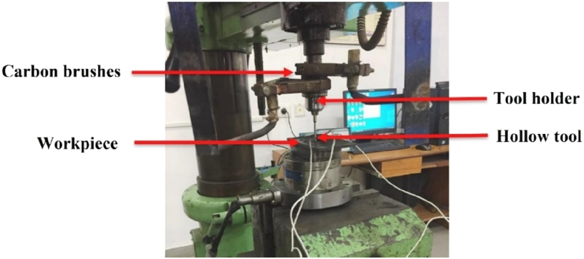
A tool holder holds the drilling tool onto the ultrasonic horn. The housing is also fitted with a pair of slip rings. A voltage signal is provided to the ultrasonic horn through carbon brushes slip rings. Using a CNC controlled tool holder, the entire assembly is mounted on a CNC vertical milling chuck. With the Piezo View software, the vibrational frequency of the designed RUD assembly with drill tools is measured. The designed RUD assembly with hollow tool has a frequency of 20,119.5 Hz which is approximately 20 kHz. Vibrational amplitudes of the designed tool are measured using a dial indicator, and could be controlled by altering the voltage. The entire assembly of tool, horn and slip rings is clamped on a computer controlled vertical milling chuck in which a tool holder is mounted.
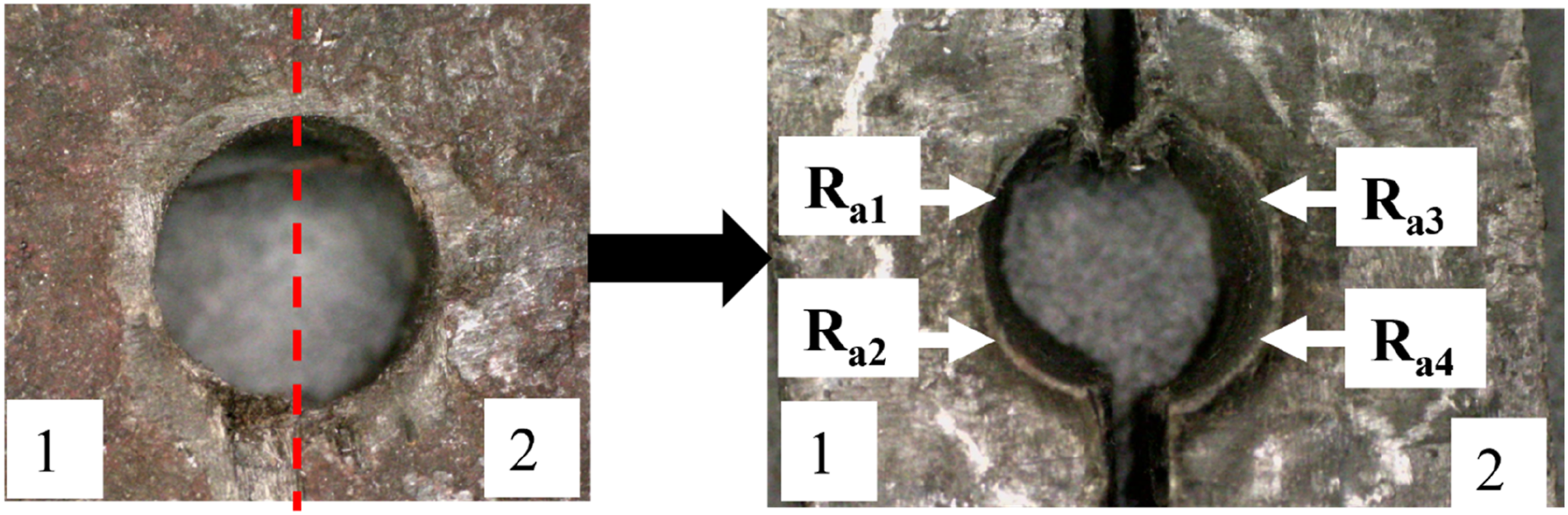
All experiments are conducted on the aforementioned setup. SR is measured using a surface roughness tester (Mitutoyo SJ400). The drilled holes are cut into two equal halves and roughness is measured on four different positions as shown Figure 2. Readings of surface roughness are replicated four times and then final average value is taken into consideration as an outcome of the process. Equation (1) is used to calculate the MRR taking into consideration diameter of the crater obtained after drilling, the marked diameter of the crater to be made and the time of engagement of drill with the composite. Schematic representation for measurement of SR.
Design of experiment (DOE) and Selection of Input Control Factors
Machining parameters with their range.
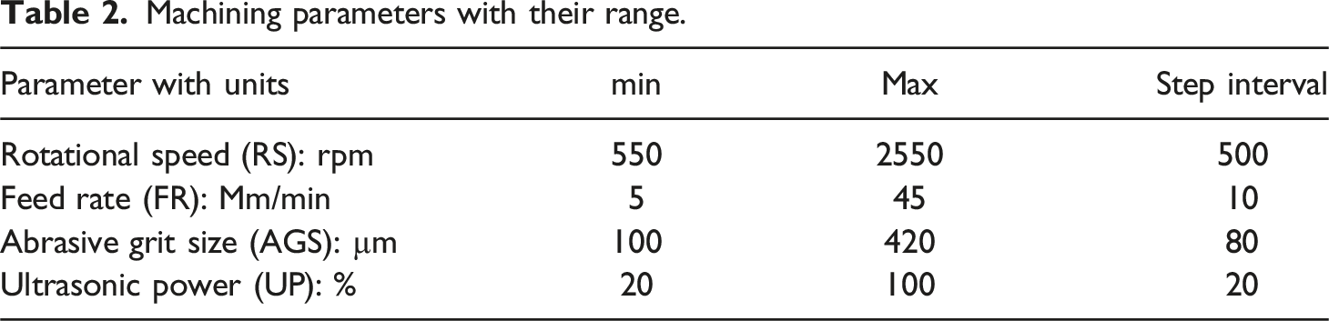
For the current study, a rotational speed of 550 to 2550 rpm is selected. The range of the variation of speed is chosen based on the literature survey49,50 of previous studies on drilling of composites and taking into account the limitation of speed of the experimental setup. Feed rate is another key factor that contributes to efficiency of drilling of composite. The effect of feed rate in the drilling force is more as compared to the drilling speed. 51 Literature indicates that delamination of composite and fractures are produced in the vicinity of drill site edge on the workpiece (composite) as feed rate is increased beyond 50 mm/min.21,52 In accordance with the previous conducted studies15,19,53–55 by various researchers in the field of drilling of composites, a feed rate between 5 and 45 mm/min was selected.
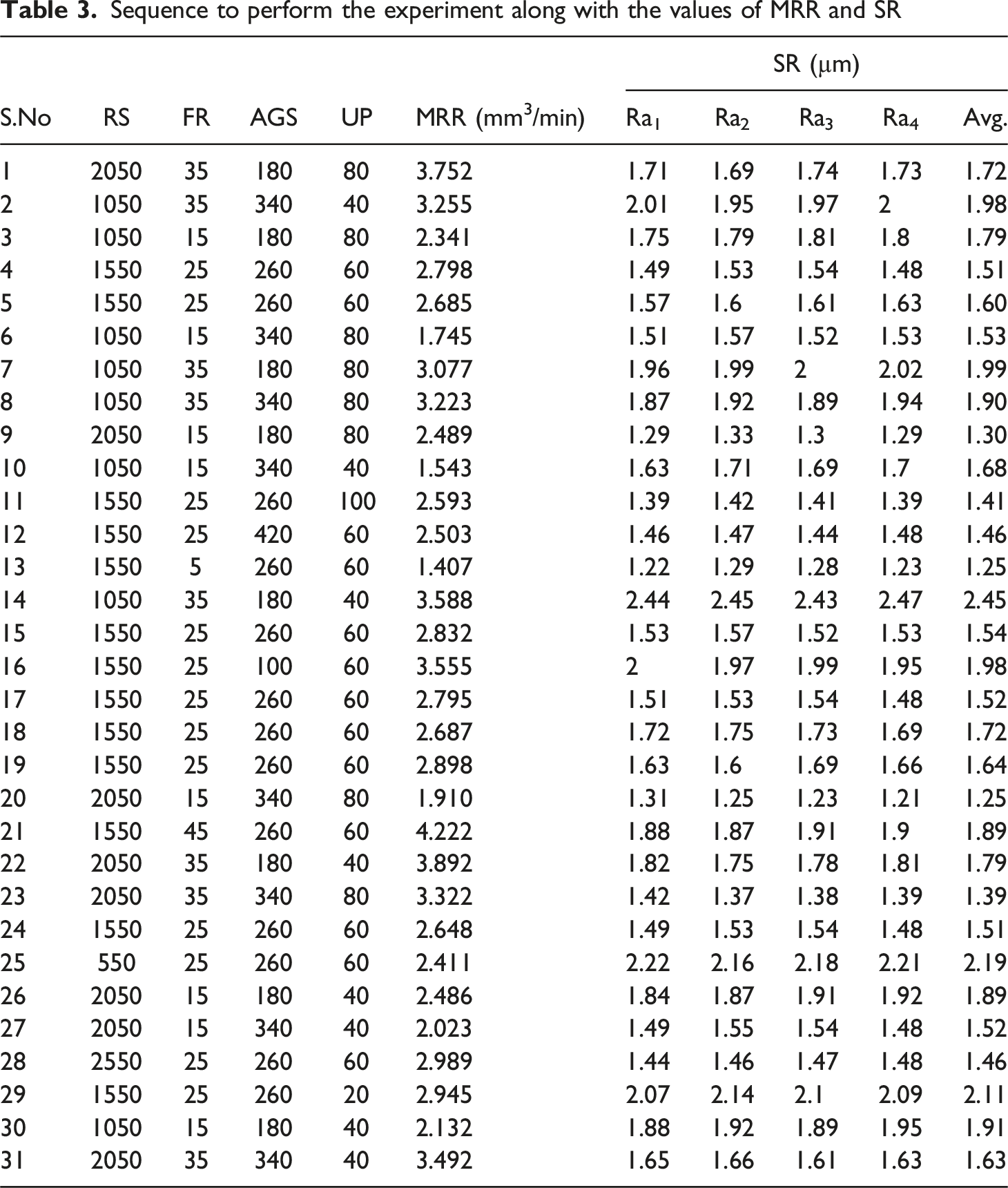
Sequence to perform the experiment along with the values of MRR and SR
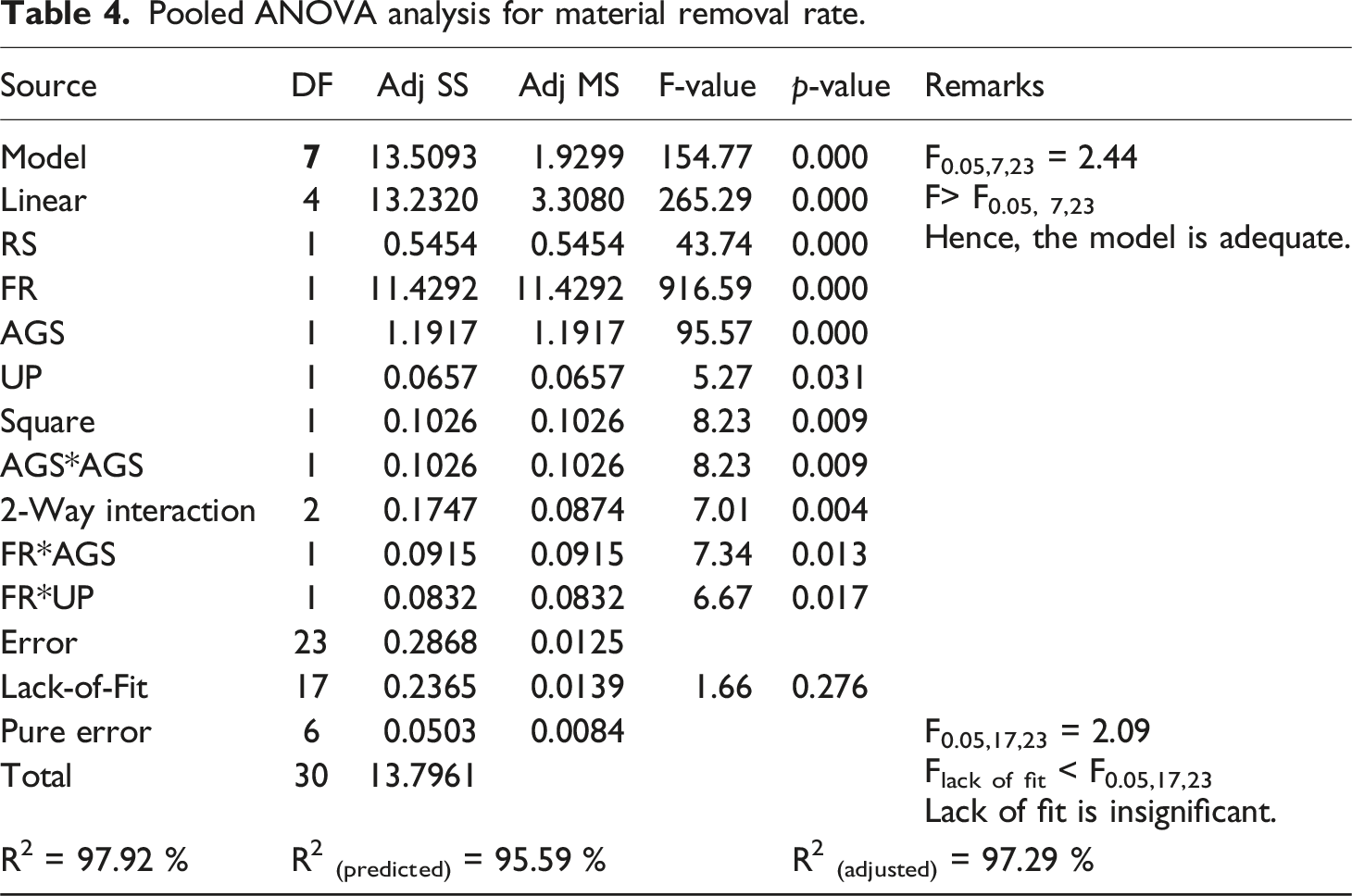
Pooled ANOVA analysis for material removal rate.
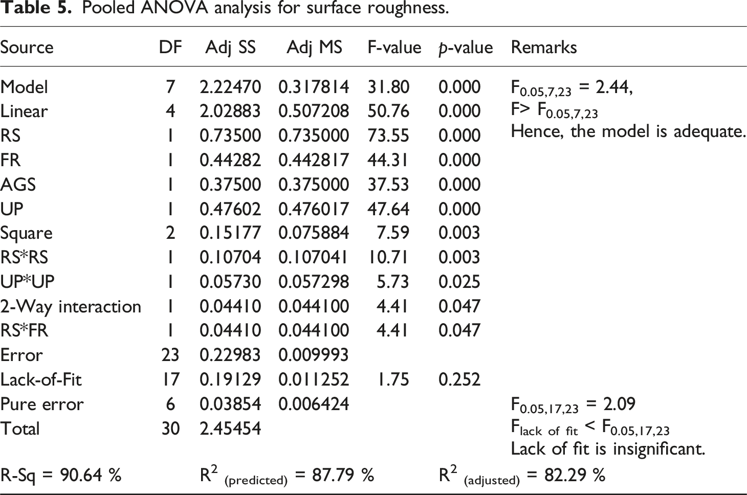
Pooled ANOVA analysis for surface roughness.
Results and discussions
The data shown in the Table 3, are examined by the traditional steps provided by response surface methodology (RSM). ANOVA is applied to assess the impact of input control factors on MRR and SR. The results of analysis as follows.
Empirical modelling of MRR and SR
The 2nd order RSM is recommended by the regression analysis for MRR and SR obtained as the results of experimentation. The MRR and average SR values obtained from the set of experiments as mentioned in Table 3 has been analysed by ANOVA. Initially, ANOVA is performed by taking into account combinations of all interaction effects and main effects. The obtained empirical models are very lengthy including non-significant terms depicting non-significant effects. These predicted empirical models were refined by employing backward elimination that removes insignificant terms having p values more than 0.05 and presented in the equations (2) and (3) for MRR and SR respectively. Corresponding ANOVA analysis are shown in Tables 4 and 5.

The adequacy and lack of fit for the presented numerical models is tested and validated using the F values from the ANOVA Tables 4 and 5. F values obtained for MRR and SR are 154.77 and 31.80, respectively. Since these F values are more than the tabulated F values provided in the distribution tables i.e. F0.05, 7, 23 = 2.44 (for MRR) and F 0.05,7,23 = 2.44 for SR; that authenticates adequacy of model fitting. Similarly, F values for lack of fit of the proposed model are 1.66 and 1.75 for MRR and SR, respectively which are less than corresponding to tabulated values of F0.05, 17, 23 = 2.09 (for MRR), F 0.05,17,23 = 2.09 (for SR), which further strengthens the adequacy of model indicating that lack of fit is insignificant. R squared values are also presented in the Tables 4 and 5 for MRR and SR respectively.
Table 4 shows that adjusted (R2) = 97.29% agree with (R2) predicted = 95.59% for MRR. The same is observed for analysis of SR (Table 5) adjusted (R2) values are closer to (R2) predicted values. This indicates a strong correlation between measured values and predicted values. These strong statistical indicators authenticate the reliability of the empirical models and hence these can reliably predict values of MRR and SR.
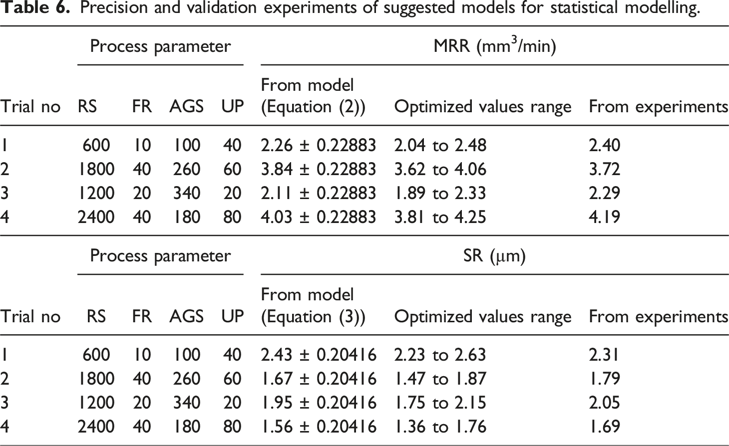
Precision and Validation of the Suggested Models
Every experimentation and subsequent regression analysis involves introduction of random errors attributed to uncontrollable factors in the environment and machinery. Therefore, it becomes imperative to quantify the accuracy of the suggested models given by equations (2) and (3) and the corresponding accuracy is calculated by equation (4).
59

Precision and validation experiments of suggested models for statistical modelling.
Effect of drilling control factors on MRR and SR
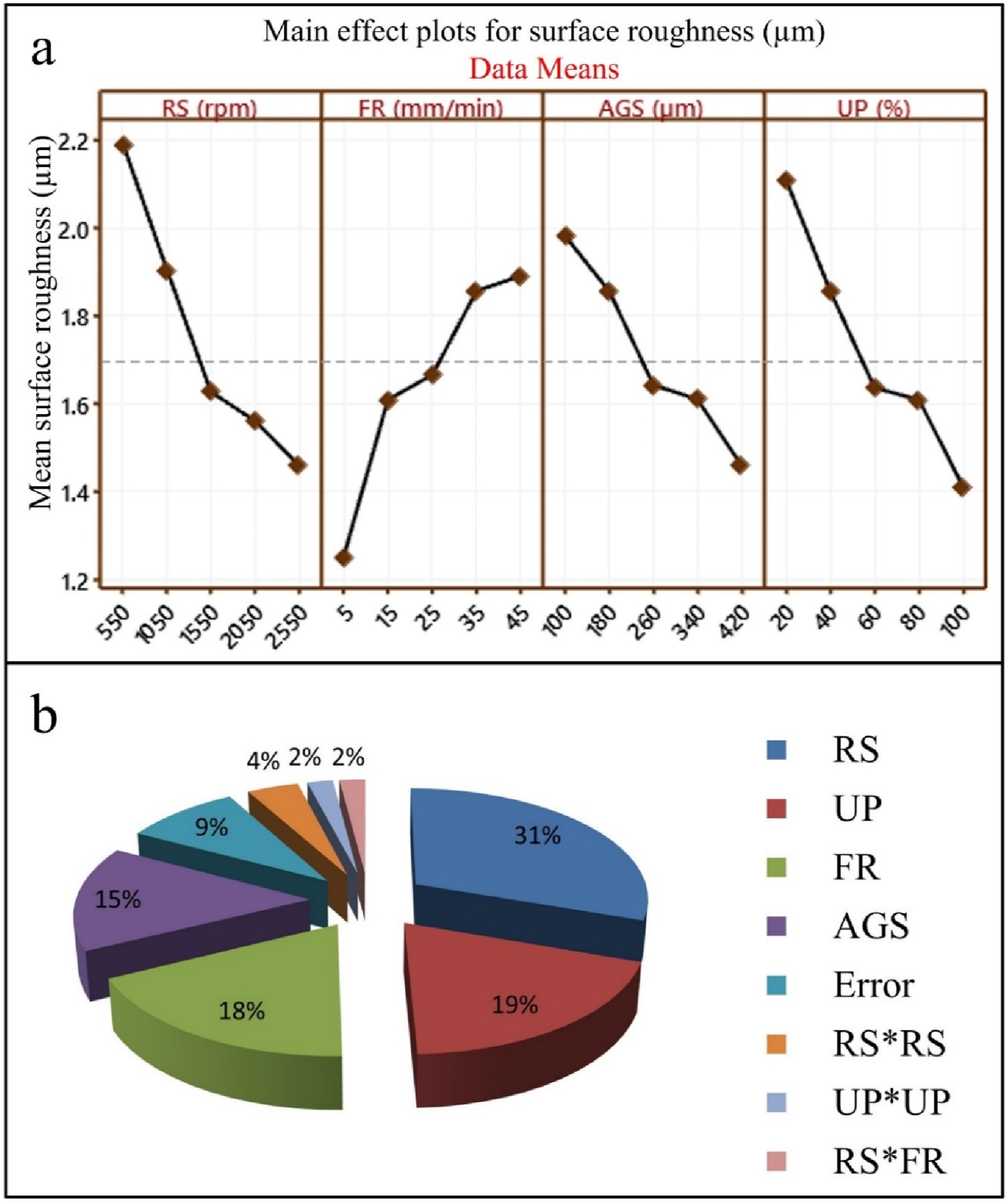
Figures (3 and 4) illustrate the plot of main effects and the contribution of control factors towards MRR and SR during drilling of PEC. The trends of MRR and SR with input control factors as derived from ANOVA, as follows: (a) Influence of drilling control factors on MRR (b) percentage contribution of these parameters on the MRR. (a) Influence of drilling control factors on SR (b) Percentage contribution of these parameters on SR.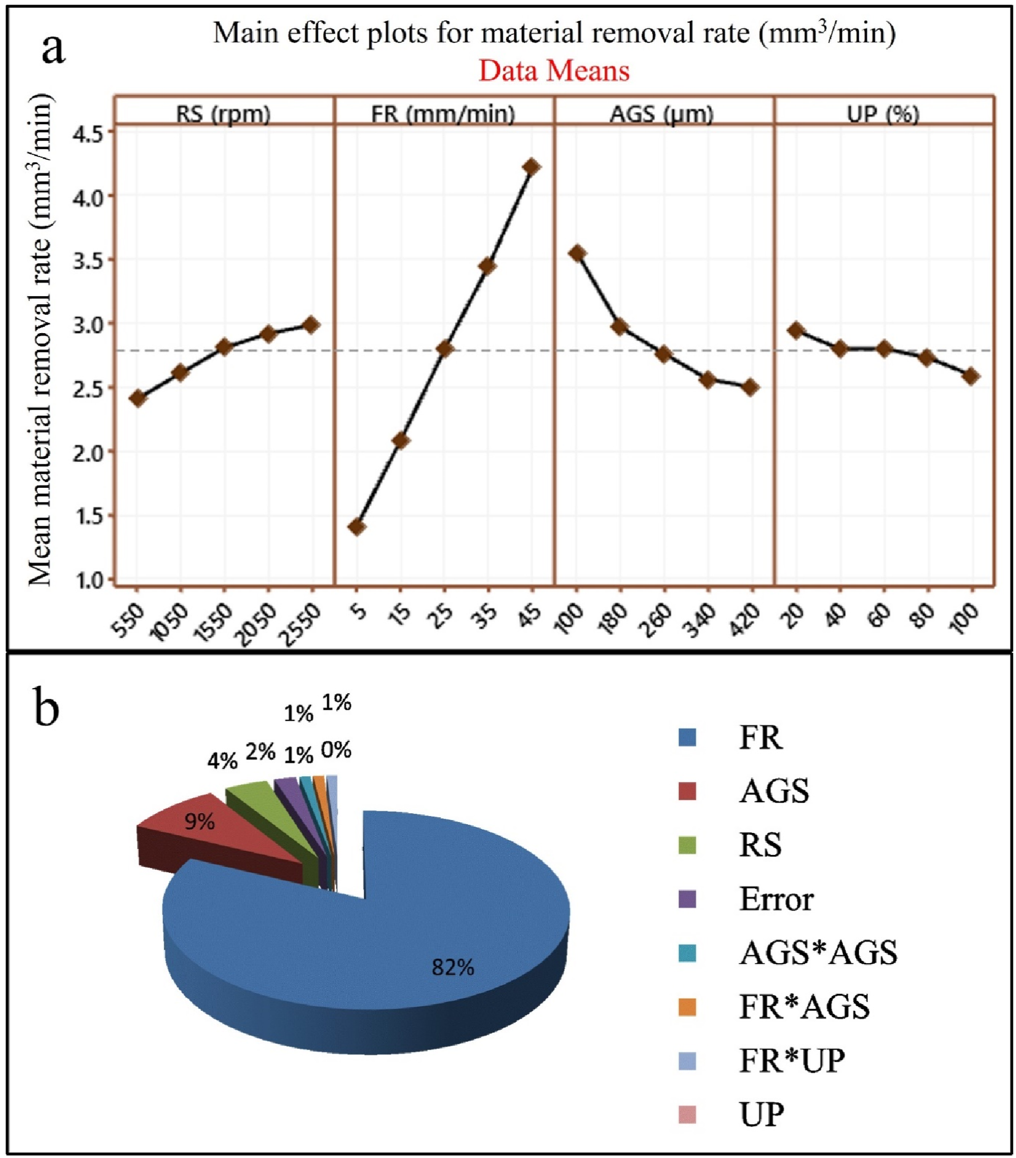
Rotational Speed vs MRR &SR
The effect of the considered control factors on MRR along with percentage contribution are shown in Figure 3(a). It is observed that the mean MRR significantly increment with an increment in the rotational speed. The plots indicate that the mean MRR is 2.41 mm3/min at 550 rpm and 2.98 mm3/min at 2550 rpm, i.e., 23.65 % increase in mean MRR has been observed with increment in rotational speed from 550 to 2550 rpm. With increasing the rotational speed, the material removal rate also increases. This is due to variations in indentation volume with variations in the rotational speed during drilling. 60 Figure 3(b) shows that rotational speed is contributing to 4% to the total MRR. In Figure 4(a) it is observed that, when rotational speed is increased, the mean SR is decreased significantly. The trends illustrate that the mean surface roughness is 2.19 µm at 550 rpm and 1.46 µm at 25 50 rpm, with 33.33 % reduction in mean SR from 550 rpm to 2550 rpm.
The time of engagement of tool with the workpiece is increased with increase in cutting speed. This leads to removal of more material from work surface in the form of tiny fragments that are dislodged from the composite by producing shallow craters on its surface. This decreases the SR. 61 These effects are in agreement with the results reported during RUM of potassium dihydrogen phosphate crystal, 62 RUBD, 49 RUM of the polymer 63 and titanium alloy. 36 Figure 4(b) demonstrates that rotational speed is the major input factor that affects the SR during RUD of the polyetherimide composites with a contribution of 31%.
Feed Rate vs MRR & SR
Figure 3(a) reveals that MRR is considerably influenced by feed rate. MRR is increased sharply with an increment in the feed rate. When the feed rate is increased,the tool movement in downward direction i.e. fed to the workpiece deep removes more material from the workpiece per unit time, thereby increasing the MRR. 36 Figure 3(b), illustrates that the feed rate emerged as major factor effecting the MRR with a percentage contribution of 82% during RUD of PEC. Figure 4(a), shows that SR is increased drastically with an increase in the feed rate. The increase in the SR is about 51.2 % for the feed increment from 5 to 45 mm/min. With increased feed rates, the tool and workpiece surface had less contact time and more cutting contact area. By decreasing total cutting time, kinematic overlap time of the abrasion path was reduced. In other words, more material is removed from the composite surface per unit time. Obviously when the contact time is less, material is dislodged from the composite in large chunks, thereby producing deep craters on composite surface. This results in higher SR. 31 These effects are matching with the results reported by the Shahabaz et al., 64 Eshetu et al. 65 in conventional drilling, Cong et al. 17 in RUD and drilling of chitosan-reinforced polypropylene composite. 66
AGS vs MRR & SR
Figure 3(a), reveals that MRR is considerably affected by AGS. As the grit size is varied 100 µm to 420 µm the reduction in MRR is noticed to be 29.53 %. The MRR decreases because the fine abrasives strike the workpiece with less momentum and remove fine particles of composite in small amount. The other reason may be due to the inherent property of the material (ductility). The amplitude gets absorbed by the material and hence the MRR is decreased with increased in the ultrasonic power. MRR trends obtained in the study are in agreement with the results reported by previous studies in ultrasonic drilling. 56 As depicted by Figure 4(a) it is found that SR is decreased with an increased in the abrsaive grit size. The decrease in the SR was noticed to be 26.26 %. This trend emerged because of the fact that with an increase in the AGS, the penetration depth of diamond abrasives reduces. So, shallow craters are indented on composite surface by dislodging fine fragments of composite material. This effectively reduces SR.
Ultrasonic Power vs MRR & SR
Figure 3(a) illustrates that MRR is effected with an increase in ultrasonic power from 20% to 40%. The effect nullifies on MRR after increment of power from beyond 40% and upto 80 %. Similar trends are observed in the explorations reported by Jiao et al. 67 Figure 4(a), reveals that SR is significantly decreased with an increase in ultrasonic power. This reduction is attributed to the concept that an increase in ultrasonic power leads to an increase in viberation amplitude. The time of engagement betweem the tool and composite is considearbly reduced with increase in the ultrasonic power. Owing to reduced friction coefficient between the PEC and diamond tool, reduced surface roughness is witnessed. These effects are in accordance with the results of studies conducted by by Jiao et al. 67 and by Churi et al. 68 in RUD of alumina and silicon carbide respectively.
Interaction effect
Equations (2) and (3) illustrate that some significant interactions occurred between the machining process parameters as listed in Table 2. These significant interaction relations of the input variables on the MRR and SR have been plotted by using these equations. Figure 5, signifies the relations between the cumulative effects of AGS size and feed rate on MRR at a constant ultrasonic power of 60 % and rotational speed of 1550 rpm. It is concluded from Figure 5 that higher level of feed rate and smaller level of AGS size lead to higher MRR. At the higher feed rate, the influence of AGS on the MRR is not very significant as compared to the lower feed rate. Correlation plot of AGS and FR vs MRR (a) 3-D & (b) 2-D plot.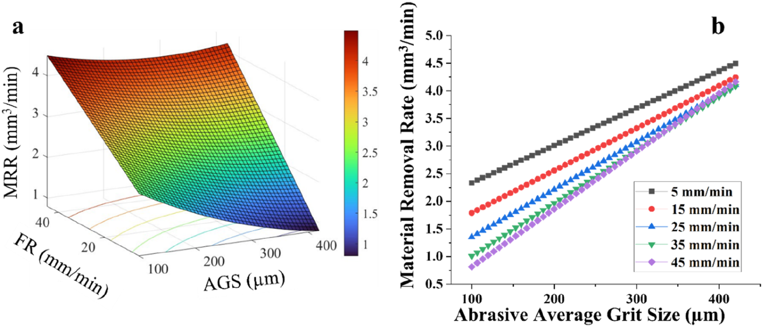
Figure 6 signifies the interaction effect i.e. cumulative influence of ultrasonic power (UP) and feed rate on MRR at a constant AGS of 260 µm and rotational speed of 1550 rpm. It is observed from Figure 6, that there is a significant fall in MRR by increment in UP and decrement in the feed rate. However, the higher value of MRR is obtained due to the cumulative effect of higher feed rate and lower UP as revealed by 2-D interaction plot. Moreover, higher MRR is also witnessed at higher UP and lower feed rate. But the magnitude of this peak level of MRR is much less as compared to MRR obtained at lower UP and higher FR. Correlation plot of UP and FR vs MRR (a) 3-D & (b) 2-D plot.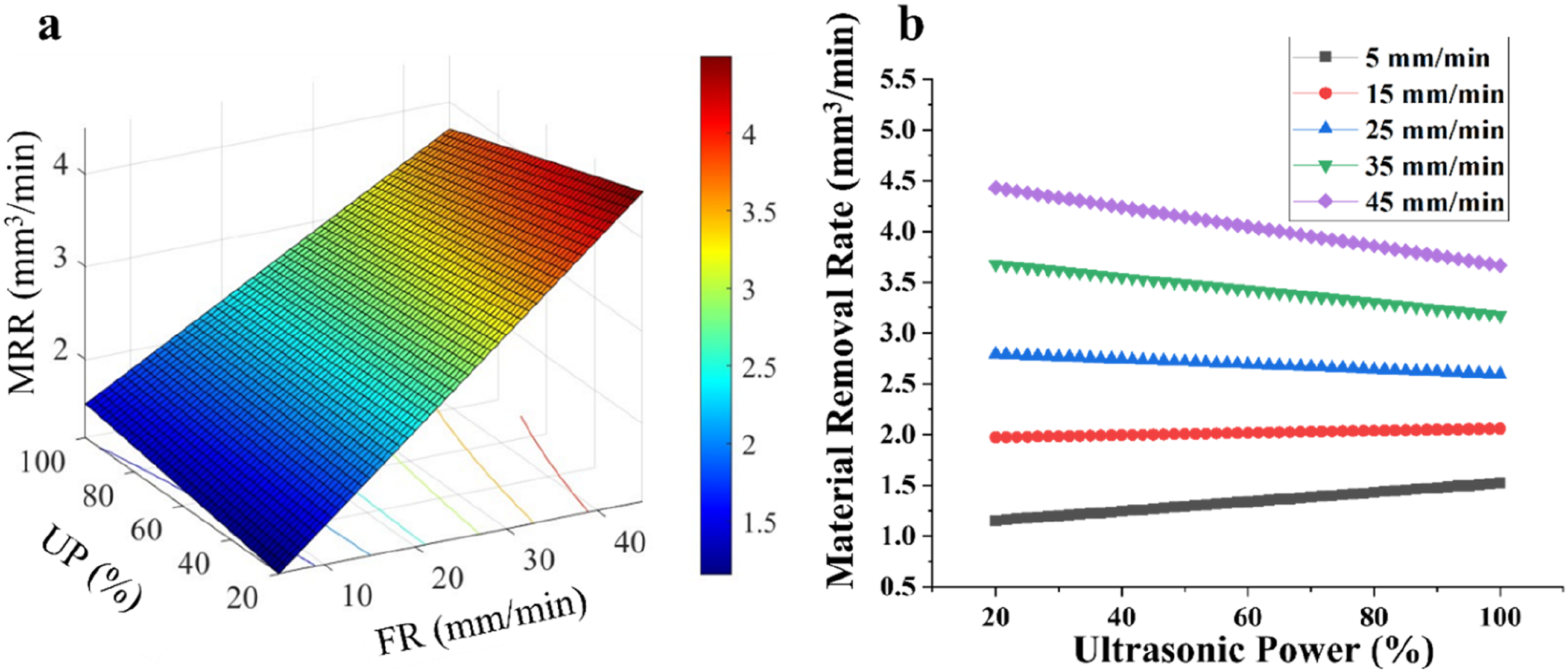
Figure 7, signifies the synergetic effect of FR and RS on SR at a constant AGS of 260 µm and ultrasonic power of 60%. From Figure 8(a), it can be inferred that SR is decreased with low feed rate and high RS, because of the aforesaid reasons discussed for change of SR with feed and RS in main effect plots. Correlation plot of RS and FR vs SR (a) 3-D & (b) 2-D plot. Chips obtained at (a) ND (b) RUD [RS = 1550 rpm, FR = 25 mm/min, AGS = 260 µm and UP = 60% (only for RUD)].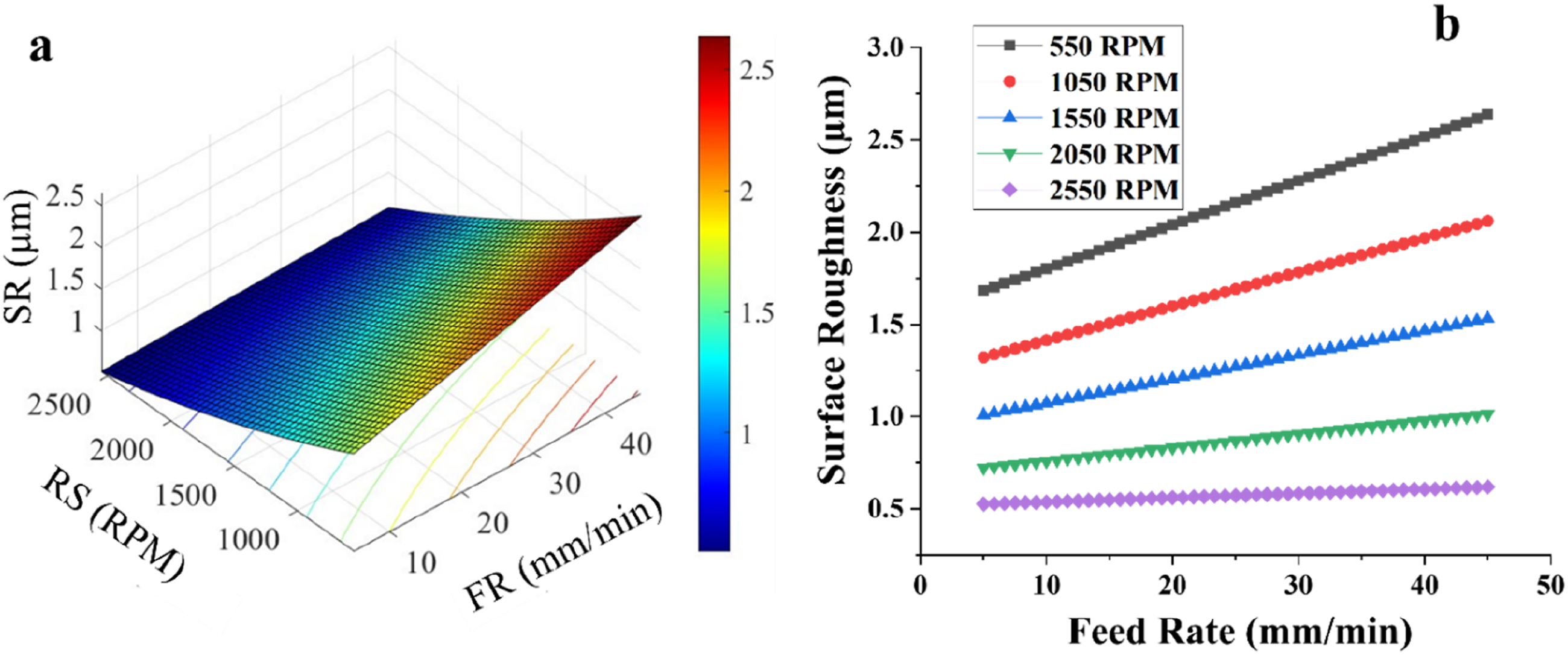
Optimization values
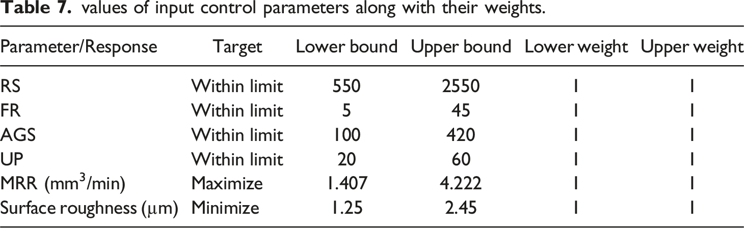
values of input control parameters along with their weights.
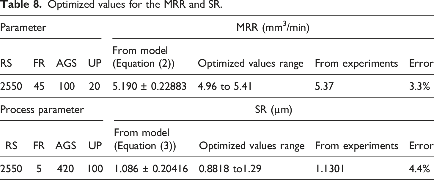
Optimized values for the MRR and SR.
Material removal mechanism in RUD and ND
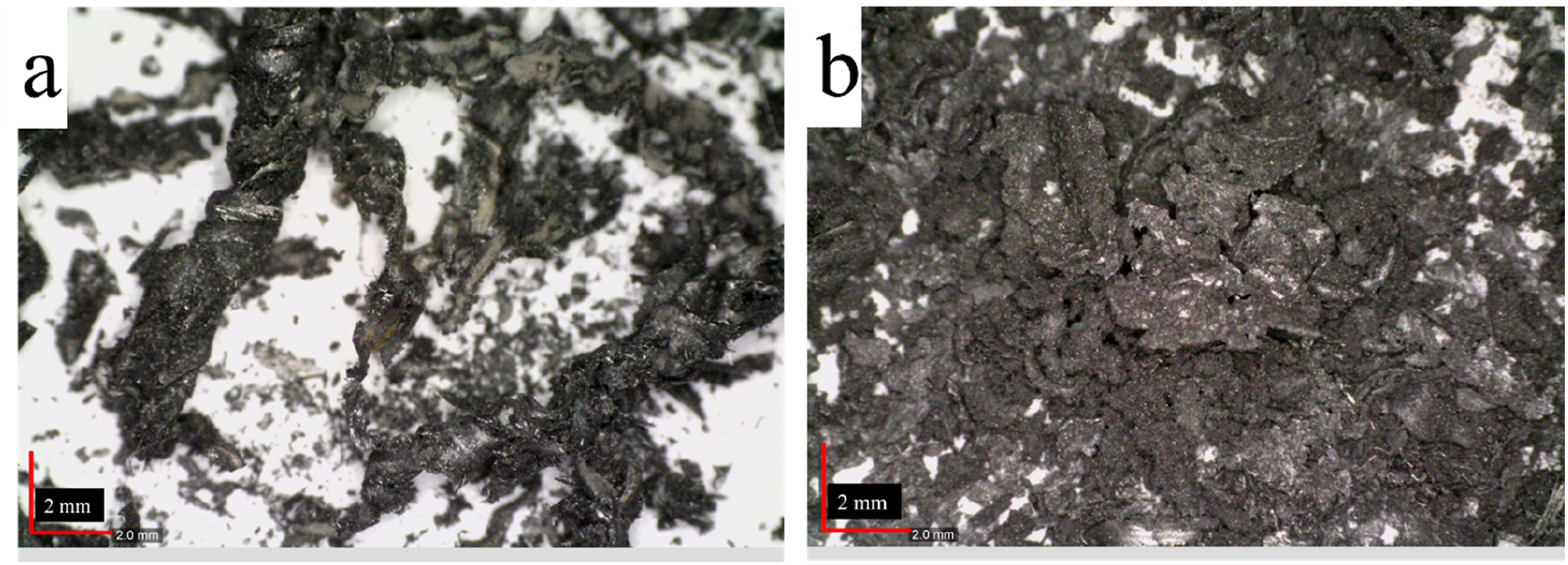
RUD is a hybrid non-traditional drilling method that employs synergistic effect of material removal mechanism of conventional diamond grinding and static USM. The level of MRR is around 60 % higher with the drilling of normal method in comparison to RUD for the same input parameters. This may be due to the fact that in case of drilling of polyetherimide composite with normal drilling the processed material is wasted in the form of chips while in case of RUD method the cylindrical rod is generated because of the hollow nature of the tool by removing fine chips. During the ND macro levels chips are formed as depicted in Figure 8(a) and Using RUD the micro sized chips are formed as depicted in Figure 8(b). Different chip morphology during drilling with ND and RUD illustrates their material removal behaviour on the CFRP composite surface.
Machined crater quality
The microscopic images of the drilled surface at the entrance position in both normal drilling (ND) and RUD after 10 and 30 drilling experiments are shown in Figure 9. RUD at the entrance position produced a much better surface quality than ND. Furthermore, in ND, the hole surface quality became much worse after 30 drilling experiments compared to 10 drilling experiments. Fractures can also be clearly seen on the surface. On the other hand, in RUD, the hole quality has a less deterioration after 30 drilling experiments as compared to 10 drilling experiments. RUD emerged as a better choice than ND for smooth drilled holes. SR in ND was higher than that in RUD under almost all conditions. This showed that normal drilling leads to generation of worse SR. Microscopic figures of drilled holes (a,b) after 10 drilling experiments, (c,d) after 30 drilling experiments w.r.t. normal drilling (a,c) and Rotary Ultrasonic Drilling respectively (b,d).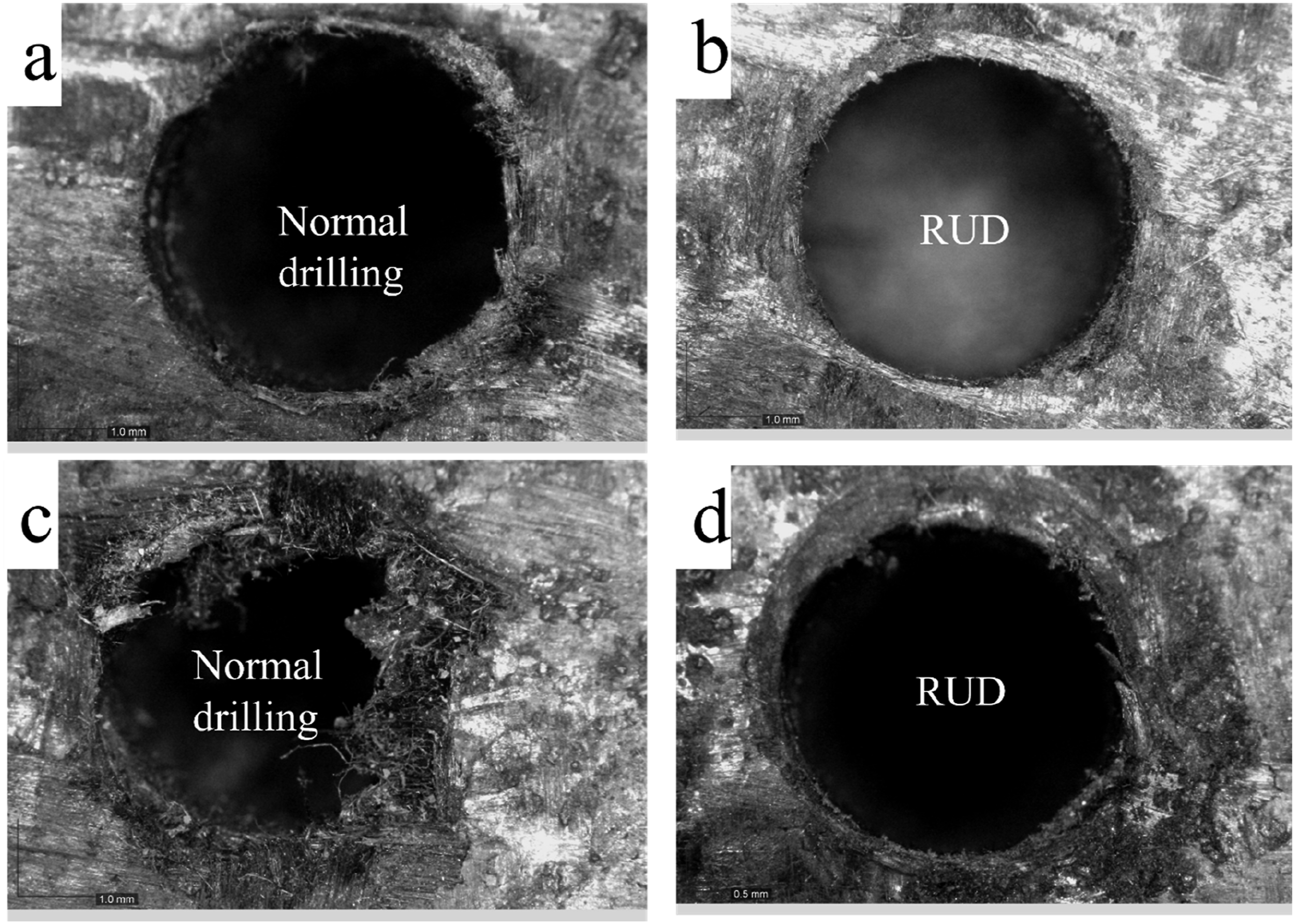
Comparison study of RUD vs ND
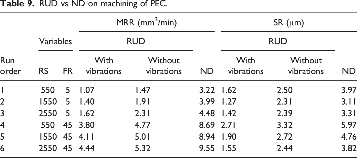
RUD vs ND on machining of PEC.
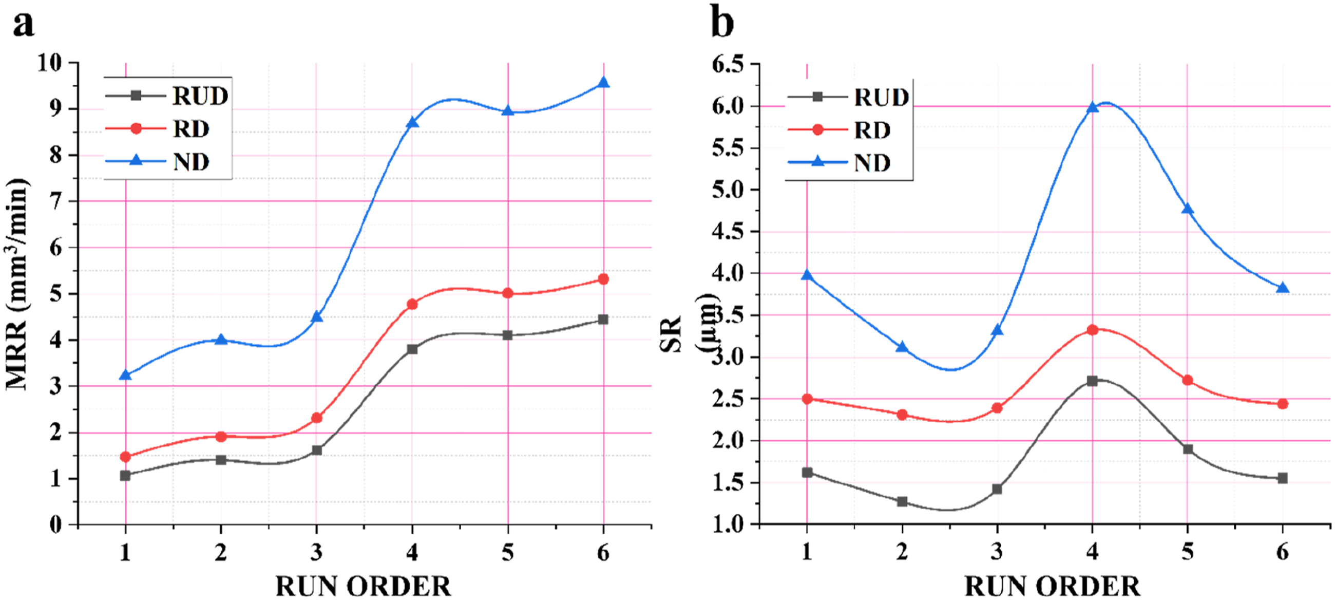
Comparison investigation of (a) MRR and (b) SR.
Conclusions
The present investigation sheds light on the influence of various drilling factors during the rotary ultrasonic drilling (RUD) of CFRP composite. The surface roughness (SR) and material removal rate (MRR) during RUD and normal drilling (ND) were monitored. Attempts have been undertaken to create predictive models for the MRR and SR in RUD based on various control variables. It is important to highlight that there is no existing literature on the RUD of polyetherimide composite materials. In summary, the key outcomes can be encapsulated as follows: • The workability of the RUD and ND methods has been successfully investigated. • Material removal rate (MRR) reduced with an increase in the average abrasive grit size and ultrasonic power. As the grit size is varied 100 µm to 420 µm, the reduction in MRR is noticed to be 29.53 %. • MRR increased with the increase in rotational speed and feedrate. The trends indicate that the mean MRR is 2.41 mm3/min at 550 rpm and 2.98 mm3/min at 2550 rpm, i.e., 23.65 % increase in mean MRR has been observed with increment in rotational speed from 550 to 2550 rpm. • Feedrate is the most influencing factor with a percentage contribution of 82% that affects the MRR. • As the value of the ultrasonic power and rotational speed increases, SR is decreased continuously. The values of SR increased almost linearly with increase in values of the feedrate. The increase in the SR is about 51.2 % for the feed increment from 5 to 45 mm/min. • The decrease in the SR is noticed to be 26.26 % as grit size varied from 100 µm to 420 µm. It is due to an increase in the abrasive grit size, the penetration depth of diamond abrasives reduces. So, material is removed from the work piece in the form of fine fragments by creating shallow craters on work piece. • Rotational speed is the major input factor that affects the SR during RUD of the polyetherimide composites with a contribution of 31%. • Statistical models for the MRR and SR are successfully developed and validated. • Interaction effects contributing to SR and MRR are also examined and discussed along with the main effects. • The hole quality produced by RUD is much better than the ND. RUD emerged as a better choice than ND for smooth drilled holes. • The hole made using a normal drilling resulted in delamination. Using RUD, no delamination was observed and no fracture was seen on the surface of the crater. • SR during ND was higher than that in RUD that leads to higher delamination and affects the surface morphology. • The level of MRR is around 60 % higher with the drilling of normal method in comparison to RUD for the same input parameters. This may be due to the fact that in case of drilling of polyetherimide composite with normal drilling the processed material is wasted in the form of chips while in case of RUD method the cylindrical rod is generated because of the hollow nature of the tool by removing fine chips.
This proposed material can be used in various industry like applications in automobiles, aerospace, robots and sports equipment etc. Machining of carbon fibre reinforced composite have a great challenge specially to drilled the hole. The limitations observed in conventional machining of these such as tool jamming, damage to surface topology, fibres and delamination. To overcome the aforesaid limitations, in this work attempts to introduce rotary ultrasonic drilling (RUD) as viable option for machining of PEC.
Footnotes
Declaration of conflicting interests
The author(s) declared no potential conflicts of interest with respect to the research, authorship, and/or publication of this article.
Funding
The author(s) received no financial support for the research, authorship, and/or publication of this article.