
Abstract
Fiber-reinforced metal matrix composites have mechanical properties highly dependent on directions, possessing high strength and fatigue resistance in fiber longitudinal direction achieved by weak interface bonding. However, the disadvantage of weak interface combination is the reduction of transversal performances. In this article, tensile and fatigue properties of carbon fiber-reinforced 5056 aluminum alloy matrix (Cf/5056Al) composite under the condition of medium-strength interface combination are carried out. The fatigue damage mechanisms of Cf/5056Al composite under tension–tension and tension–compression loads are not the same, but the fatigue life curves are close, which may be the result of the medium-strength interface combination.
Introduction
Metal matrix composites, with high specific strength and specific modulus, have a broad application prospect in aerospace, automobile, and other fields. Therefore, the in-depth study of the elastic–plastic properties, damage mechanism, and fatigue behavior of the composite will provide a reliable basis for its use.
The physical and mechanical properties of continuous fiber-reinforced metal matrix composites (FMMCs) usually show strong direction dependence. In longitudinal direction, the damage failure and tensile strength of FMMCs are controlled by strength of fiber, matrix, and interface jointly. Since the strength of fiber is usually much greater than that of matrix, the fiber bears most of the load under the longitudinal load, and the matrix mainly plays the role of transferring load between the fibers and protecting the fibers. According to the different strength of fiber/matrix interface, the continuous FMMCs can be divided into two categories: weak interface composite and strong interface composite. The strength of the former is generally controlled by the fiber strength. Due to the debonding and sliding of the interface, the stress concentration near the cracked fiber is reduced and the global stress distribution (GLS) is formed, so its longitudinal strength is relatively high. However, strong interface bonding leads to high stress concentration at the fracture end of the cracked fiber, and the load released by the broken fiber is rapidly transferred to adjacent fibers, which also causes rapid cracking, leading to the chain fracture of the fiber. This phenomenon is called local load distribution (LLS). The longitudinal tensile strength of the composite material with strong interface bonding is usually low.
The research on the fatigue properties of FMMCs began in the mid-1960s. In the early 1970s, the fatigue research of metal matrix composites was mainly focused on boron fiber-reinforced aluminum alloy composites. 1 In the 1980s, the research on the fatigue of metal matrix composites increased greatly, including metal matrix composites based on titanium alloy, magnesium (Mg) alloy, nickel alloy, and aluminum alloy and reinforced by various fibers. 2 In recent years, the research on fatigue crack growth mainly focuses on the mechanism of fiber bridging crack and the mechanical properties of bridging crack. The research of Kraabel et al. 3 shows that in the stress-controlled fatigue experiment, with the decrease of stress level, the influence of matrix failure on fatigue life and fatigue mechanism increases. The research of Nicholas and Russ 4 shows that when the load frequency is between 0.33 Hz and 30 Hz, there is little effect on the fatigue performance of SCS-6 fiber-reinforced titanium alloy matrix composite.
Hancock 5 summarized that the fatigue resistance of FMMCs should meet the following conditions: (1) high strength and high modulus fiber, (2) low strength and low modulus matrix, and (3) low-strength fiber/matrix interface with irregular morphology, that is, the combination of fiber/matrix interface is weak interface. At the same time, it is pointed out that the failure modes of fatigue crack growth can be divided into three categories: (1) fracture of fiber and matrix, (2) debonding of fiber/matrix interface, and (3) crack bridging. Tetelman 6 believed that materials with high-strength fibers can obtain good fracture toughness by debonding the interface without reducing the transverse strength. Hancock and Shaw 7 found that for boron fiber-reinforced alloy composites, the best crack growth resistance can be obtained by changing the degree of bonding between the fiber and the matrix interface. Chan and Davidson 8 pointed out that the interface properties of metal matrix composites with good fatigue resistance should be compatible with the properties of their matrix. The stress ratio and strain ratio R of fatigue load also have an important influence on the fatigue life and failure mode of FMMCs. Researchers studied the fatigue properties of fiber-reinforced titanium alloy matrix composite under different stress ratios R at room or elevated temperature. It was shown that, on a maximum stress or strain basis, the fatigue life under tension–compression cycling is less than that for tension–tension cycling. However, the fatigue life under tension–tension cycling is less than that for tension–compression cycling. 9 –12
As previously described, the longitudinal and transverse tensile tests and longitudinal fatigue tests of carbon fiber-reinforced aluminum alloy matrix composites prepared by pressure infiltration are carried out in this article, the interface combination is qualitatively discussed. Furthermore, the fatigue damage mechanism is understood, and the influence of load ratio on fatigue behavior is discussed.
Experimental scheme
Sample preparation
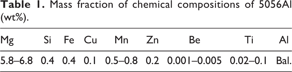
The experimental material is carbon fiber-reinforced aluminum alloy matrix composite. The metal matrix is 5056 aluminum alloy with nominal particle size of 6.7 µm, while the mass fractions of the matrix chemical composition are shown in Table 1. The reason why 5056 aluminum alloy is chosen as the matrix of composite material is that the content of Mg element in 5056 aluminum alloy is high, which is easy to form segregation at the interface between fiber and matrix, and plays a role in inhibiting the interface reaction between carbon fiber and aluminum matrix. The reinforced fiber is PAN carbon (graphite) fiber, type M40J, produced by Japan Toray Company. Each bundle of fiber contains 12,000 monofilaments. The fibers are arranged in one direction, whose basic physical properties are shown in Table 2.
Mass fraction of chemical compositions of 5056Al (wt%).
Basic physical properties of M40J fiber.

Carbon fiber-reinforced 5056 aluminum alloy matrix (Cf/5056Al) composites with volume content of fiber 40% were prepared by pressure infiltration techniques. Firstly, the carbon fiber precast block is made, and the precast block is put into mold, then the mold and precast block are preheated to the set temperature (500–600°C). After that the liquid aluminum alloy at appropriate temperature is poured into the mold, and the pressure is applied at the same time, the aluminum liquid is infiltrated into the precast block, and solidified under the pressure, thus the Cf/5056Al composite is prepared. The annealing heat treatment is carried out of the composite in a vacuum furnace with a temperature control accuracy of ±5°C and a vacuum degree of 10−3 Pa. According to the annealing heat treatment standard of 5056 aluminum alloy, the annealing process of the composite is 330°C/0.5 h + furnace cooling.
In this article, Cf/5056Al composite specimens in tensile and fatigue tests on longitudinal and transverse directions of the fiber are designed with the same size. As the thickness of the composite plate prepared is only about 1.5 mm, it is difficult to clamp it on the mechanical testing machine. The composite material is cut into sheet tensile samples by wire cutting method, and the sample size is shown in Figure 1. Sandpaper is used to remove the traces of wire cuttings, and the side and arc areas are refined to avoid the damage of the composite material caused by the original defects in advance. In order to increase the contact area between the specimen and the fixture, make the load distribution uniform, reduce the stress concentration, and prevent the specimen from being damaged in the clamping section, strengthen the aluminum sheet pasted on the clamping section. The working part in the middle of the sample is polished with metallographic sandpaper until the fiber pattern is exposed, and then it is mechanically polished.

Dimension of the specimen for Cf/5056Al composite (mm). Cf/5056Al: carbon fiber-reinforced 5056 aluminum alloy matrix.
Experimental design
The longitudinal and transverse specimens of the fiber were tensile tested at room temperature, and the longitudinal tensile test of the fiber was carried out before and after heat treatment. The loading rate of the testing machine is 0.5 mm/min. According to the real-time load–displacement curve recorded online, the experimental data are processed to obtain the tensile stress–strain curve, tensile strength, and elastic modulus of the material. In order to ensure the reliability of the test results, the number of samples in each group is 2, and the average value of the test results is taken as the performance index.
The fatigue test of Cf/5056Al composite on fiber longitudinal direction was carried out. The loading frequency was 3 Hz, whose waveform was sinusoidal alternating. The load amplitude decreased from 80% tensile strength step by step, and the stress ratio was −0.4 and 0.1, respectively. The tensile and fatigue tests of FMMCs were carried out on Mechanical Testing and Simulation Systems Corporation MTS-809 electro-hydraulic servo testing machine, with a maximum load of 250 kN and a data acquisition rate of 8 points/s. Strain was measured by extensometer with gauge distance of 10 mm, and the extensometer model is Mechanical Testing and Simulation Systems Corporation MTS-647.25a-22. Scanning electron microscope (SEM) Hitachi Limited HITACHI-S-3400N was used to observe the fracture morphology.
Results and discussion
Tensile properties
The stress–strain curve of FMMC in longitudinal and transverse tensile test is shown in Figure 2. It can be seen from the longitudinal tensile stress–strain curve that the composite is almost linear elastic until the specimen breaks. The longitudinal tensile strength of continuous FMMC is controlled by the strength of fiber, matrix, and interface. Generally speaking, the fiber strength is far greater than the strength of the matrix, which bears most of the load, and the main role of the matrix is to transfer the load between the fibers and protect the fibers.

Tensile stress–strain curves for Cf/5056Al composite. Cf/5056Al: carbon fiber-reinforced 5056 aluminum alloy matrix.
Table 3 shows the comparison of transverse and longitudinal tensile properties of Cf/5056Al composite with that of fiber and matrix alloy. First of all, it can be seen that the longitudinal elastic properties of composite are much lower than that of fiber, and the tensile strength is about one-eighth of fiber, but much higher than that of matrix alloy. Both the elastic modulus and tensile strength are about three times of matrix, which shows that the tensile strength of fiber to composite material. The strengthening effect is obvious. From the comparison of tensile strength and elongation of as cast and annealed composite, the tensile strength of annealed composite is slightly reduced, but the elongation does not change. This is because the annealing heat treatment can eliminate some residual tensile stress in the composite but has no effect on the elongation. Comparing the longitudinal and transverse tensile properties of the annealed state, it can be seen that the longitudinal elastic modulus of Cf/5056Al composite is about six times of the transverse elastic modulus, the tensile strength is about nine times of the transverse, but the elongation is less than two times of the transverse. From the above data comparison, it can be seen that although the transverse properties of the composite are relatively low, it is not lower than one order of magnitude compared with its longitudinal properties, indicating that the interface bonding strength is not very weak, and the longitudinal properties are not higher than one order of magnitude of the matrix alloy or lower than one order of magnitude of the fiber, indicating that the interface bonding strength is not very strong, therefore, according to the macro tensile strength of the composite, it can be qualitatively determined that the interface of this material is of medium strength.
Comparison of tensile properties of materials.

Cf/5056Al: carbon fiber-reinforced 5056 aluminum alloy matrix.
Fatigue properties
The longitudinal fatigue tests of Cf/5056Al composite were carried out with stress ratio at −0.4 and 0.1, respectively. The experimental results are analyzed and discussed through the observation of fatigue life and fatigue fracture morphology.
Figure 3 shows the load life curve of Cf/5056Al composite under stress control, which is characterized by stress amplitude in the longitudinal fatigue test under the stress ratio of −0.4 and 0.1. It was seen that the fatigue life characteristics of Cf/5056Al composite show typical S-N curves due to the linear relationship in the double logarithmic coordinate. The relationship between fatigue load and fatigue life is as follows

where

Fatigue S-N curves of Cf/5056Al composite. Cf/5056Al: carbon fiber-reinforced 5056 aluminum alloy matrix.
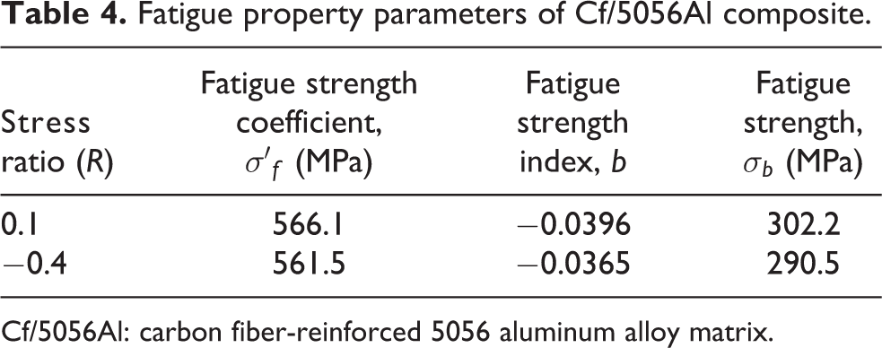
The fatigue performance parameters of Cf/5056Al composite in two stress ratios are shown in Table 4. It can be seen from Figure 3 and Table 4 that under the same stress amplitude, the fatigue life of the composite material when the stress ratio is −0.4 is lower than that when the stress ratio is 0.1. That is to say, the macro impressive stress along the fiber direction is harmful to the fatigue performance of FMMCs. If the stress amplitude under 107 cycles without failure is defined as fatigue strength, when the stress ratio is 0.1, the fatigue strength is 302 MPa, and when the stress ratio is −0.4, the fatigue strength is 290 MPa.
Fatigue property parameters of Cf/5056Al composite.
Cf/5056Al: carbon fiber-reinforced 5056 aluminum alloy matrix.
Fractography
In order to study the fatigue damage mechanism of FMMCs, the fatigue fracture morphology was observed by SEM under different load amplitudes and load ratios. Figure 4 shows the fatigue fracture morphology of Cf/5056Al composite with stress ratio of 0.1, where Figure 4(a), (c), and (e) is the electron micrographs of fatigue fracture morphology from low times to high times under stress amplitude

Fatigue fracture morphology of Cf/5056Al composite (R = 0.1) under stress amplitude (a), (c), and (e)
It can be seen from the low-magnification pictures (a) and (b) that the fatigue fracture presents terrace morphology. When the load is low, there are more steps in the terrace, and the height of each step is larger. It can be seen from Figure 4(c) and (d) that 5056Al matrix alloy is attached to the pulled out fiber on the step fracture of Cf/5056Al composite, which is different from the phenomenon of fiber pulling only due to the lower interface strength. In Figure 4(c), it can also be seen that the matrix alloy with large deformation is left after the fiber is pulled out by the interface debonding. In conclusion, the two phenomena indicate that the bonding strength of the fiber matrix interface is likely to be higher than the shear strength of the matrix, and the longitudinal propagation of the crack is carried out in the matrix, rather than debonding along the interface, and the matrix gives full play to the plastic deformation during the fatigue process.
As can be seen from Figure 4(e) and (f), the fiber section is located in the matrix dimple, and the section height is generally lower than the tearing edge, and the height difference between the two increases with the decrease of load. As the larger the load is, the closer the fracture morphology is to the tensile fracture. However, compared with the tensile fracture, the fatigue striations caused by cyclic load appear on the dimple side wall of the fatigue fracture. No matter high stress amplitude or low stress amplitude fatigue, the step surface in the low-magnification drawing of fracture or the fiber section and matrix tearing edge plane in the high-magnification drawing are perpendicular to the direction of load action, which shows that the fiber plays a role of bridging in the process of material failure. In conclusion, the matrix material plays an important role in anti-fatigue under cyclic loading.
Figure 5 shows the low- to high-magnification SEM photos of fatigue fracture morphology of Cf/5056Al composite at stress ratio R = −0.4. Different from the tension–tension cycle with stress ratio of 0.1, the fracture of one side of the material cracks, and then propagates along the direction of the vertical load for a certain distance, and then the instability split occurs. Therefore, in the left part of Figure 5(a), it can be seen that the stubble is the place where the cleavage occurs. It is worth mentioning that the direction of instability splitting is not completely along the direction of the fiber, but with the fiber at an angle of about 10° to the other side of the sample. Figure 5(b) shows the morphology of the cleavage surface. It can be seen that a large amount of matrix alloy remains on the fiber during the cleavage process. The fiber surface is partially exposed to the tearing surface. This shows that the crack propagates alternately in the matrix and interface. The ductility failure and interface debonding of the matrix under the action of shear stress control the fatigue damage of the composite under the cyclic load of tension and compression.

Fatigue fracture morphologies in different magnification of Cf/5056Al composite (R = −0.4). Cf/5056Al: carbon fiber-reinforced 5056 aluminum alloy matrix.
Figure 5(c) and (d) shows that under the action of tension and compression load, due to the local instability of the fiber, it is easier to promote the debonding of the fiber matrix interface and the cyclic plastic damage of the matrix.
Conclusion
The properties of FMMCs Cf/5056Al composite prepared by pressure infiltration techniques have been investigated under tension and stress control fatigue loadings with stress ratios of 0.1 and −0.4 at room temperature. The main conclusions are as follows: On the fiber longitudinal direction, the elastic modulus of the composite is 212 GPa, the tensile strength is 551.7 MPa, and the elongation percentage is 0.26%. On the fiber transverse direction, the elastic modulus of the composite is 35 GPa, the tensile strength is 59.6 MPa, and the elongation percentage is 0.17%. Compared with the mechanical properties of fiber, composite, matrix, and composite in the longitudinal direction, the elastic properties decrease in this order, but the decrease degree is less than one order. Therefore, the interface of composite is judged to be medium bonding strength qualitatively. Matrix plastic deformation and damage play an important role in the tensile and fatigue failure of composite materials. Under the condition of constant temperature load controlled fatigue, when the stress level is reduced, the influence of matrix failure on fatigue life and fatigue mechanism becomes larger. Although fatigue strength coefficient of the composite behaves little difference under the conditions of stress radio 0.1 and −0.4 (so does fatigue strength index), the fracture morphology shows that the failure mechanism of the two is not the same. Under stress ratio 0.1, the matrix material plays an important role in anti-fatigue under cyclic loading; while under the stress ratio −0.4, the local instability of the fiber promotes the debonding of the fiber matrix interface and the cyclic plastic damage of the matrix. The fatigue damage mechanisms of FMMCs under tension–tension and tension–compression loads are not the same, but the fatigue life curves are close, which may be the result of the medium-strength interface combination.
Footnotes
Acknowledgments
In this article, the preparation of composite materials was completed in the Institute of Metal Matrix Composite Materials and Engineering Technology, Harbin Institute of Technology (HIT), thanks to Prof. Wu Gaohui and Prof. Jiang Longtao. The processing and experiments of composite materials were completed in the State Key Laboratory of Advanced Welding and Connection of HIT, thanks to Mr Zhang Jian and Mr Wang Changli (Material Testing Center). At last, acknowledgment to my PhD Supervisor Prof. Cheng Jin, and bless him healthy and longevity.
Declaration of conflicting interests
The author(s) declared no potential conflicts of interest with respect to the research, authorship, and/or publication of this article.
Funding
The author(s) disclosed receipt of the following financial support for the research, authorship, and/or publication of this article: This article was supported by North China University of Science and Technology (0088/25401699, 0088/25402099).