
Abstract
To determine the thermal deformation of ball screw in actual working condition, a novel method for determining thermal deformation of ball screws in complicated working condition is proposed based on G-code and finite-element (FE) method. In the complicated working condition, it is difficult to obtain and import the nut movement into FE model due to the complex nut movement. In this research, the nut movement is directly determined from G-code by MATLAB code programming. The nut location is recorded with time in a file. The thermal parameters can be determined according to the nut speed with time as well. In the implicit FE analysis, the nut location is read from the input file instead of nut location calculation before every time step. And then, the effect of factors, such as working condition and materials, on thermal deformation reduction of ball screw is studied. The thermal deformation reduction of ball screws under different rotational speed, actual working condition, and different axial elastic modulus of composites is discussed, which can provide the guidelines to evaluate the thermal deformation reduction and design the composite in improved ball screws.
Introduction
The linear speed of ball screw in machine tools is higher and higher due to the application of high-speed machining technology. The high linear speed leads to the thermal deformation issue, which becomes one of the most concerns in the manufacturing domain. It is shown that the thermal error of machine tool caused by temperature rise accounts for about 30–50% of the total error, and this proportion can reach up to 70% in precision machining. 1 Therefore, the thermal deformation reduction is required especially in the high-speed machine tools.
Thermal deformation modeling of ball screws is an important prerequisite for thermal deformation reduction. Finite-element method (FEM) is a popular modeling approach for thermal deformation of ball screw. Wu and Kung, 2 Kim and Cho, 3 and Zaeh et al. 4 established a finite-element (FE) model for ball screws separately. The heat flow is measured by temperature sensors and introduced into the model. The thermal deformation of ball screws is determined. Gao et al. 5 and Oyanguren et al. 6 established a FE model with the thermal parameters calculated from the classical theory to determine the temperature distribution and thermal deformation of ball screw. Li et al. 7 applied FEM integrated with the Monte Carlo method to determine the heat generation rates of two bearings, moving nut, and two guides in the ball screw feed system. Mayr et al. 8 established the equivalent thermal network model of ball screws by an analytical method. Shi et al. 9 and Ahn and Chung 10 mathematically modeled axial thermal expansion of screw shaft. Liu et al. 11 proposed a new robust modeling method to predict the thermal deformation of ball screws based on the heat transfer theory. Min et al. 12,13 predicted the temperature distribution of ball screw by explicit finite difference method considering the thermal contact resistance between nut and screw. Xia et al. 14 proposed a numerical solution to the nonhomogeneous equation of heat transfer in the ball screw by the group explicit finite difference method. The temperature distribution of the ball screw at different times and directions was obtained and validated by experiments. Some research focuses the thermal deformation modeling of ball screws based on the experimental results. Regression analysis is employed to conduct the theoretical modeling of thermal error based on the temperature data of the critical heat generation points in the literature. 9 Shi et al. 15 employed fuzzy clustering and linear regression methods to conduct the theoretical modeling of thermal deformation and optimization to sift out the critical heat sources. The thermal deformation of ball screws was predicted easily according to the experimental result. Above all, FEM is a feasible method to determine the thermal deformation of ball screw with no experiment result, but it is difficult to be conducted in actual working condition due to the complicated nut movement.
In terms of thermal deformation compensation of ball screws, some researchers established the thermal deformation model and then compensated the error in the control system. Zhu 16 established a distributed model of temperature distribution and thermal deformation based on thermal mode analysis. The thermal deformation is real-time compensated based on the model. Kowal 17 proposed a new sensorless compensation method relying on coordinated computation of data fed directly from the drive and the control system in combination with the information pertaining to the operational history of the servo drive, retrieved with the use of an artificial neural networks-based learning system. Xu et al. 18 studied the effect of hollow cooled design on temperature distribution of ball screw. The results indicated that the hollow cooled design decreases the temperature rise and also leads to a rapid temperature balance. To enhance cooling performance and simplify the system, a nut cooling design was developed. The experiment test in the literature 19 demonstrated the effectiveness of the nut cooling design. Advanced material, such as carbon fiber-reinforced plastics (CFRP), is utilized to reduce the thermal deformation according to the negative thermal expansion coefficient of this material. Uhlmann and Marcks 20 and Ge and Ding 21 proposed a thermal deformation compensation method for a spindle based on CFRP. In terms of the characteristic of ball screw, an adaptive method of reducing thermal deformation of ball screws based on CFRP was proposed in our previous research. 5 However, the effectiveness of this method was not fully validated in different working conditions.
In the actual working condition, the nut position with time is usually irregular. The irregular nut position leads to the irregular heat generation, heat transfer coefficient, and the position of heat source as well. It is difficult to determine the temperature and thermal deformation based on conventional FEM. In this research, a novel method of determining thermal deformation of ball screw in complicated working condition is proposed based on G-code and FEM, and then the effect of working condition and materials on thermal deformation reduction of ball screw is discussed.
Methodology and validation
In our previous research, 5 the implicit analysis is conducted to analyze the temperature distribution and thermal deformation of ball screws by FEM. The ANSYS Parametric Design Language command is programmed to simulate the reciprocating cycle of heat flow according to the nut movement. But for a ball screw under actual working situation, the nut movement is not always regular. It is difficult to find the regulation in some working situations. Our previous method is not suitable for actual working situation. In addition, in our previous research, the location of nut should be calculated before every time step so that it wastes much calculation time.
The G-code is usually employed to control the motion in machine tool. Therefore, the movement of every ball screw can be obtained according to G-code. For a ball screw, the nut movement could be directly determined from G-code by MATLAB code programming. The nut location could be recorded with time in a file. In the implicit analysis, the nut location could be read from the input file instead of nut location calculation before every time step, as shown in Figure 1. The heat generation and heat transfer coefficient can be determined according to the nut speed and are introduced into the model.To validate the methodology, an experiment is performed, as shown in Figure 2(a). A thermal imager is used to track the temperature of ball screw. A temperature sensor (KYW-CX1 type) is mounted on the nut to track the temperature of nut and to ensure the temperature balance, as shown in Figure 2(b). The thermal deformation of the ball screw is measured by a dial gauge (Links4086833 type), which is arranged at the end of the ball screw, as shown in Figure 2(c). In the experiment, the ball screw continuously rotates at the speed of 400 r/min. The nut moves in round trips. There is no external load applied on nut. Only the preload is considered in the experimental validation. The temperature and thermal deformation are tracked every 10 min. The experiment is conducted twice to ensure the robustness of the results.The temperature and thermal deformation of ball screw are determined by this method and compared with experimental result, which is shown in Figure 3.
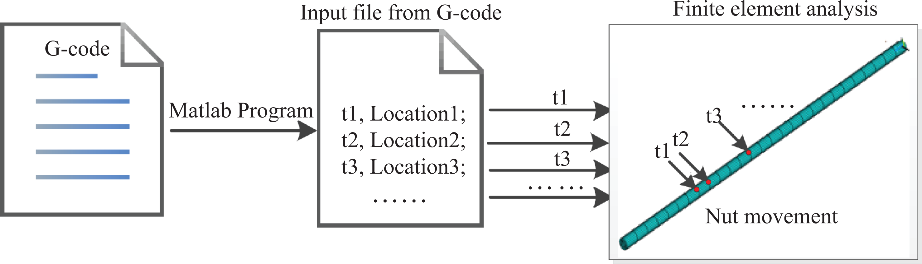
Implicit analysis with the file from G-code.
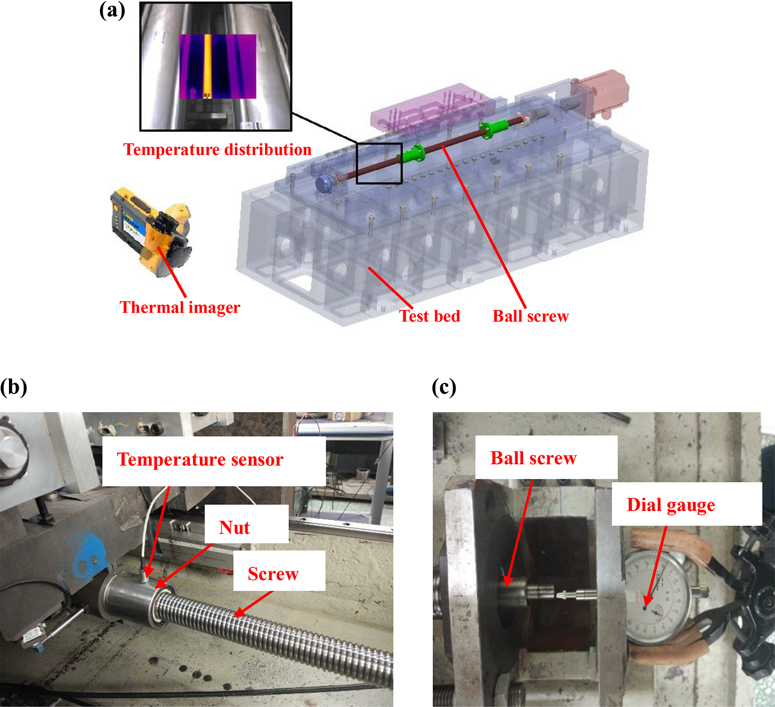
Temperature and thermal deformation measurement for ball screw: (a) Temperature track for ball screw, (b) temperature test for nut, and (c) thermal deformation test.

Comparison between FE results and experimental results: (a) temperature rise and (b) thermal deformation. FE: finite element.
From the comparison in Figure 3, the trend of temperature rise and thermal deformation growth agrees well with each other. The maximum temperature error between the results from the two methods is 16.4%, and the maximum thermal deformation error between them is 14.3% at the temperature balance, which is acceptable in the engineering practice. This method is validated by the experiment. Noting that the calculation time of this method is one-fourth of our previous method. The experimental results are slightly greater than the results from this method. The reason is that the heat generation from bearings leads to greater experimental value. The factor of bearing is not considered in this model as the proportion of heat transferred to the ball screw cannot be determined.
In our previous research, an adaptive method of reducing thermal deformation of ball screw was proposed. The CFRP is mounted inside the screw. When the temperature rises, CFRP will contract the screw due to the negative thermal expansion of CFRP, as shown in Figure 4. In our previous study, 5 the FE model of improved ball screw was established using a solid element. However, the thickness of CFRP is relatively small, leading to the uncoordinated element meshed for CFRP. The size of the element in the thickness direction is far less than that in the other two directions, which causes much calculation time. Therefore, the FE model is improved in this research. The CFRP is meshed with shell element, which is shown in Figure 5. A surface-to-surface bond contact is defined at the interface. The result of this modeling method is obtained and compared with previous study shown in Figure 6. In the simulation, the thickness of composites is 2 mm, and the rotational speed of ball screw is 750 r/min. It is concluded that the steady-state temperature field and temperature rise curve of typical node obtained by the two methods agree well with each other. It is important to emphasize that the calculation time of this improved method is only one-fourth of that of the previous method.

Improved ball screw.

FE model of improved ball screw.

Comparison between two modeling methods: (a) solid element modeling, (b) shell element modeling, and (c) results from two modeling methods. FE: finite element.
Discussion
Based on the method in “Methodology and validation” section, numerical simulation is conducted to discuss the thermal deformation reduction effect of the adaptive method under different working conditions and materials with thermal deformation determined by this proposed method in this article.
Thermal deformation reduction effect of rotational speed
The thermal parameter of ball screw, such as heat generation of nut and the heat transfer coefficient of out surface, is related with the rotational speed ω. Therefore, it is necessary to analyze the effects of rotational speed on thermal deformation reduction of ball screws according to the method based on CFRP under different rotational speed. To investigate the thermal deformation reduction effect, the thermal parameter of ordinary ball screw and improved ball screw should be determined under different rotational speed according to the literature, 22 –27 as presented in Tables 1 and 2. The thermal parameter in Tables 1 and 2 could be introduced into FE model to determine the temperature and thermal deformation of ball screws according to the rotational speed.
Thermal parameters of ordinary ball screw under different rational speeds.

Thermal parameters of optimized improved ball screw under different rotational speeds.

From Tables 1 and 2, it is concluded that the heat generation of nut and heat transfer coefficient increase with rotational speed increase. The heat transfer coefficient of out surface in improved ball screw is the same as that in ordinary ball screw.
The thermal deformation of ball screw is determined according to the method in “Methodology and validation” section. The thermal deformation of ordinary ball screw and improved ball screw is obtained and compared under different rotational speeds, as shown in Figure 7. From Figure 7, the thermal deformation of ordinary ball screw and improved ball screw increases with the increasing rotational speed. The thermal deformation of the improved ball screw is smaller than that of ordinary ball screw under the same rotational speed. The difference between thermal deformation of ordinary ball screw and that of improved ball screw increases with rotational speed increase. Figure 8 shows the thermal deformation reduction effect of the design under different rotational speed. It is concluded that the effect is more obvious with rotational speed increase.

Thermal deformation comparison under different rational speeds.

Thermal deformation reduction effect under different rational speeds.
Thermal deformation reduction in actual working condition
In the actual working condition, the rotational speed of ball screw usually varies with time, leading to the irregular nut movement. In this research, the machining process of a semiconical thin-walled workpiece is studied in this research. The workpiece is manufactured according to the contour method. In the machining process of this workpiece, the ball screw in machine tool has time-varying rotational speed. The nut movement is shown in Figure 9. Therefore, it is a complicated working condition.

Nut position with time.
Figure 9 is obtained from G-code in the numerical control system by MATLAB code programing. To simplify the analysis, the acceleration of nut and the external load on nut are ignored in this research. The thermal parameters, such as heat generation and heat transfer coefficient at inner and outer surfaces of improved ball screw, are determined according to the nut velocity, which are shown in Figure 10 and imported into the FE model. The temperature distribution and thermal deformation of ordinary ball screw and that of improved ball screw are obtained and compared, as shown in Figures 11 and 12.

Thermal parameter with time: (a) heat generation by nut and (b) heat transfer coefficient.

Temperature distribution under complex working condition.

Thermal deformation under complex working conditions.
From Figure 11, the temperature rise of improved ball screw is higher than that of ordinary ball screw. The reason is that the lower thermal conductivity of CFRP leads to the higher temperature rise. Although the higher temperature rises of improved ball screw, it gets smaller thermal deformation than ordinary ball screw, according to the comparison in Figure 12. The reduction effect is 23.16%. Due to the negative thermal expansion of CFRP, the temperature rise of CFRP makes it contract the screw, leading to the thermal deformation reduction of ball screw.
Thermal deformation reduction effect of material properties
The material property of negative thermal expansion is utilized to reduce thermal deformation of ball screw. And the axial elastic modulus of composites is another important factor for the improved ball screw. The axial elastic modulus of composites can be adjusted by choosing reinforcement or volume fraction of the fiber. Therefore, it is necessary to discuss the effect of axial elastic modulus on thermal deformation reduction and further design the proper composites.
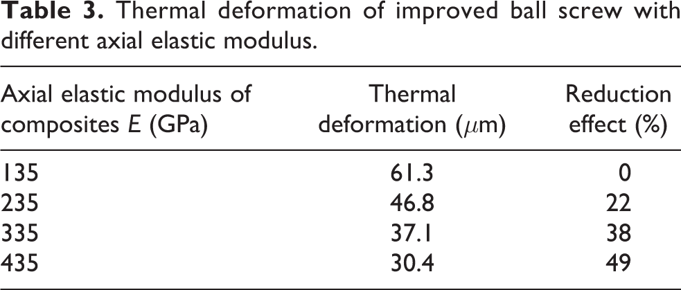
To investigate the effect of axial elastic modulus on the thermal deformation reduction, thermal deformation of improved ball screw with different axial elastic modulus is simulated and compared. Note that the simulations are conducted when the rotational speed is 1000 r/min with initial preload and no external load. The thermal deformation is listed in Table 3. From Table 3, it is concluded that the greater axial elastic modulus will lead to better thermal deformation reduction effect. When the axial elastic modulus of composites is less than the metal substrate, the composite has no effect on thermal deformation reduction, and the thermal deformation of improved ball screw will be greater than that of ordinary ball screw, which is depicted in Figure 13. The conclusion can be drawn that the axial elastic modulus of composites should be designed by selecting the suitable reinforcement or choosing the proper volume fraction of the fiber when the thermal deformation reduction method is applied.

Thermal deformation comparison with different axial elastic modulus.
Thermal deformation of improved ball screw with different axial elastic modulus.
Conclusions
The following conclusions can be drawn from this research: A novel method for determining thermal deformation of ball screw under complicated working condition based on G-code and FEM is proposed. The nut movement can be directly obtained according to G-code in the numerical control system. The heat generation and heat transfer coefficient can be determined by the nut speed with time. The method can be adopted in actual working condition even the nut movement is irregular and complex. In addition, the calculation time of this method is one-third of our previous method. The calculation efficiency is improved in this research. The thermal deformation reduction effect is discussed under different working conditions and materials. Different rotational speeds, actual working condition, and different axial elastic modulus are discussed to validate the effectiveness of this method for reducing thermal deformation and to help choosing the suitable parameter to get a better performance of composites.
Footnotes
Acknowledgements
The authors would like to thank Prof. Chaozong Liu and Dr Maryam Tamaddon from University College London for providing the facility to conduct the simulation.
Author contributions
XG conceived and designed the research, performed the experiment, and wrote the paper as well. YG conducted the simulation and experiment. MW and TZ supervised the research and analyzed the data as well. All authors iteratively discussed and revised the manuscript.
Declaration of conflicting interests
The author(s) declared no potential conflicts of interest with respect to the research, authorship, and/or publication of this article.
Funding
The author(s) declared the following potential conflicts of interest with respect to the research, authorship, and/or publication of this article: This work was supported by the National Natural Science Foundation of China [Grant Numbers 51875008, 51505012, and 51575014] and China Scholarship Council [Grant Number 201806545032].
Supplemental material
Supplemental material for this article is available online.
References
Supplementary Material
Please find the following supplemental material available below.
For Open Access articles published under a Creative Commons License, all supplemental material carries the same license as the article it is associated with.
For non-Open Access articles published, all supplemental material carries a non-exclusive license, and permission requests for re-use of supplemental material or any part of supplemental material shall be sent directly to the copyright owner as specified in the copyright notice associated with the article.