
Abstract
The primary objective of this study is to determine the interphase behaviour of a thermoset epoxy resin that is commercially used for carbon fibre–reinforced composite materials in aerospace structures and a suitable thermoplastic material that can be used as a boundary layer. The thermoplastic boundary layer will be used for welding purposes to join structural components with a fraction of the effort compared to conventional gluing processes. In this study, the interphase formation of an epoxy resin with several thermoplastic materials, namely, polyetheretherketone, polyvinylidenfluoride, polyphenylensulfide and polyetherimide (PEI), is studied via hot-stage microscope experiments. Based on this study, PEI was selected, and a detailed study was performed to determine the dependency of dissolution, diffusion and phase separation mechanisms under various isothermal conditions. Additionally, the welding behaviour was investigated by a resistance welding rig whereby the process parameters were statistically varied to optimize the lap shear strength. The results of this study will enable a statement about the interphase development, the morphology and the mechanical properties which is a key element of fully understanding the process.
Introduction
Carbon fibre–reinforced polymers (CFRPs) are widely used in aerospace structural applications. The requirements on these structural parts are higher in terms of mechanical properties combined with low weight compared to other applications such as automotive and wind energy. This leads to thermoset materials such as epoxy resins that have a glass transition temperature that exceeds 150°C. Therefore, systems are selected that have a high curing temperature of approximately 180°C for several hours. Typically, the structural parts must be connected to other structural parts because differing design concepts are still commonly used instead of integral design concepts. 1 Riveting or gluing is applied to connect various parts in an airplane fuselage. Both methods have advantages and disadvantages. For instance, gluing is not certified for structural applications because the demands on surface preparation, testing of the bond quality and process times are too high. Riveting is typically applied, but the bolted joints weaken the structure due to the creation of holes and the addition of concentrated local stress areas.
The efficient joining of carbon fibre–reinforced thermoset materials for industrial applications is key to enabling lightweight design concepts under the premise of applying the correct material at the correct location. The innovative concept that will be studied in this article is based on a thermoplastic boundary layer with a commercially available thermoset epoxy system that can be used to join parts via welding. Welding has several advantages compared to gluing, for example, due to lower requirements on the surface preparation, the shear strength is higher and the process times are very short. 2–4
This can be achieved by implementing a thermoplastic film on the top surface of a non-cured composite and co-curing the film and the composite (see Figure 1). 5,6 During co-curing, the initially soluble materials are in contact at a temperature typically below the glass transition of the thermoplastic material. The initial solubility implies that mutual diffusion mechanisms occur. During dissolution, the components of the thermoset resin dissolve the thermoplastic polymer chains, followed by diffusion of the materials into one another. While curing, the molecular weight increases and the ability to diffuse decreases and induces a shifting of the decomposition temperature. The critical composition line will cross the curing temperature and triggers a reaction-induced phase separation whereby a gradient interphase is formed. 7–9 The diffusion rate depends on the local concentration, its affinity for the components of the epoxy resin and the thermoplastic polymer as well as their respective molecules. By varying the temperature history, the diffusion depth and morphology of the interphase can be influenced or modified. 8,10

General concept of a thermoplastic boundary layer. CFRP: carbon fibre–reinforced polymer.
The main effect will be a phase separation that is based on the concentration difference between the thermoset and thermoplastic materials. In non-reactive systems, two mechanisms, namely, nucleation/growth and spinodal decomposition, lead to a heterogeneous morphology (see Figure 2). In reactive systems, the process is more complex because effects such as thermodynamics, kinetics of phases and curing influence the phase separation and the resulting morphology is different. In a study by Park et al., 10 the phase separation and morphology development during curing of toughened thermosets were studied using an epoxy system and different compositions of polyetherimide (PEI) particles.
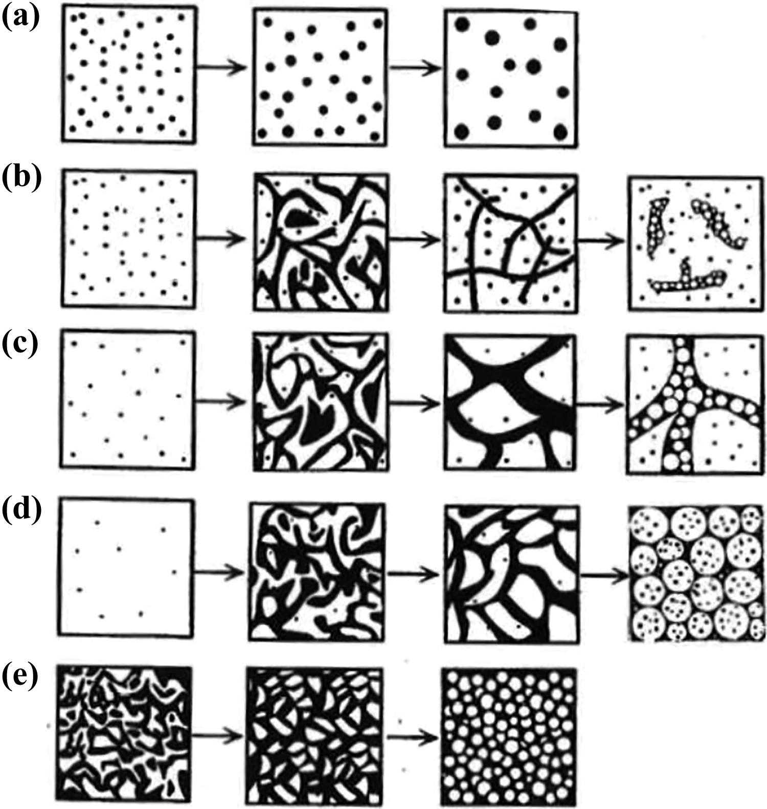
Developed model for morphology formation of Park et al., 10 which depends on the PEI content: (a) NG only (low PEI content), (b) NG followed by spinodal decomposition, (c) bicontinuous NG followed by spinodal decomposition, (d) NG followed by spinodal decomposition with a dispersed thermoset-rich phase and (e) spinodal decomposition only with high PEI content. PEI: polyetherimide; NG: nucleation growth.
In this study, the dissolution of four thermoplastic films in the epoxy resin during the curing process is investigated. The goal was to select the best thermoplastic candidate, which is able to partially dissolve and shows a high diffusion rate and phase separation mechanism with the epoxy system which leads to a pronounced gradient interphase. This candidate was used in a further study to develop a reliable resistance welding with a high average lap shear strength of approximately 36 MPa. 11
Materials
Thermoset material: Epoxy resin 977-2, which was provided by Cytec (Woodland Park, New Jersey, USA), was selected for this study. This system is widely used in aerospace industries due to its high mechanical characteristics and high glass transition temperature (212°C). The resin is used for prepreg application, resin film infusion and resin transfer moulding processes.
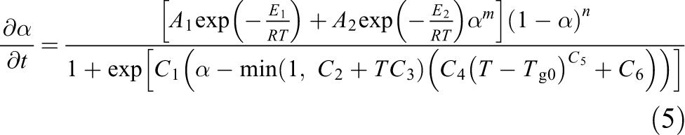
The curing behaviour of the resin was studied via differential scanning calorimetry. Using this method, the exothermic heat flow was measured and interpreted under the assumption that this heat flow is proportional to the degree of cure. Reaction kinetics is typically used to describe a reaction of nth order with α representing the conversion factor (which ranges from 0 to 1), which is also known as the degree of cure. To determine the cure kinetic parameters, a detailed study that consists of dynamic curing tests (heating rates of 20°C min−1, 15°C min−1, 10°C min−1, 7.5°C min−1, 5°C min−1 and 2°C min−1) and isothermal curing tests (160°C, 180°C and 200°C) has been performed on 977-2 resin. The curing behaviour of 977-2 is determined using the standard Kamal–Sourour equation with a diffusion term, 12 which is defined as follows

with

As explained following publications by Garschke et al.
12
and Hein,
13
to account for non-linear temperature effects, a definition of

The function extends the cure kinetic approach for lower diffusion controled curing conditions.

It represents a curing condition above the vitrification point in which the T g is higher than the actual curing temperature. The full form of the equation is
The following parameters are derived, as shown in Table 1.
Cure kinetic parameters for Cytec 977-2 prepreg system.

SD: standard deviation.
This leads to the following results, which describe the curing behaviour of 977-2 prepreg resin (see Figure 3). The model is essentially important to monitor several already mentioned physico-chemical events that take place during the hot-stage microscopy which depend on temperature and time. Additionally, a manufacturing process based on the cure kinetics is derived.
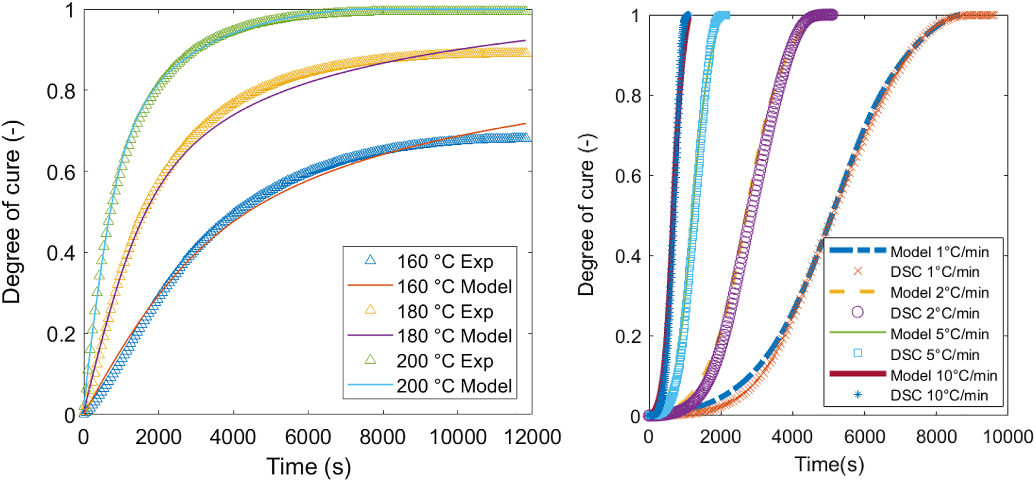
Curing behaviour of 977-2 resin for several isothermal curing conditions (left) and dynamic conditions (right). DSC: differential scanning calorimetry.
Thermoplastic materials: In this study, the dissolution behaviour and the formation of a pronounced gradient interphase of the chosen epoxy resin with various thermoplastic materials, such as polyetheretherketone (PEEK), polyvinylidenfluoride (PVDF), polyphenylensulfide (PPS) and PEI, are studied. The corresponding thermoplastic boundary layer is selected based on several criteria. 4 An important criterion is the possibility of building an interphase. This depends on the dissolution of the epoxy monomers into the thermoplastic materials. In addition, factors that are based on the structural performance of the joined connection are considered. Therefore, the strength/damage resistance, temperature resistance and creep behaviour have a significant impact on the decision. The application of aerospace requirements leads to similar high-performance thermoplastic materials. In structural parts, materials such as PEEK, PPS and PEI are already being used, for instance, as clips/connection elements in the fuselage of the Airbus A350 or in flap systems of the Airbus A380. In Table 2, various relevant thermoplastic materials are listed. Based on this review, PEEK, PPS, PEI and PVDF were selected for further study.
Defined materials for screening.

PEEK: polyetheretherketone; PPS: polyphenylensulfide; PEI: polyetherimide; PVDF: polyvinylidenfluoride.
Preselection of materials via hot-stage experiments
Description of the method: In a hot-stage microscope experiment, a controlled heating device is placed on the microscope table to enable the observation of physical microstructural behaviour as a function of the temperature. Each thermoplastic film was prepared with the size of 10 × 25 mm2 and a thickness of 120 µm. The slit was approximately 3 mm wide (see Figure 4).

Hot-stage microscope and set-up.
First, the thermoplastic film was heated up with a rate of 50 K min−1 to a temperature above the glass transition temperature (depending on the thermoplastic) in order to bond cover glasses and film together. A screw and a toothpick were used to apply a homogenous pressure distribution to ensure an ideal connection between the thermoset and the cover glasses. This is an important point in preventing the flow of the epoxy beneath or above the film. After this, the temperature was decreased to the curing temperature which is typically beneath the glass transition. At this stage, the epoxy was added by dripping it into the slit of the thermoplastic film. As soon as the temperature cooled down to the curing temperature, the epoxy resin was mixed with the amine hardener. After a homogenous mixture was achieved, a toothpick was used to fill the cavity with epoxy resin.
A time-lapse programme was used on the microscope to ensure an image during curing every 15 s in order to characterize the interphase evolution during the curing cycle. Afterwards, a MATLAB script was written and used to proceed the generated images during the curing cycle.
Results of interphase evolution with PEEK/977-2: Various curing cycles were applied to determine the dissolution and diffusion of PEEK with the epoxy. However, PEEK was not penetrated and dissolved by the epoxy resin in the temperature range of 120–190°C (see Figure 5).

Interphase formation at the end of curing: (a) PEEK/997-2, (b) PPS/977-2, (c) PVDF/977-2 and (d) PEI/977-2. PEEK: polyetheretherketone; PPS: polyphenylensulfide; PEI: polyetherimide; PVDF: polyvinylidenfluoride.
Results of interphase evolution with PPS/977-2: PPS was tested with various curing cycles in the temperature range of 120–190°C. Similar to PEEK, it was not possible to identify a dissolution between epoxy and PPS.
Results of interphase evolution with PVDF/977-2: Dissolution of PVDF in Cytec 977-2 epoxy resin was tested initially at 150°C. In this attempt, no dissolution was observed near this temperature. A heat ramp with a rate of 10 K min−1 was applied to the curing cycle and the dissolution was not observed at 160°C. A second heat ramp with a rate of 10 K min−1 was applied up to 170°C. No dissolution was observed.
Results of interphase evolution with PEI/977-2: PEI film yielded satisfactory dissolution and diffusion results which is followed by a reaction-induced phase separation. It remains amorphous during the heating process.
Detailed study of PEI/977-2 dissolution behaviour
In the preselection of materials, the most promising candidate, PEI, was selected for a detailed study. The hot-stage experiments were repeated at several isothermal temperatures, which ranged from 120°C to 190°C. Each experiment was repeated twice. The cure kinetics were used to derive the related degree of cure. During and after curing, the thickness of the gel layer was measured. In Figure 6, the final thickness of the interphase is shown.

Isothermal curing at (a) 120°C, (b) 140°C, (c) 160°C and (d) 180°C. PEI: polyetherimide.
According to the hot-stage results, the diffusion depth depends strongly on the curing temperature. This result is of high importance because it defines the thickness of the pure PEI for the final application. The second important result concerns the duration of the interdiffusion process: If the reaction of the thermoset is too fast, the thickness of the interphase decreases. In Figure 7, the hot-stage experiments are summarized graphically.

Diffusion depth versus isothermal curing temperature.
The dissolution depth is nearly linearly dependent on the temperature. In the region of the final glass transition temperature, the linearity changes, similar to the final degree of curing at the end of the dissolution process. The minimum thickness of the boundary layer is determined to be 80 µm for a conventional curing scenario at 180°C.
Application: Manufacturing and welding
The thermoplastic boundary layer should be used for welding purposes. Therefore, the welding zone must consist of pure thermoplastic material. Welding temperatures for PEI should exceed the glass transition temperature (T g = 217°C). The epoxy material must be separated from the welding zone because the material will be degraded at temperatures that exceed 240°C. To validate the results that were obtained via the hot-stage microscope, at the coupon level, a composite plate is manufactured. A compression tool inside a heat press (Lauffer GmbH, Horb a. N., Germany) was used to manufacture plates with four layers of 977-2 five harness satin (5HS) weave prepreg. The layup was [0/90, 0/90, 90/0, 90/0] with a thermoplastic boundary layer on each side that had a thickness of 125 µm. The plate was cured for 3 h at 180°C. After curing, microsection analysis of the composite was performed. Figure 8 presents a micro-polished intersection with no porosities and the connection of the PEI boundary layer to the composite layup. It can be clearly seen that a linkage between the materials is available because there are no gaps or cracks visible from optical microscopy. To analyse the formation of the gradient interphase, the PEI was removed via etching with N-methyl-2-pyrrolidone and the surface was analysed with a scanning electron microscope (SEM). 13,14

Cross-section optical micrograph of PEI/CFRP manufactured plate sample before welding. PEI: polyetherimide; CFRP: carbon fibre–reinforced polymer.
Figure 9 shows the interphase with an approximate thickness of 80 µm. The result is a pronounced heterogeneous morphology with a thermoplastic-rich phase and a thermoset-rich phase, with strong mechanical interlocking at the micrometer scale. The PEI also propagates into the composite part between the fibres. This etching process was repeated by shortening the etching times to less than 2 s to evaluate the morphology of the transition phase between the two materials.

SEM image of chemical etched cross-section sample analysis out of manufactured composite plate. SEM: scanning electron microscopy; PEI: polyetherimide; CFRP: carbon fibre–reinforced polymer.
In this SEM image, the heterogeneous morphology of the transition phase is visible. According to the change in the concentration from the thermoset to the thermoplastic material, the morphology can be determined. In the studies of Lestriez et al. 8 and Hein, 13 the change in the concentration was found to be linear in the transition zone. Nucleation growth or spinodal decomposition can be observed. The morphology tends to be a spinodal decomposition.
The resistance welding of such specimens was investigated in a custom-built welding rig with systematic variation of relevant processing parameters using a design of experiments, such as shear strength distribution, thermal insulation, compaction pressure, current input, time and moisture content. First, it was important that the process showed a certain stability, such that experiments with nominal equal process parameters (pressure, power, time) could be repeated with a low standard deviation, which is relevant to industrial applications (see Figure 10). An empirically determined parameter setting with power of 65 kW m−2, welding time of 120 s and pressure of 1.2 MPa was used. Ten samples are welded with identical conditions. A mean of 36.3 MPa was achieved with a standard deviation of 1.38 MPa, which corresponds to 3.8%, which was an indication of good reproducibility.
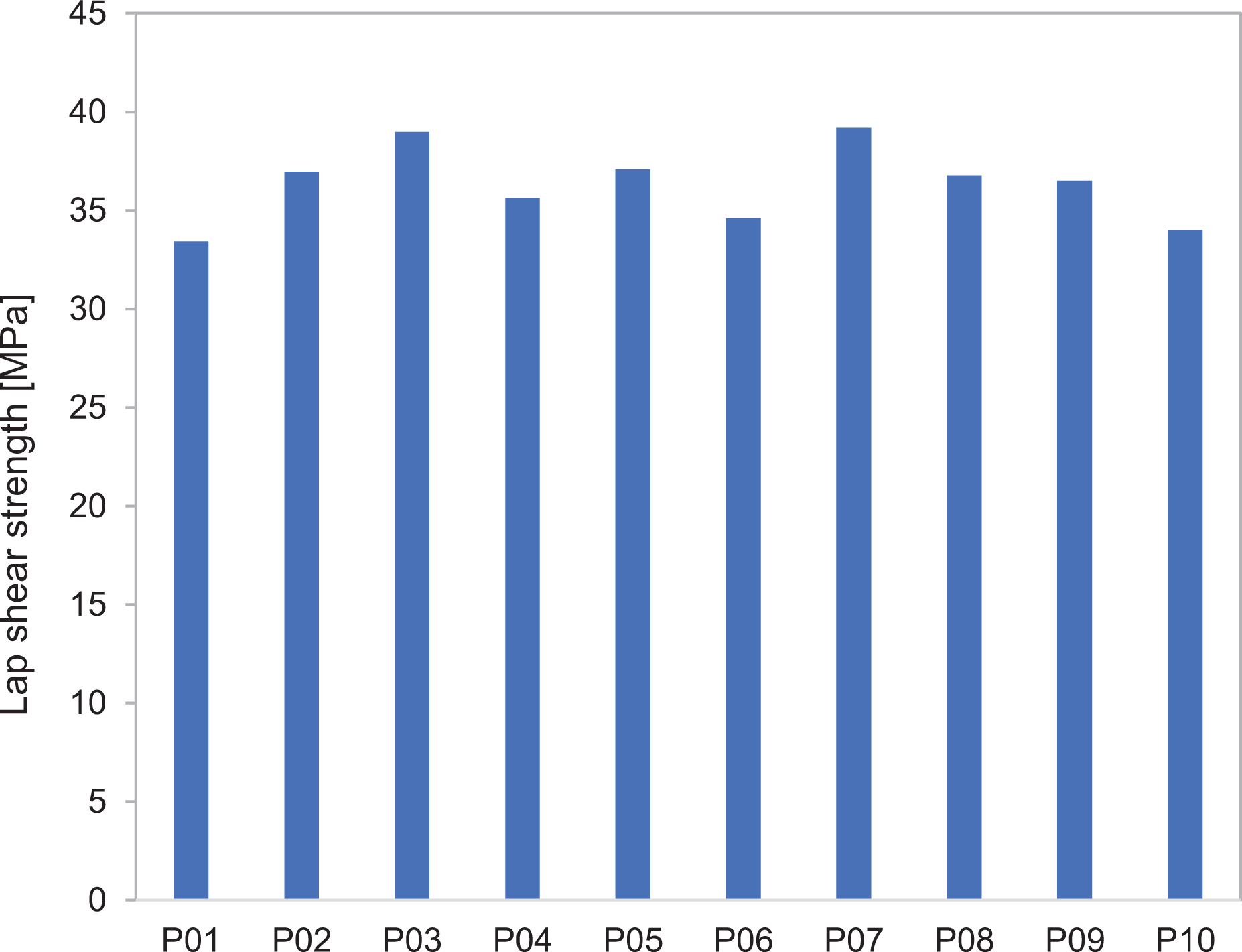
Robustness analysis with lap shear test according to standard ASTM D1002.
The results were used to generate a response surface and thus a processing window with a design of experiments by systematic variation of processing parameters, such as power, time and pressure. This method allowed the computation of confidence intervals of measured data and thus enabled the identification of outliers. The lap shear strength was represented as an implicit function according to y = f(x1, x2, x3), where y is the lap shear strength and x1 to x3 the process parameters. An optimized parameter setting with power of 75 kW m−2, welding time of 120 s and pressure of 1.2 MPa was derived from the model based on the steepest ascent method. This configuration showed a maximum lap shear strength based on ASTM D1002 of 37.5 MPa. The methods have a comparable performance of very good structural adhesive albeit with a much shorter cycle time and high potential for automation.
The analysis of the fracture surfaces in Figure 11 was consistent in the optimum process window. The fracture typology was dominant composite failure within the CFRP or cohesive failure in the metal mesh, but also showed small sections of apparent adhesive failure. This was a strong indication that the interphase between the PEI and the epoxy was stronger than the constituents and showed the potential of a fully developed network between thermoplastic and epoxy.
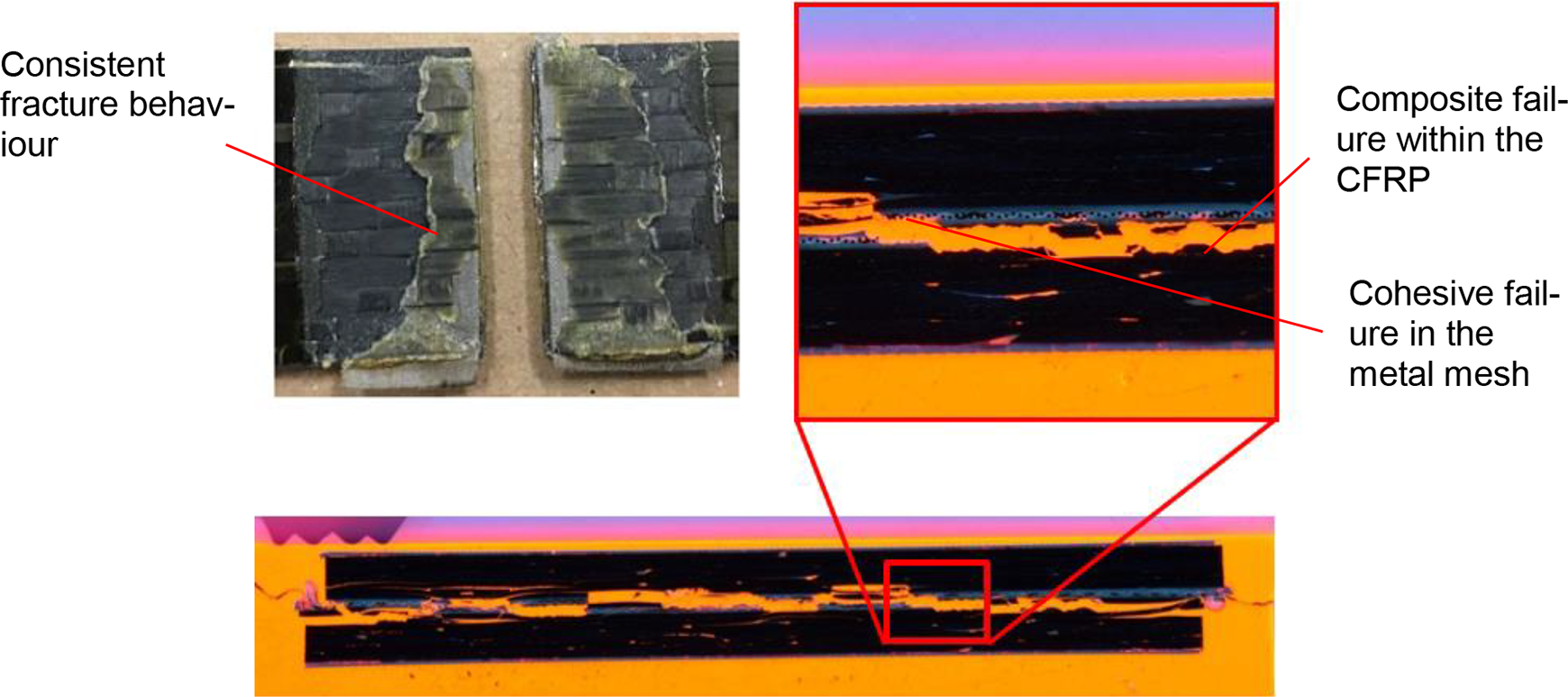
Cross-section micrograph of fracture specimen showing a dominant composite failure. CFRP: carbon fibre–reinforced polymer.
Conclusions
The primary objective of this study was to select an appropriate thermoset and thermoplastic material for manufacturing co-cured composite parts with a thermoplastic boundary layer. This boundary layer should be used to weld the composite parts. In the selection process, a commercially available epoxy system and thermoplastic materials were identified that could partially dissolve, diffuse and build a strong connection via a reaction-induced gradient interphase. As a starting point, PEEK, PPS, PVDF and PEI were analysed via hot-stage experiments. During this screening, the most promising candidate was identified. PEI was selected for a detailed study whereby the diffusion lengths and times at several curing temperatures were determined. A process window was derived with a minimum thickness of the thermoplastic layer of 125 µm and a dissolution time of approximately 12 min.
These results have been applied to a manufacturing application of composite coupons and validate the previous results. The PEI partially dissolves and diffuses well into the composite material. Next, a reliable welding technology was developed for co-cured hybrid composite parts based on resistance welding. The welding was performed with process times that were shorter than 5 min (bonding times of approximately 4 h). An optimum resistance welding process was developed that yields at a relatively high average lap shear strength of 36 MPa with dominant composite failure. 15 Further studies will be conducted to evaluate the performance of these hybrid composite parts and to develop a robust and reliable joining technology.
Footnotes
Acknowledgement
The authors thank Clemens Dransfeld for supporting the hot-stage experiments.
Declaration of conflicting interests
The author(s) declared no potential conflicts of interest with respect to the research, authorship and/or publication of this article.
Funding
The author(s) disclosed receipt of the following financial support for the research, authorship and/or publication of this article: This study was supported by the national funded project Cafimp, no. 25320, which was supported by Innosuisse, Switzerland.