
Abstract
The silicon carbide/carbon fiber (SiC/CF) hybrid fillers were introduced to improve the electrical and thermal conductivities of the epoxy resin composites. Results of Fourier transform infrared spectroscopy revealed that the peaks at 3532 and 2850 cm−1 relate to carboxylic acid O–H stretching and aldehyde C–H stretching appearing deeper with an increased volume fraction of SiC. Scanning electron microscopic image shows a better interface bonding between the fiber and the matrix when the volume fraction of SiC particles are increased. As frequency increases from 102 Hz to 106 Hz, dielectric constants decrease slightly. Dissipation factor (tan δ) values keep low and almost constant from 102 Hz to 104 Hz, has a slight increase after 104 Hz, and obtain relaxation peaks approximately between 105 and 106 Hz. A sharp increase in dielectric constant and dissipation factors is observed in epoxy (Ep)/CF composites with 30 vol.% of SiC. The increase in electrical conductivity of composites may result from the increased chain ordering by annealing effect. The electrical conductivities of the Ep/CF composites are decreasing with the increasing volume fraction of SiC. It is attributed to the introduction of insulating SiC. The glass transition temperature (T g) of the Ep/CF-30 vol.% SiC composite was 352 C, which was higher than other composites. The decomposition temperature at 5% weight loss, decomposition temperature at 10% weight loss, and maximum decomposition temperature of the Ep/CF-30 vol.% SiC composite were about 389.5°C, 410.7°C, and 591°C, respectively, and were higher than pure epoxy and other composites. A higher thermal conductivity of 1.86 W (m K)−1 could be achieved with 30 vol.% SiC/CF hybrid fillers, which is about nine times higher than that of native epoxy resin of 0.202 W (m.K)−1.
Keywords
Introduction
Over the last few decades, thermal control has become a critical factor in the design of electronic parts because microelectronic heat dissipation has become critical to the performance, reliability, and further miniaturization of microelectronics since high integration of transistors has resulted in the escalation of power dissipation as well as an increase in heat flux at the devices’ systems. 1,2
Traditional polymers are both electrically and thermally insulating, and poor thermal conductivity of electrically insulating polymers is a major problem and requires additional heat-dissipating mechanisms such as fans, fins, and heat sinks. 3 To obtain materials with thermal and electrical properties that are acceptable for electronic applications, it is necessary to reinforce them with continuous or discontinuous fibers. 4 However, there are many particle-reinforced polymers used in electronic packaging, primarily because of their physical properties, especially increased thermal conductivity compared to base polymers. For these applications, ceramic particles, such as aluminum oxide, aluminum nitride, silicon oxide, and silicon carbide, are added to obtain an electrically insulating material with higher thermal conductivity and lower coefficient of thermal expansion than the monolithic base polymer. 5,6
Hybrid epoxy composites are used for several industrial applications such as electrical systems; the concept of optoelectronic and electronic devices protects electrical components from short circuiting, dust, and moisture. In the electronics industry, epoxy resin is the primary resin used in overmolding integrated circuits, transistors, and hybrid circuits and is used in making printed circuit board. 7 T. Zhou et al. used carbon-based nanofiller, silicon carbide microparticles and graphite nanoplatelets (GNPs) to improve the thermal conductivity of an epoxy. A result shows that the thermal conductivity reached maxima that were respectively 6.3 and 20.7 times that of the pure epoxy, when adding 12 wt% GNPs or 71.7 wt% silicon carbide microparticles (micro-SiCs) to epoxy. 8
Srinivas et al. reported modification of epoxy by incorporation of particulates of graphene (Gr), SiC, and hybrid (Gr-SiC) at various weight fractions to improve thermal conductivity. The improvement in thermal conductivity for the epoxy hybrid composite containing 20% SiC, 20% Gr and 60% epoxy is 136% when compared with neat epoxy. Significant improvement in the thermal conductivity is observed in 40% filled epoxies. 9
This research work aims to develop a hybrid polymer composite material using ceramic particle (SiC) and using CF, which will retain the advantages of both the fiber-reinforced and particle-reinforced composites and emerges as a viable alternative to the existing epoxy composites. The preparation of composites is carried out using hand layup method. Finally, the prepared composites were characterized for thermal and electrical properties.
Experimental part
Epoxy (OP105; Ep) supplied by DCP (Amman, Jordan) was used as the polymer matrix. The epoxy resin consisted of two parts: part A (diglycidyl ether of bisphenol A) and part B (cyclo aliphatic amine hardener) with a stoichiometric ratio of A:B = 1:3.
A bidirectional Toray’s Torayca T700S-12 k Pan-based CF was used as the reinforcement material in composites, which are commercially available from Zoltek Corporation (St Louis, Missouri, USA). The filler SiC particles are spherical in shape with particle sizes beyond 0.1 µm were purchased from Sky Spring Nano Ltd (Westhollow Drive, Houston, USA).
For preparing composite samples, a weighted quantity of SiC powder with a volume fraction of 10%, 20%, and 30% was first mixed with a measured volume of epoxy resin. Then a hardener was added, and the resulting mixture was well mixed so as to obtain a uniform composition. The hybrid composite is prepared by a simple hand-loop technique. Two layers of woven CFs (0°–90°) were cut according to the dimensions of the mold (150 × 150 mm2). First, Ep-SiC composition was weighed and added into the mold and then the CF mat was put into the mold; the mixture was poured until it covered the entire mat. The mixture was pressed with an appropriate load for the purpose of completing the process of hardening, and finally, the specimen was left in the mold for a period of 24 h at room temperature, followed by heat treatment in an oven at 60°C for a period of 60 min. This process is very important for the purpose of obtaining the best cross-linking between the polymeric chains and for removing the stress generated from the preparation process to complete full hardening of the samples.
The composite specimen was cleaned with acetone to remove moisture, dirt, oil, and other foreign particles.
The infrared (IR) absorption spectra were recorded by a double-beam Fourier transform infrared (FTIR) spectroscopy using FTIR Shimadzu spectrophotometer model 8300 (Japan), with potassium bromide source in the wave number range of 4000–500 cm−1 at a resolution of 0.5 cm−1. Microstructural properties were evaluated using an S-4200 field-emission scanning electron microscope (Hitachi, Japan) at an accelerating voltage of 15 kV, and the sample surfaces were coated with gold to improve the conductivity.
Dielectric parameters were measured using the LCR meter model (HP-4275) at room temperature (27°C) and frequency of 102–106 Hz. The sample to be studied was cut to the same diameter as the copper plates of 40 mm and to a thickness of approximately 3 mm. The apparatus used was the modification of the standard Lees’ disk method for the measurement of thermal conductivity by the absolute plane parallel-plate technique. The samples used for thermal and electrical tests were cut to the same diameter as the copper plates of 40 mm and to a thickness of approximately 500 µm.
Results and discussion
The chemical structures of Ep, Ep/CF composites, and Ep/CF-SiC composites were characterized by FTIR spectroscopy, as shown in Figure 1.

FTIR spectra of Ep, Ep/ CF composites and Ep/CF-SiC composites. FTIR: Fourier transform infrared; Ep: epoxy; CF: carbon fiber; SiC: silicon carbide.
The peaks at 2927 cm−1 and 2862 cm−1 were assigned to C−H stretching vibration of Ep. In case of CF/Ep composites, the broad peak at 3430 cm−1 is due to O–H stretching vibration of hydroxyl groups and the peak at 1712 cm−1 correspond to the carboxylic C=O group attached to CF. 4 These two peaks at 3532 and 2850 cm−1 relate to carboxylic acid O–H stretching and aldehyde C–H stretching appearing deeper with an increased volume fraction of SiC. The presence of this doublet allows aldehydes to be distinguished from other carbonyl-containing compounds. 10
Generally, the image in Figure 2(a) indicates uniform distribution of fiber in the Ep matrix. Figure 2(b) shows a better interface bonding between the fiber and the matrix, which is due to the increase of interaction between the Ep matrix and the CF with increasing the volume fraction of SiC particles. 2,8

Cross-sectional morphologies of (a) Ep/CF composites and (b) Ep/CF-30 vol.% SiC composites. Ep: epoxy; CF: carbon fiber; SiC: silicon carbide.
Figure 3 shows the frequency-dependent dielectric constant. As frequency increases from 102 Hz to 106 Hz, dielectric constants decrease slightly. This behavior can be attributed to the frequency dependence of polarization mechanism. 11 There would be less dipole that can keep up with the oscillations of the alternating electric field; with the increasing frequency, the dielectric constant declined. Figure 4 shows that the dielectric constant increases as the volume fraction of SiC in the polymer matrix is increased, due to which the system becomes more heterogeneous than the pure Ep as more filler is added to it. 12
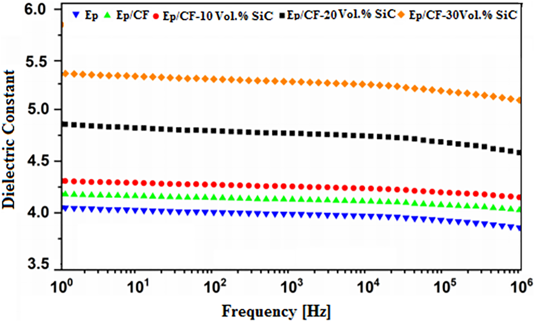
Dielectric constant as a function of frequency for Ep, Ep/CF composites, and Ep/CF-SiC composites. Ep: epoxy; CF: carbon fiber; SiC: silicon carbide.

Dielectric constant as a function of volume fraction of SiC for Ep/CF-SiC composites. Ep: epoxy; CF: carbon fiber; SiC: silicon carbide.
The increase in dielectric constant with an increase in filler is attributed to the formation of clusters. A cluster may be considered as a region in the polymer matrix where particles are in physical contact or very close to each other. The average polarization associated with a cluster is larger than that of an individual particle because of an increase in the dimensions of the metallic inclusion and, hence, greater interracial area. Similar result has been reported in the literature. 11,13
When it comes to dissipation factor (Figures 5 and 6), it can be found that all the dissipation factor (tan δ) values keep low and almost constant from 102 Hz to 104 Hz, has a slight increase after 104 Hz, and can obtain relaxation peaks approximately between 105 Hz and 106 Hz. When the frequency is approaching to 106 Hz, a sharp increase in dissipation factor is observed in Ep/CF composites with 30 vol.% of SiC because the dipoles could just keep pace with the alternating electric field to give increasing friction in the polymer matrix so as to result with elevated tan δ values. 10

Dissipation factor as a function of frequency for Ep, Ep/ CF composites and Ep/CF-SiC composites. Ep: epoxy; CF: carbon fiber; SiC: silicon carbide.
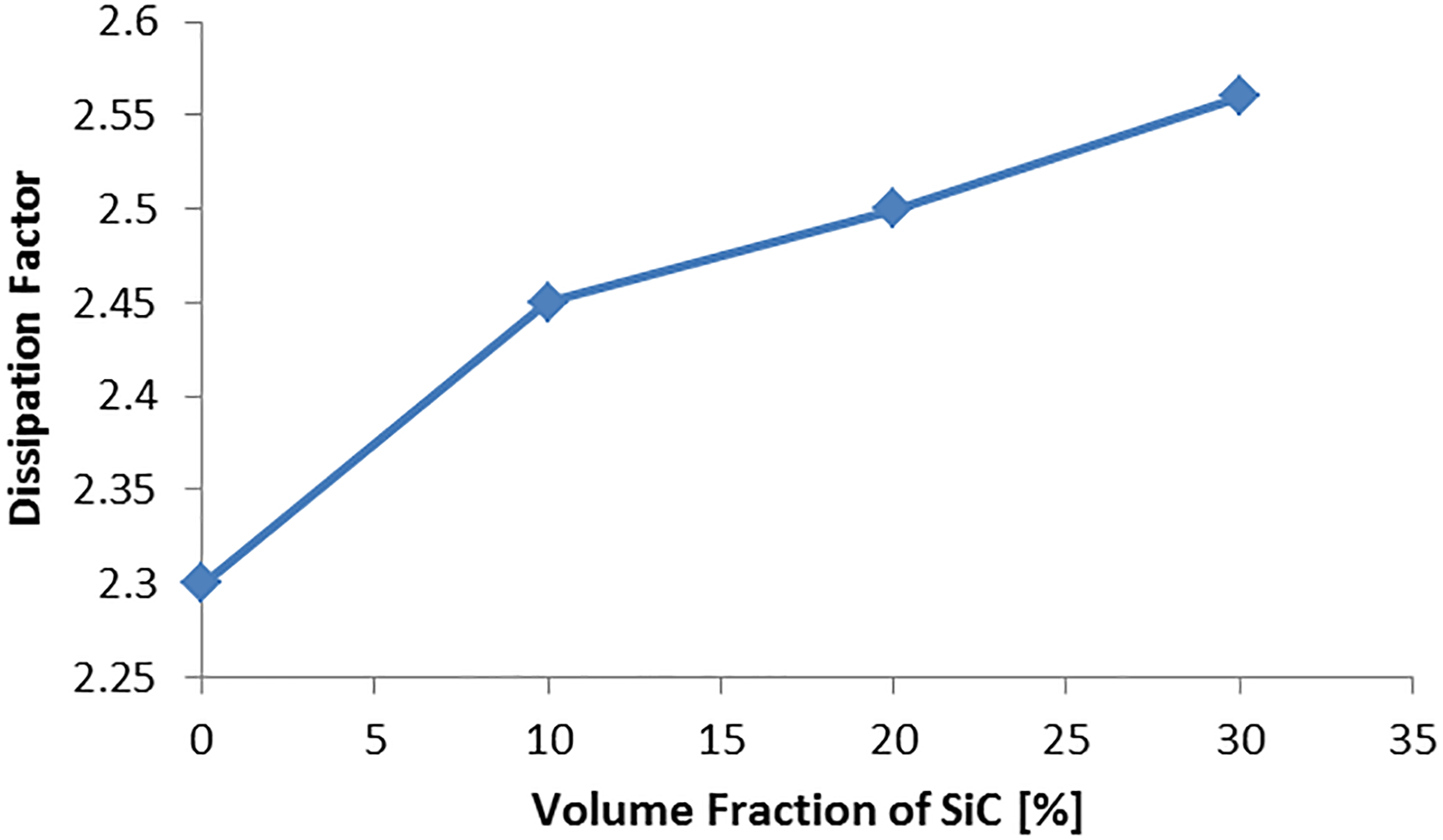
Dissipation factor as a function of volume fraction of SiC for Ep/CF-SiC composites. Ep: epoxy; CF: carbon fiber; SiC: silicon carbide.
Figure 7 shows the dependence of the alternating current (AC) conductivity on temperature, so that we can see σ ac increases when temperature increases. The increase in electrical conductivity of composites may result from the increased chain ordering by annealing effect. When temperature increases, the polymeric chain surrounding the fillers begins to vibrate and straighten out, therefore, increasing the mean free path and phonon propagation length; a similar result has been reported by Kareem et al.. 14 The use of CF and SiC particles pressed a large amount of junctions among Ep composites and increases the electrical conductivity by forming conducting path in the matrix. 15

Variation of ln of σac with 1000/T for Epoxy, CF/Ep composites and Ep/CF-SiC composites.
Figure 8 shows that the electrical conductivities of Ep/CF composites decrease with the increasing volume fraction of SiC. It is attributed to the introduction of insulating SiC, which can effectively prevent the electron getting through CF, to reduce the number of electrons passing through the composites, and finally to decrease the electrical conductivities of the Ep/CF composites. 8,15

Electrical conductivity as a function of volume fraction of SiC for Ep/CF-SiC composites. Ep: epoxy; CF: carbon fiber; SiC: silicon carbide.
Thermal stability of Ep, Ep/CF composites, and Ep/CF-SiC composites with different volume fraction of SiC was examined by thermogravimetric analysis as presented in Table 1; the glass transition temperature (T g) of the Ep/CF-30 vol.% SiC composite was 352°C, which was higher than other composites. This increase in T g might be due to the covalently bonded silane molecules with SiC with CF which introduced a higher degree of cross-links in the composite. Phenolic resin (Ep) is a thermoset material, and it consists of a 3-D network structure in the as-cured condition having an amorphous and glassy structure with a high cross-linking density of CF, and SiC, on the other hand, restricts the movement of molecules, thus resulting in higher T g. 16,17
Thermal analysis data of Ep, CF/Ep composites, and MWCNTs-CF/Ep composites.

T g: glass transition temperature; T 5: decomposition temperature at 5% weight loss; T 10: decomposition temperature at 10% weight loss; T d: maximum decomposition temperature; Ep: epoxy; CF: carbon fiber; MWCNT: multiwalled carbon nanotubes; SiC: silicon carbide.
From Figure 9 and Table 1, the initial decomposition temperature for 5% weight loss (T 5), the decomposition temperature at 10% weight loss (T 10), and maximum decomposition temperature (T d) of the composite were measured.

TGA curves for Ep, Ep/CF composites, and Ep/CF-SiC composites. TGA: thermogravimetric analysis; Ep: epoxy; CF: carbon fiber; SiC: silicon carbide.
It was observed that T 5, T 10, and T d of the Ep/CF-30 vol.% SiC composite were about 389.5°C, 410.7°C, and 591°C, respectively, and were higher than the pure Ep and other composites; this behavior is due to the addition of SiC with CF, in turn improving the decomposition temperature of the composite. 18,19
The strong interaction between the CF and the SiC and the well-bridged and efficient conduction network between the SiC and the CF can retard the diffusion of small molecules from the resin matrix under high temperature and hence result in improved thermal stability of Ep/CF-SiC composite. 8,20
Figure 10 shows the thermal conductivity of Ep/CF-SiC composites increases when the volume fraction of SiC increases. The general theory that explains the conduction mechanism of filler (SiC particle, CF) -filled polymer composites is the “theory of conductive paths,” which suggests that it is the existence of conductive paths (fibers and particle contacts) that results in the conductivity of the composites. With increasing the content of the fillers, conductive paths among the fillers increase, and the average distance between the fillers becomes smaller; thus, the thermal resistivity of the composites decreases and increases the thermal conductivity. 9,18

Thermal conductivity as a function of volume fraction of SiC for Ep/CF-SiC composites. Ep: epoxy; CF: carbon fiber; SiC: silicon carbide.
Conclusions
In this research, we investigated the effectiveness of using hybrid filler (CF and SiC) in a polymer matrix (Ep) to fabricate multiscale composites with reduced anisotropic behavior and heat dissipation and increased thermal conductivity. The results show a better interface bonding between the fiber and the matrix as the volume fraction of the SiC particles increase. A sharp increase in dielectric constant and dissipation factors is observed at 30 vol.% of SiC. The electrical conductivities of the Ep/CF composites are decreasing with the increasing volume fraction of SiC. The T g of the Ep/CF-30 vol.% SiC composite was 352C, which was higher than other composites.
T 5, T 10, and T d of the Ep/CF-30 vol.% SiC composite were about 389.5°C, 410.7°C, and 591 C, respectively, and were higher than the pure Ep and other composites. A higher thermal conductivity of 1.86 W (m K)−1 could be achieved with 30 vol.% SiC/CF hybrid fillers, about nine times higher than that of native epoxy resin 0.202 W (m K)−1.
Footnotes
Declaration of conflicting interests
The author(s) declared no potential conflicts of interest with respect to the research, authorship, and/or publication of this article.
Funding
The author(s) received no financial support for the research, authorship, and/or publication of this article.