
Abstract
The advantages of carbon fiber-reinforced plastic (CFRP) box girders include good bending resistance, lightweight and high strength. Therefore, they are widely used in aerospace, rail transit, and other fields. When the CFRP box girder is subjected to bending load, the strength of the initial damage is usually used as the ultimate load. However, after the initial damage of the CFRP box girder, the load will be redistributed and structure still have a higher ultimate load. As the damage accumulates, it eventually leads to complete failure of the structure, which is a progressive damage. It turns out that the composite structure still has bending capacity after the initial damage, but the mechanical response at this stage has not been fully studied. To make full use of the ultimate bearing capacity of the CFRP box girder, this article adopts the theory of progressive damage of a composite material and programs the ABAQUS/Explicit user material subroutine (VUMAT) to analyze CFRP box girder progressive damage. This article also produces CFRP box girder specimens with five typical ply schemes and implements three-point bending tests to verify the bending strength of the CFRP box girder. In addition, this article designs strain measurement and ultrasonic scanning experiments to verify the difference between experiment and simulation. The final result shows that the progressive damage model established in this article is reliable, among the five typical ply schemes, when the 0° ply ratio is 60% and the ±45° ply ratio is 40%, the CFRP box girder has the greatest ultimate load carrying capacity.
Introduction
A carbon fiber-reinforced plastic (CFRP) box consists of upper and lower flanges and left and right webs, as shown in Figure 1; the section of the CFRP box girder is similar to a box. The box girder section has high bending stiffness, structural stability, and adaptability. 1,2 CFRP box girders also have the advantages of CFRP materials, such as low density, high specific strength, high specific modulus, and anti-fatigue properties. 3

CFRP box girder structure diagram. CFRP: carbon fiber-reinforced plastic.
Based on the above features, CFRP box girders are widely used in aerospace, rail transportation, civil engineering, and other fields. 4 In the aerospace field, the RAH-66 Comanche helicopter was jointly designed by Boeing and Sikorsky, as shown in Figure 2. Numerous maintenance ports must be opened on the fuselage surface to simplify maintenance work, but the traditional semi-hard shell body structure is difficult to design to meet the requirements, so a CFRP box girder was used as the main structure of the fuselage (Figure 3), which also reduces the weight of the helicopter. In rail transportation, the train body of the Regio Shuttle, developed by the German company Adtranz, is constructed with a mixture of a CFRP box girder and metal, as shown in Figure 4. Compared with traditional materials, the CFRP box girder structure reduces the weight of the shuttle by 35%, greatly decreasing energy consumption. 5 In 2011, the Spanish companies ACCIONA and Huntsman Advanced Materials built a CFRP pedestrian bridge 44 m long and 3.5 m wide in Madrid. The internal structure is extensively composite box girders (Figure 5). The bridge is 50% lighter than conventional reinforced concrete bridges, and installation time and cost are significantly reduced.

RAH-66 Comanche helicopter.
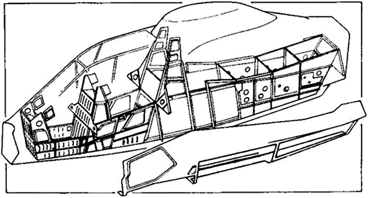
RAH-66 fuselage composite box girder main structure.

Regio Shuttle composite body train body.
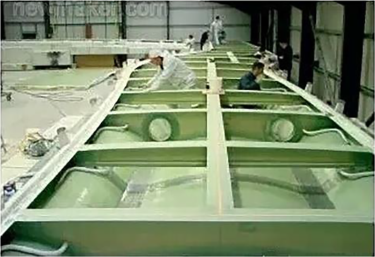
Internal box girder structure of composite bridges.
The bending strength of a CFRP box girder is the maximum stress that can be withstood under a bending load until rupture. Due to the anisotropy of CFRP materials and the complexity of the micromechanics, it is difficult to predict the failure of CFRP box girders exactly. Normally, the allowable bending strength of a CFRP box girder is considered when damage first occurs. This consideration is relative conservative since the allowable bending strength is less than the actual bending strength, which means the bending performance of the CFRP box girder cannot be fully utilized. The reason is that when a CFRP box girder is subjected to bending load, the initial local damage of the CFRP box girder will decrease the structural rigidity, but it does not lead to the overall failure of the structure. Due to the anisotropy of the composite material, the load is redistributed, and the box girder maintains a certain carrying capacity. As damages continuously accumulates, the composite performance gradually degrades, which eventually leads to complete failure of the structure. The gradual failure process is the progressive damage of the CFRP box girder.
To fully utilize the bending capacity of CFRP box girders, the ultimate bending strength needs to be studied and analyzed. Considering the material features and mechanics of CFRP materials, this article proposes to study the ultimate strength of CFRP box girders based on the progressive damage failure mechanism of composite materials.
Previous research on the progressive damage behavior of composite materials has provided a theoretical foundation for this article. In a study of progressive damage, Chang 6 and Tan 7 introduced the method of progressive damage failure analysis to study the failure mechanism of composite structures based on the fragile and brittle nature of the composite. The following research used the progressive damage analysis method to predict the failure and strength of composite structures. 8 Most studies have shown that progressive damage analysis of composite materials can be divided into the following steps: calculating the stress, setting the material failure criterion, building the damage material degradation model, and iterating the above steps until the composite material completely fails. The relevant studies are as follows:
(1) Stress calculation
Chang, 6 Tan, 7 and Sleight 9 analyzed the progressive damage failure of composite materials using the plane stress–strain relationship and calculated stress without considering the interaction between layers. Subsequently, Maimí, 10 Pinho, Silvestre, 11 and Puck 12 used three-dimensional stress–strain relationships to simulate the stress solution and analyzed the failure of bolted connections in composite laminates. Apalak 8 used this method to establish an adhesive lap joint model of composite laminates and calculate stress.
(2) Material failure criterion
After solving for stress or strain in the composite structure, the corresponding failure criteria must be determined. The failure criteria used in the progressive damage analysis of composite materials should not only consider the effect of cumulative damage on the composite material structural strength but also distinguish between different failure-modes. Among them, Hashin 13 proposed a failure criterion based on stress judgment, which is widely used and built into the damage constitutive model by ABAQUS, a prevalent commercial finite element software. Chang focused on the failure characteristics of composite materials and proposed a failure criterion based on strain judgment, which is the most widely used. Since Chang–Chang’s failure criterion only applies to two-dimensional plane stress states, Hou 14 modified the Chang–Chang failure criterion to make it suitable for three-dimensional stress state models.
(3) Material degradation
Currently, most progressive damage failure analysis uses the material sudden degradation model, that is, once composite material damage failure occurs, the stiffness suddenly decreases to zero or a very small value. In the early stage, Chang–Chang, Tan, McCarthy, 15 Camanho, 16 and Tserpes 17 used the sudden degradation model to analyze progressive failure of composite structures. Since the analysis of progressive damage failure using the sudden degradation model is relatively conservative and the accuracy of the analysis cannot be guaranteed, Maimí and Lapczyk 18 used a stiffness degradation model based on fracture toughness, that is, the damage state and patterns are characterized by corresponding damage state variables, so the accuracy of the analysis is improved.
In summary, previous research has performed numerous theoretical and finite element simulation studies, but there are some shortcomings. First, the initial research on the bending strength of composite box girders only focuses on the failure strength of the first layer and greatly limits the high bending strength advantage of composite box girders. Subsequently, some scholars studied the ultimate bending bearing capacity of composite box girders but did not establish a systematic numerical analysis theory or calculation method, which greatly increases the cost of the study. Finally, although some theoretical simulations on the ultimate bending bearing capacity of composite box girders exist, few corresponding experiments exist to verify the theoretical simulations.
Therefore, to establish a precise numerical analysis method for the ultimate bearing capacity of composite box girders, this article studied the bending strength of CFRP box girders based on progressive damage theory. A three-dimensional stress–strain relationship, strain-based three-dimensional Chang–Chang failure criterion, and stiffness degradation model based on fracture toughness were used. Finite element simulation of progressive damage and bending strength of CFRP box girders was performed using ABAQUS. A series of CFRP box girder specimens with several ply schemes were constructed, and three-point bending tests were implemented to verify the bending strength of the CFRP box girders. During the test, the bending stiffness of the CFRP box girder was verified by measuring the strain of the CFRP box girder specimen, an ultrasonic flaw detector was used to scan the delamination damage of the CFRP box girder specimens. Finally, the reliability of the progressive damage model was confirmed.
Simulation of progressive damage of CFRP box girder
Progressive damage analysis of CFRP box girder
The main parts of the progressive damage analysis of CFRP box girders include stress–strain analysis, damage failure judgment, and stiffness degradation model.
① Stress–strain analysis
Due to the complex mechanical behavior of CFRP box girders under bending load, this article proposes the use of a 3-D stress–strain relationship to analyze the progressive damage the CFRP box girder.
② Damage failure judgment
When the box girder is subjected to bending load, the longitudinal fibers are subject to different stresses and the ply angles between adjacent layers differ, which causes the CFRP box girder to be vulnerable to shear failure. Therefore, delamination damage failure is the main failure mode of CFRP box girders subjected to bending load. In addition, other damage modes, such as fiber tensile fracture damage, fiber compression damage, matrix tensile damage, matrix compression damage, and delamination damage caused by interlaminar shear stress or interlayer normal stress, should also be considered.
Because stress distribution in the CFRP box girder changes very sharply before and after damage occurs, compared with stress, the change of strain is gradual before and after composite structure damage, which is more conducive to research and analysis. Therefore, the Chang–Chang strain-based failure criterion was used as the CFRP failure criterion of damage mode for box girders under bending load. The Chang–Chang strain-based failure criterion is as follows:
a. Fiber tension failure (

b. Fiber compression failure (

c. Matrix tensile failure (

d. Matrix compression failure (

e. Stretch delamination failure (
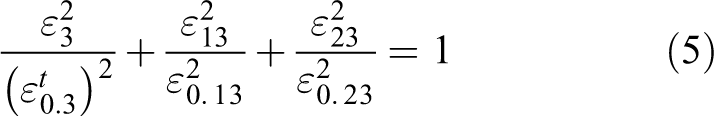
f. Compression layer failure (
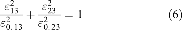
In formulas (1) to (6), each strain is the strain in the main direction of the composite material, 1 is the fiber direction, 2 is the in-plane direction perpendicular to the fiber direction, and 3 is the direction perpendicular to the 1–2 plane.
③ Stiffness degradation model
Since the stiffness degradation model based on fracture toughness can improve the accuracy and computational integrity of the finite element analysis, this degradation model is used to study the stiffness degradation of CFRP box girders. For more accurate results, in the incremental damage analysis, when the final failure strain of a unit is less than the initial failure strain, the sudden degradation model of McCarthy 15 is adopted.
The final failure criterion for progressive damage failure of composite structure adopted in this article is: when the fiber failure of any ply angle in the CFRP box girder extends to the full width of the panel, the CFRP box girder ultimately fails. 16
Based on the above theory, this article proposes the progressive damage analysis procedures for CFRP box girders as shown in Figure 6. First, the stress and strain of each element in the CFRP box girder are calculated under the initial load step, and the failure judgment of each element is made based on the Chang–Chang strain failure criterion. If there is no failure unit, the load step is increased until unit failure and the increasing load step ends. Then, the failed unit adopts a continuous degradation model based on fracture toughness to degrade the material properties. After all the failed units are degenerated, the load step continues. According to the steps above, the unit is judged under a new load step whether it fails or degenerates after failure. This cycle continues until the CFRP box girder fails.

CFRP box girder progressive damage analysis flow chart. CFRP: carbon fiber-reinforced plastic.
Finite element simulation of progressive damage of CFRP box girder bending strength
Development of VUMAT subroutine
The finite element analysis software used in this article is ABAQUS. In the ABAQUS solver module, ABAQUS/Standard can’t guarantee the convergence of the results when handling some contact nonlinear problems, ABAQUS/Explicit are suitable for solving quasi-static and complex nonlinear dynamics problems, 19 so this article selected the ABAQUS/Explicit solver module to handle the mechanics behavior of the CFRP box girder.
Since ABAQUS does not provide the material model required, the user material subroutine (VUMAT) is used to build the material models. A new VUMAT is written to accurately describe the stress–strain relationship of the material in the simulation and reduce the difference between simulation and testing.
Since the VUMAT subroutine cannot directly call the stress and strain of each unit node in the main program, this article defines intermediate variables to store the strain of the node under each load step and uses the three-dimensional stress–strain relationship to calculate the stress of the unit node. Therefore, in the VUMAT subroutine, 18 independent state variables are set in the three-dimensional Chang–Chang failure criterion. The first six independent state variables store the damage state of the units, the middle six state variables store the stress components of the elements, and the final six state variables store the strain component of the elements. After compiling the VUMAT subroutine, a CFRP box girder model must be built in ABAQUS.
Establishing CFRP box girder model
The box girder model requires box girder dimensions, layer scheme, and CFRP material properties.
(1) Box girder dimensions
For the box girder dimensions, the length and cross-sectional size should be determined. Since this article performed three-point bending load tests 20 on CFRP box girders, the length should be determined based on the testing machine range. In this article, a DNS universal testing machine was used, which has a 260 mm support span, so the CFRP box girder length was set to 280 mm. The cross-sectional size of the composite box girder is 40 × 60 mm2. This size was set by the existing box girder mold.
For carbon fiber composite laminates, too many layers may cause delamination damage in the curing process, and considering the limitations of the mold, the CFRP box girder thickness is set equal to 2 mm, the thickness of each layer is 0.2 mm, for a total of 10 layers.
In summary, the CFRP box girder studied in this article has cross-sectional dimensions of 40 × 60 mm2, a wall thickness of 2 mm, a length of 280 mm, and a support span of 260 mm at three-point bending. The specimens and loading device dimensions are shown in Figure 7.

CFRP box girder dimensions and loading schemes (1-load head, 2-CFRP box girder, 3-support). CFRP: carbon fiber-reinforced plastic.
(2) Layer scheme
The upper and lower flanges of the CFRP box girder are mainly subjected to normal stress, and more 0° ply can increase the flange bearing capacity; the left and right webs are mainly subjected to shear stress, and more ±45° ply can increase the web capacity. To fully utilize the performance of the carbon fiber, the final CFRP box girder ply angle should mainly consist of 0° and ±45°. Moreover, 90° ply can improve the overall stability of the CFRP box girder, so 90° ply was added in the design. Therefore, we first designed three-layer schemes with different proportions of 0° and ±45° ply, and considering the function of 90° ply, the other two schemes were proposed. The final five-layer schemes are shown in Table 1.
CFRP box girder layer schemes.
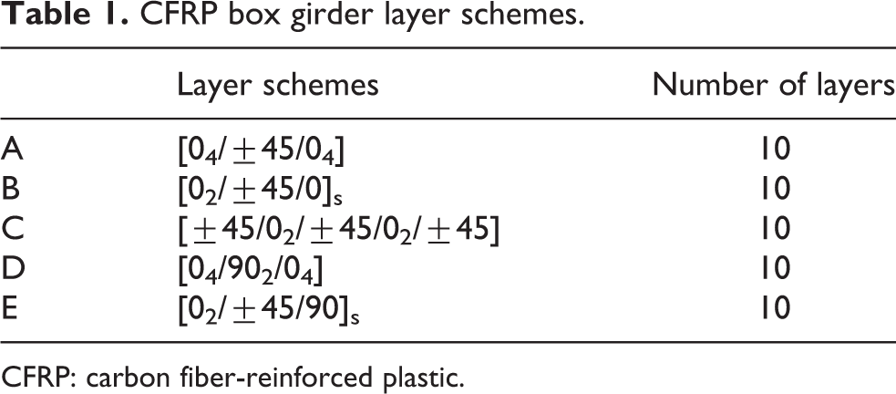
CFRP: carbon fiber-reinforced plastic.
(3) CFRP material properties
The CFRP box girder specimens used in this article were produced using a bag-pressure forming process in Changzhou ShenYing Composite Co., Ltd. The prepreg type is FAW200, and its material parameters are shown in Tables 2 to 4. The 24 material parameters of the FAW200 prepreg were entered into the ABAQUS Property module and assigned to the CFRP box girders.
FAW200 prepreg modulus parameters.

FAW200 prepreg strength parameters.

FAW200 prepreg fracture toughness parameters.

(4) CFRP box girder simulation model
Since the stiffness of the load head and the support seat of the three-point bending experiment is much larger than the CFRP box girder, the load head and the support seat are set as the rigid body during modeling, and the CFRP box girder is set as the deformable body. In the simulation, the contact between the load head and the support base and the CFRP box girder are in face contact, so the load head and the support seat are set as discrete rigid body.
Because the wall thickness and cross-sectional area ratio of the CFRP box girder does not satisfy the thin wall condition, and this article uses the three-dimensional stress to analyze the force of CFRP box girder, so it is meshed by C3D8R solid element. The load head and the support base are discrete rigid bodies, so they are meshed by R3D4 element.
In order to be able to derive the load–displacement curve of the CFRP box girder, as well as to facilitate the application of concentrated displacement loads and constraints on the support, reference points (RP points) are established inside the load head and the two support bases (as shown in Figure 8), and are respectively rigidly constrained with the respective load heads.

Progressive damage finite element model of CFRP box girder. CFRP: carbon fiber-reinforced plastic.
The load head and the support seat are in face contact with the CFRP box girder. Fully constrain the reference points inside the two supports to limit their freedom in any direction. A downward displacement load is applied to the reference point inside the load head. In order to simulate the final bending failure of the CFRP box girder, the displacement load is set to 6 mm and the loading rate is 0.2 mm/min.
FEM results
It can be seen from the “Progressive damage analysis of CFRP box girder” section that if the fiber breakage damage of any one of the laminates extends to the entire width of the upper flange, the CFRP box girder has been completely failed. The final fiber breakage of the five ply schemes is shown in Figure 9. It can be seen that the fiber breakage of the upper flange have been extended to the entire width. Therefore, the CFRP box girders of the five schemes have finally failed.

Upper flange fiber breakage damage.
Using the combine function that comes with the ABAQUS post-processing, the resulting load–time curve and the displacement–time curve are combined to obtain a load–displacement curve, as shown in Figure 11. It can be seen from Figure 11 that the load–displacement curve first increases linearly, and the load decreases after reaching the peak value, indicating that the initial damage has occurred in the CFRP box girder, and the peak value of the load is the conventional ultimate load. However, as the curve fluctuates, the curve rises again to the peak and then falls. This peak is the ultimate load based on the progressive damage theory, at which point the CFRP box girder has completely failed. From the results, the ultimate load based on the progressive damage theory is larger than the traditional ultimate load, which greatly improves the ultimate bearing capacity of the CFRP box girder.

CFRP box girder three-point bending test. CFRP: carbon fiber-reinforced plastic.

Simulation and experimental load–displacement curves of CFRP box girder. CFRP: carbon fiber-reinforced plastic.
The ultimate load of the five schemes is shown in Table 5. It can be seen from the simulation results that the ultimate load of the Scheme B is the largest, which is 7157 N.
CFRP box girder simulation of the ultimate load value.
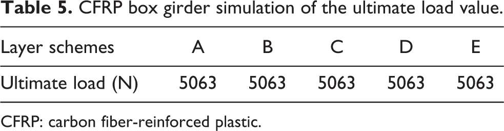
CFRP: carbon fiber-reinforced plastic.
Experimental analysis of CFRP box girder
Preparation of CFRP box girder specimens
The CFRP box girder has a simple structure and strict requirements for the accuracy of external dimensions; therefore, a bag-pressure forming process was selected to produce the CFRP box girder specimens. A total of 18 specimens were produced: Scheme A, Scheme B, Scheme D, and Scheme E have three specimens, and Scheme C has six specimens.
Three-point bending test on CFRP box girder
In the three-point bending test, each CFRP box girder laying scheme has three specimens and are numbered A-1, A-2, A-3, B-1, B-2, B-3, C-1, C-2, C-3, D-1, D-2, D-3, E-1, E-2, E-3. The equipment used is a DNS100 electronic universal testing machine. The span of the bending strength test was adjusted to 260 mm, as cited in the “Establishing CFRP box girder model” section. The CFRP box girder specimens were placed directly on the rigid support seats, and the load head was placed near the box girder upper flange surfaces shown in Figure 10.
The load head of the testing machine was directly loaded on the upper flange of the CFRP box girder, and the loading speed was set to 0.2 mm/min. Since the CFRP box girder may completely fail prior to 10 mm deformation, the maximum displacement was set to 10 mm, and the sampling frequency was set to 10 Hz. During the loading process, the dynamic load–displacement curve and the damage of the box girder were observed in real time. Once the load had obviously decreased or could not be applied upward, meaning the box girder completely failed, loading was stopped manually and the load–displacement data were recorded.
Finally, the experimental data of all specimens were graphed. The load–displacement curves are shown in Figure 11 of the “Test results and analysis” section.
Test results and analysis
The three ultimate loads of CFRP box girders for each ply scheme in the experiment are extracted and averaged. The results obtained are shown in Table 6.
CFRP box girder measured ultimate bending load (N).

CFRP: carbon fiber-reinforced plastic.
From Table 6, among the five-layer schemes, Scheme B has the highest bending strength and Scheme A has the lowest bending strength.
Comparing Scheme A, Scheme B and Scheme C, the proportion of ±45° increases from 20% to 60%, however, the bending strength of the CFRP box girders increases and then decreases. Scheme B has the highest ultimate bending load, consistent with simulation results, which has 0° ply of 60% and ±45° ply of 40%.
Comparing Scheme A and Scheme D, they both have 0° ply of 80%, and the difference is that they have ±45° ply of 20% and 90° ply of 20%. However, the ultimate bending load difference of Scheme A and Scheme D is not large, which means 0° ply dominates the ultimate bending load.
Comparing Scheme D and Scheme E, when the 90° ply ratio accounts for 20%, the 0° ply and the ±45° layup ratio are each 40%, and the bending strength of the box girder is higher. From the overall result, the CFRP box girders with higher number 0° plies have lower strength than those with lower number of 0° plies. Figure 11 shows the load–displacement curves of the simulation and experiments of the five schemes.
It can be seen from Figure 11 that the experimental and simulated load–displacement curves show the same trend, that is, the curve increases linearly first, and the load decreases after reaching the peak, as the curve fluctuates, the curve rises again to the peak and then falls. This shows that the progressive damage theory established in this article can well study the mechanical behavior of CFRP box girder. However, the slopes of the curves for simulation and experiment are somewhat different and this will be discussed in detail in the next section.
Table 7 shows the simulated ultimate load and averaged measured load for the five schemes from Tables 5 and 6. The error between the simulated values and measured values is less than 10%; therefore, the progressive damage theory established in this article is accurate. Among the five typical ply schemes, when the 0° ply ratio is 60% and the ±45° ply ratio is 40% (Scheme B), the CFRP box girder has the greatest ultimate load carrying capacity.
Simulated and measured ultimate load of five schemes of CFRP box girder.

CFRP: carbon fiber-reinforced plastic.
Discussion
As mentioned in the “Test results and analysis” section, there are some differences between the curves for the simulations and experiments, that is, the slope of the simulation curve is greater than the experimental curve, meaning the stiffness is larger in the simulation than the experiment.
Probable reasons for this phenomenon are as follows. ① The carbon fiber composite material is brittle; when the load head of the test machine applied a concentrated load on the CFRP box girder specimens, the load head may easily penetrate the material, and thus, the displacement of the load head is greater than the actual bending deformation of the specimens. ② The present of delamination failure at the interfaces of two plies that having different orientations during the bending tests, which will reduce the strength and bending stiffness of the structure. Therefore, this article implemented the following experiments to verify these reasons.
The reason ① is verified to obtain the bending stiffness of the CFRP box girder by measuring the strain of the CFRP box girder specimens. In this article, three specimens in Scheme D were selected for experiments. Strain gauges were attached to the middle of the outer surface of the lower flange on the specimens. SDY2206 programmable static resistance strain gauges were used to measure the strain values under different loads. The strain gauges on the specimens are shown in Figure 12.

The specimens pasted strain gauges.
During the experiment, the applied load ranged from 0 N to 4000 N, with 400 N increments. The measured strain and simulated strain are listed in Table 8.
Experiment and simulation strain values under different loads of Scheme D.

The measured strain and simulated strain were linearly fitted and the fitted curves are shown in Figure 13.

Scheme D simulation and experimental load–strain curve fitting.
Figure 13 shows that the slopes of the measured and simulated load–strain curves are very similar, indicating that the measured and simulated bending stiffness of the CFRP box girder are very close. This finding explains why the simulated slope of the load–displacement curve is larger than the experimental slope. Carbon fiber composites are brittle, so the load head can easily penetrate the material during the experiment, resulting in the measured deformation being greater than the actual deformation.
For the reason ②, this article uses OLYMPUS EPOCH 1000 phased array ultrasonic flaw scanner to detect delamination failure. This reason is verified to detect whether damage are present in the specimens after the three-point bending experiment.
This article selected three specimens in Scheme D for experiments. The specimen and the probe were immersed in water to eliminate interference from the air. The specimen was divided into seven parts along the axial direction for ultrasonic scanning.
Using specimen D-1 as an example, the ultrasound scan results are as follows:
Before the three-point bending experiment, the results of the seven scanning points on the flange and web are shown in Figure 14.
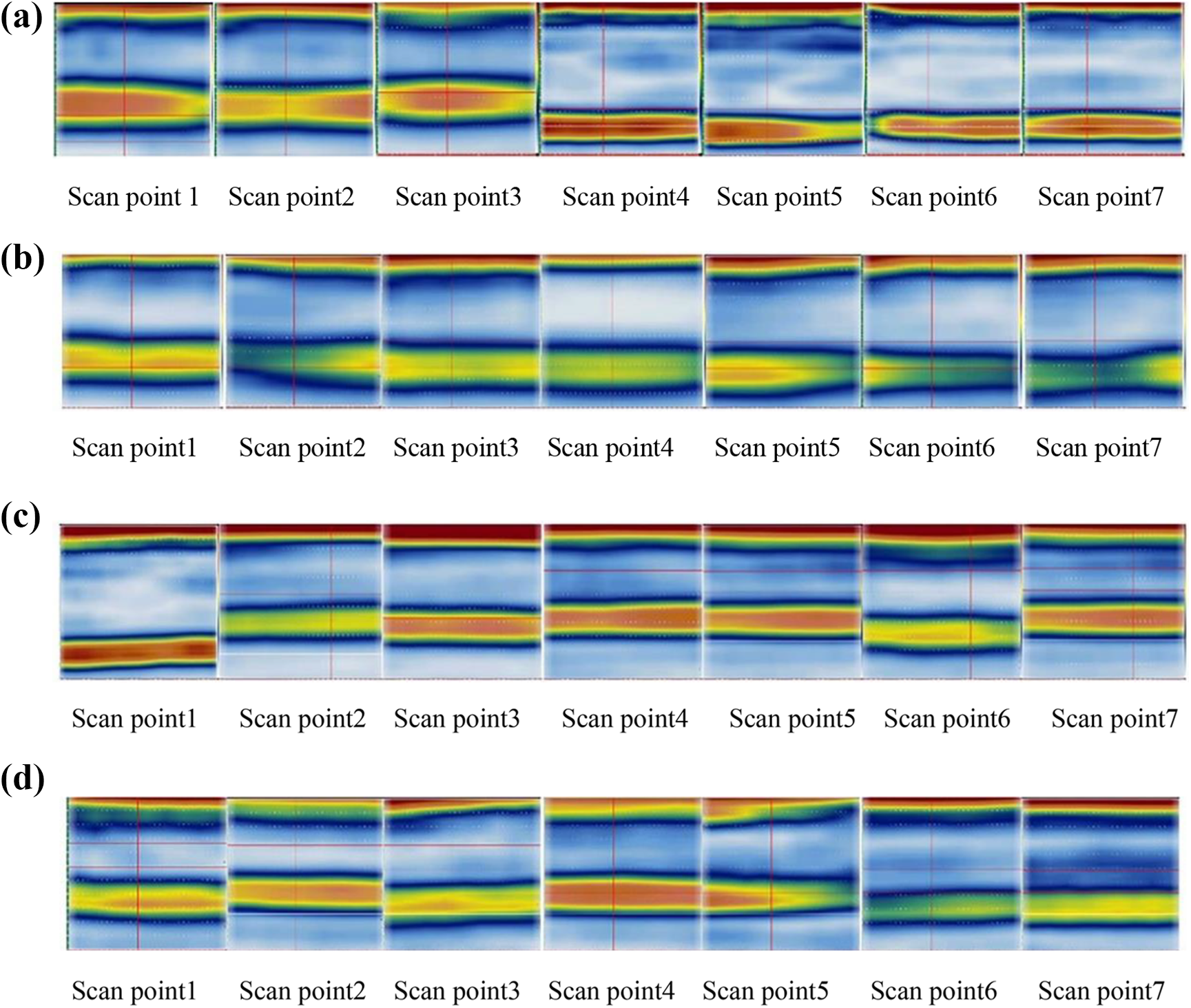
D-1 stratified damage scan results before experiment. (a) Upper flange, (b) lower flange, (c) left web, and (d) right web.
After the three-point bending experiment, the CFRP box girder fails overall, the results of the seven scanning points on the flange and web are shown in Figure 15.

D-1 stratified damage scan results after experiment. (a) Upper flange, (b) lower flange, (c) left web, and (d) right web.
Generally, two color bars are used to represent the initial wave and wake wave. If the laminate is uniform, an air gap is not induced by delamination, and the middle part between the initial wave and wake wave is light. If delamination exists in the laminate, the color of the middle part between the initial wave and wake wave is cluttered. If the delamination damage is serious, the wake wave will disappear or be difficult to identify.
In Figure 14, the initial wave and wake wave of the flange and web before the experiment are relatively clear, and the middle part is a light color. It is determined there is no initial delamination in Specimen D-1. However, when the box girder fails overall, as can be seen from Figure 15, there is obvious delamination failure on the upper flange and lower flange. Therefore, the present of delamination failure results in reduce of the strength and bending stiffness of the structure. The other specimens show the same results, which are not repeated in this article.
In summary, the above two experiments illustrate the difference between the experimental and simulation slopes. Although slopes of the curves for simulation and experiment are somewhat different, the overall trend of the load–displacement curve of the experiment and simulation is consistent, and the ultimate bearing capacity error of the experiment and simulation does not exceed 10%. Therefore, the experiment verifies the progressive damage theory very accurately. The progressive damage theory established in this article can well study the mechanical behavior and the ultimate load of CFRP box girder.
Conclusion
In this article, CFRP box girders with five different ply schemes are used as experimental objects, a systematic numerical analysis theory of the progressive damage of CFRP box girder is established, and progressive damage model is realized by VUMAT, which is programmed to study the ultimate bearing capacity of the CFRP box girder for five typical ply schemes. CFRP box girder experiments were designed, and the result shows:
This article programs VUMAT to realize a theory of the progressive damage of CFRP box girder, and the three-point bending experiment confirms the reliability of the theory. The result shows that experimental and simulation results are consistent. In addition, the ultimate load based on the progressive damage theory is larger than the traditional ultimate load, so the progressive damage theory is reliable, it can be used to study the ultimate bearing capacity of CFRP box girders that may be applied to aerospace, rail transit, and other fields.
The stiffness is larger in the simulation than the experiment, because the carbon fiber composite material is brittle, the load head may easily penetrate the material, another reason is that the present of delamination failure at the interfaces of two plies that having different orientations during the bending tests.
Through simulation and experimental results, we can see that the proportion of ply 0° and ±45° has an effect on the ultimate bearing capacity of CFRP box girders when the total number of layers is the same. In addition, 0° ply has dominated the ultimate bending strength of CFRP box girders, the CFRP box girders with higher number 0° plies have lower bending strength than those with lower number of 0° plies. Among the five typical ply schemes in the article, when the 0° ply ratio is 60% and the ±45° ply ratio is 40%, the CFRP box girder has the greatest ultimate load carrying capacity.
Footnotes
Declaration of conflicting interests
The author(s) declared no potential conflicts of interest with respect to the research, authorship, and/or publication of this article.
Funding
The author(s) disclosed receipt of the following financial support for the research, authorship, and/or publication of this article: This work was supported by the National Science Foundation of China (Project No. 51775400), Hubei Provincial Key Science and Technology Innovation Project (Project No. 2014AAA005), Natural Science Foundation of Hubei Province, China (Project No. 2014CFB829), and the Fundamental Research Funds for the Central Universities (WUT: 2017III044).