
Abstract
Background
Glomus jugulare is a rare, slow-growing tumor that arise within the jugular foramen of the temporal bone. In the past, surgery was the primary modality of treatment for glomus Jugulare, but it leads to many complications and increased mortality. Radiotherapy was indicated in adjuvant setting in post-operative residual disease. But, with the advent of highly conformal radiation planning, stereotactic radiosurgery (SRS), is now one of the main modalities of radiation treatment in glomus jugulare.
Objective
To describe the procedural steps for radiation planning of SRS of glomus jugulare.
Methods
The step-by-step procedure for stereotactic planning of glomus jugulare has been described using a clinical scenario of glomus jugulare.
Results
The stereotactic radiation planning of glomus jugulare starts with the basic history and relevant clinical evaluation, that is, visual testing. Computed tomography (CT) scan and magnetic resonance imaging (MRI) of the brain is the imaging modality of choice. The radiation planning of glomus jugulare starts with CT simulation. MRI of brain should be done in the prescribed format to achieve uniformity in radiation planning. After CT and MRI image fusion, contouring of target, organs at risk (OAR) and radiation planning should be done. The plan evaluation includes target and OAR coverage index, conformity, homogeneity and gradient index, and beam arrangement. After radiation plan evaluation, treatment is delivered after quality assurance and dry run.
Conclusion
The paper highlights the sequential process of radiation planning for SRS in glomus jugulare—starting from simulation, planning, evaluation of plan, and treatment.
Introduction
Glomus jugulare is a rare, slow-growing hypervascular neuroendocrine paraganglioma of the head and neck. It is benign in nature and originates from neural crest derivatives, known as the paraganglia hence termed as Paraganglioma. These tumors secrete catecholamines in response to stimuli and are also called chemodectomas.1, 2 In 1840, Valentin first described the tumor as glomus jugulare. It arises within the jugular foramen and is localized to the jugular fossa in the temporal bone of the skull base. It is the most common tumor of middle ear and the second most common tumor of temporal bone. 1 The annual incidence of glomus jugulare is 1 in 1.3 million. 3 It is mostly seen in the fifth and sixth decade of life and has a female predominance with the male:female ratio of 1:4. 2
Glomus jugulare being indolent in nature are diagnosed late with conductive hearing loss, pulsatile tinnitus as the common symptoms. 1 The tumor is seen as a pulsatile, reddish blue mass medial to the tympanic membrane on otoscopic examination and is referred to as rising sun sign. Computed tomography (CT) scan of the temporal bone better demonstrates the bone destruction in the form of moth eaten appearance and Phelp sign, that is, erosion of bone between carotid canal and jugular fossa. Gadolinium diethylenetriaminepentaacetic acid (DTPA) contrast enhanced magnetic resonance imaging (MRI) better delineates the tumor extent with salt and pepper appearance as a typical sign of glomus jugulare. Hence, a combination of CT with MRI is considered as the imaging modality of choice. 1
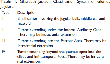
The glomus tumors can be classified as per Lundgren or Glasscock-Jackson or Guild Classification system. Lundgren classified glomus tumors into 2 types—glomus tympanicum and glomus jugulare. Glasscock-Jackson divided the tumor into 4 main types as is depicted in Table 1. Guild classified glomus tumors into 2 types based on histology, that is, cellular glomus and vascular glomus. Earlier, surgery was the treatment of choice for glomus jugulare, but it was associated with increased complications, morbidity, and mortality. 4 In the 1950s, external-beam radiation was introduced as an adjunct to surgical removal of tumors in subtotal resections. Williams et al published the results from the Mayo Clinic in 1955 and noted definite improvement at doses of 13 Gy to 20 Gy delivered to the tumor over 2 weeks. 5 In 1990, Springate and Weichselbaum recommended conventional radiotherapy as the primary modality of treatment of glomus in their review article as it showed similar tumor control to surgery with least adverse effects. 6 In the recent years, stereotactic radiosurgery (SRS) has played a major role in the management of glomus jugulare. This is because of its precision in delivering high dose to the target and rapid dose fall at the periphery of the tumor that helps to spare the critical structures near the target. Further, SRS can be delivered as an outpatient basis and does not require admission to the hospital as is required for surgery. 4
Glasscock–Jackson Classification System of Glomus Jugulare.
Methods
In this article, the various steps of radiation planning for SRT have been illustrated in an easy way with the help of a clinical case as described below. It will be of utmost help for the beginners who are planning for SRS in a case of glomus jugulare.
Results
Clinical Scenario
A 52-year male presented in 2013 with the chief complaints of headache, difficulty in swallowing, and hoarseness of voice for 1 year, reduced hearing, ringing sensation in ear, nasal regurgitation for 6 months. It was not associated with vomiting, giddiness, blurring of vision, double vision, facial weakness, numbness or pain over face. He had no history of any seizures, limb weakness, bowel, and bladder disturbances.
On imaging by MRI of the brain, there was a moderately enhancing mass at left jugular foramen of size 2.7 cm × 2.5 cm × 2.5 cm. The mass was extending into left middle ear, abutting the sixth and seventh cranial nerves. The ninth and tenth cranial nerve could not be separated out. There was widening of jugular foramen with the mass indenting the cerebellar peduncle, extending to carotid canal. The lesion was infiltrating left jugular bulb and proximal internal jugular vein with intracranial extension.
The patient underwent FISCH type approach and excision of glomus jugulare with removal of styloid process and coagulation of tumor adherent to internal jugular vein. The post-operative histopathology showed tumor cells arranged in well-defined nests separated by highly vascularized fibrous septae (zell ballen pattern). On immunohistochemistry, synaptophysin and S100 were positive. Based on these features, the diagnosis was confirmed to be glomus jugulare.
In 2019, the patient again presented with headache, swallowing difficulty, hoarseness of voice, tinnitus, hearing loss, and nasal regurgitation. On examination, there was facial palsy, deviation of uvula, and tongue to right. On vision testing, there was normal bilateral vision. There was left-sided sensorineural hearing loss.
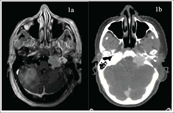
On imaging by MRI of the brain, there was a moderately enhancing hyperintense mass at right para-sagittal and para-falcine region on T2-weighted image (Figure 1a). On fluid-attenuated inversion recovery (FLAIR) image, the mass showed central hypo intensity and peripheral hyper intensity with no restriction on diffusion weighted imaging. There was moth eaten and salt and pepper appearance on MRI and bone destruction on CT scan (Figure 1b).
Magnetic Resonance Imaging (MRI) T2 Sequence of the Brain Showing Hyperintense Lesion in Right Para-sagittal and Para-falcine Region in (1a) and Computed Tomography (CT) Scan Showing Bony Destruction in (1b).
Final Diagnosis
The final diagnosis of glomus jugulare of left jugular bulb post-surgery with recurrence and cranial nerve palsy was reached. It was classified as vascular type as per Guild Classification system and Grade III as per the Glasscock-Jackson Classification system (Table 1).
Treatment Decision by the Tumor Board
The patient details were put in the tumor board for decision regarding the line to treatment. After group discussion with neurosurgeon, interventional radiologist, and radiation oncologist, board decided to plan for SRS.
Discussion with the Patient
Patient was explained about the bouquet of treatment options such as resurgery and radiotherapy, and complications and outcome of each procedure. Further, the radiation treatment procedures, imaging requirement in future, repeat SRS and post radiotherapy raised intracranial tension were also explained to the patient.
Counselling of the Patient
The patient was counselled regarding how SRS works, requirement of embolization in future, obliteration rate, follow-up procedure, and complication rates.
Dose Selection
According to a metanalysis on radiosurgery for Glomus Jugulare, 97% of patients achieved tumor control while 95% of patients achieved clinical control with SRS. 4 As per the above meta-analysis, an average marginal dose varies from 14 Gy to 16 Gy. As the tumor in the present case was close to the brainstem, a marginal dose of 14 Gy in single fraction was selected for treatment.
Decision of Radiation Tumor Board
SRS was planned with a marginal dose of 14 Gy in single fraction.
Radiation Planning
Here we describe the steps of treatment of glomus jugulare from simulation to plan execution.
Step 1—CT Simulation
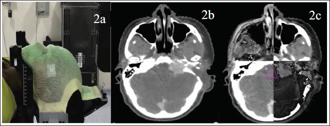
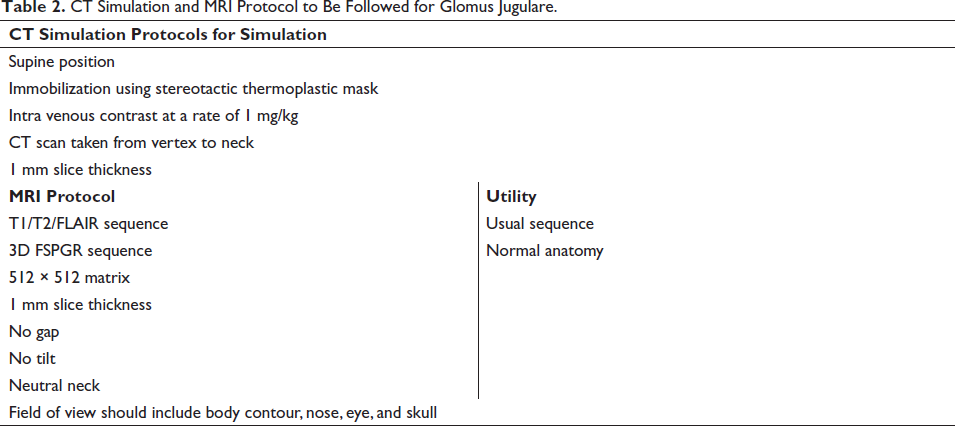
During simulation, patient was set up in the supine position with neutral neck position and immobilization was done using FRAXION thermoplastic mask and stereotactic frame (Figure 2a). Fiducials were placed on the thermoplastic mask after proper alignment with the lasers. Intravenous contrast was given at a dose of 1 ml per kg body weight. Then, CT scan was taken from the vertex to neck with CT slice thickness of 1 mm as is depicted in Table 2 and Figure 2b. After simulation, the Digital Imaging and Communications in Medicine (DICOM) CT images were sent to our Oncentra server which were then imported for delineation of target and organ at risk.
Showing the immobilization of the patient using the stereotactic thermoplastic mask and frame during computed tomography (CT) simulation in lateral view (2a), the planning CT scan taken during simulation (2b), and fusion of the magnetic resonance imaging (MRI) of the patient with planning CT scan after contouring of the brain stem (pink) shown in (2c).
CT Simulation and MRI Protocol to Be Followed for Glomus Jugulare.
Step 2—MRI Protocol
MRI of brain of the patient was done using 512 × 512 matrix in the neutral neck position similar to that of CT scan during simulation with no gap, no tilt, and 1 mm slice thickness as depicted in Table 2. The field of view included the body contour along with nose, eyes, and skull. The MRI should include the usual T1, T2, FLAIR sequences. In addition, the three dimensional fast spoiled gradient echo (3D FSPGR) MRI sequence was used for viewing of the normal anatomy.
Step 3—Image Fusion
This acquired MRI sequences were fused with the planning CT scan by contouring the eyes, lens, basilar artery, and matching was done using auto-fusion technique to help in target and organ at risk (OAR) delineation. Here, the basilar artery was chosen for correcting the axis while matching, while eyes and lens were chosen for correcting any rotational error (Figure 2c).
Step 4—Target Delineation
The gross tumor seen on both the CT images and the MRI images was considered as the exact extension of tumor and was delineated as gross tumor volume (GTV) (Figure 3a). There was no necessity for delineation of clinical target volume in SRS. The planning target volume (PTV) was drawn taking 1 mm around the GTV (Figure 3b). Shaping of the contour was done from the adjacent bone. Multi-planar evaluation of GTV and PTV contours was done in all the three planes, that is, axial plane, coronal plane, and sagittal plane.
Showing the delineation of the gross tumor volume (GTV) (red) of glomus jugulare in the axial plane in (3a), planning target volume (PTV) (pink) generation around the GTV taking 1 mm margin in the axial plane in (3b), delineation of organs at risk, ie, brain stem (pink), left 8th nerve (light pink), right 8th nerve (light blue) in (3c), and brain minus PTV (green) in (3d).
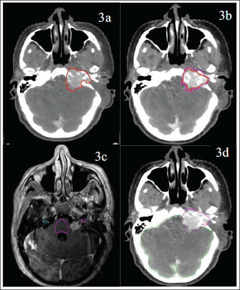
In the present case, the GTV volume was 10.531 cc and the PTV volume was 14.710 cc.
Step 5—Organs at Risk (OAR) Delineation
The OARs for delineation included both the (whole brain minus GTV), brainstem, 8th cranial nerve, optic chiasma, and optic apparatus (Figures 3c,d). They were contoured using the MRI that was fused with the planning CT as per European Particle Therapy Network consensus-based atlas. 7 Also, whole brain minus PTV was considered as an OAR.
Step 6—Radiation Technique
Radiation planning can be done using any of the radiation techniques such as Intensity Modulated Radiotherapy, Volumetric Modulated Arc Therapy (VMAT), Dynamic Conformal Arc Therapy, or 3-Dimensional Conformal Radiotherapy according to convenience of the radiation physicist and the physician.
In the present case, planning was done using VMAT technique.
Step 7—Plan Evaluation
After the completion of planning by the physicist, the evaluation for the treatment plan was done using the following indices.
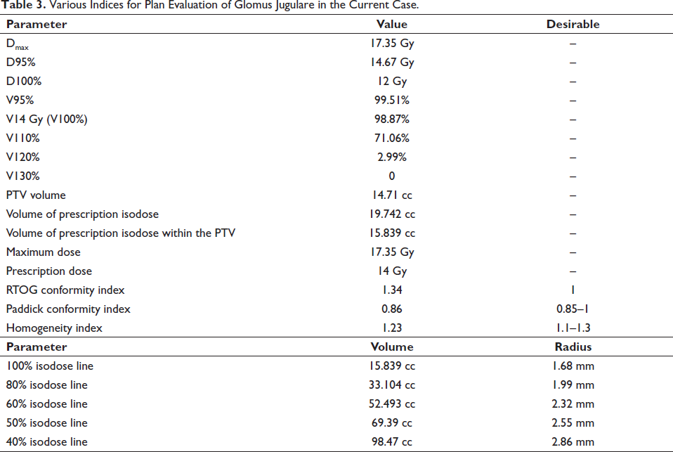
In the present case, 95% of the prescription dose covers 99.51% of the PTV and 100% of the prescription dose covers 98.87% of the PTV which meets the above mentioned parameter for the PTV coverage and is depicted in the Table 3.
Various Indices for Plan Evaluation of Glomus Jugulare in the Current Case.
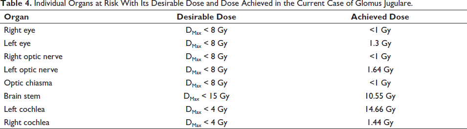
The dose desirable and dose achieved for all the OARs in the present case is depicted in Table 4.
Individual Organs at Risk With Its Desirable Dose and Dose Achieved in the Current Case of Glomus Jugulare.
CIRTOG = Volume of prescription isodose / PTV volume
In this case of glomus jugulare, the RTOG conformity index was 1.34 (Table 3).
CIPaddick = (Volume of prescription isodose in the area of interest, ie, PTV)2 / PTV volume × Volume of prescription isodose
Here in the current case, the Paddick conformity index was 0.86 (Table 3).
Homogeneity index = Maximum dose/Prescription dose
In this case the homogeneity index was 1.23 (Table 3).
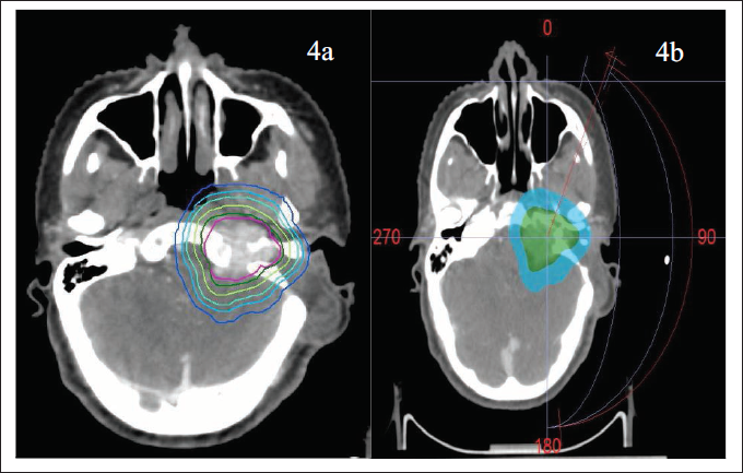
Showing the PTV (pink) and the isodose lines—100% (deep green), 80% (light green), 60% (cyan), 50% (light blue), and 40% (deep blue) in (4a) and beam arrangement in axial view in planning CT scan (4b) for the current case of glomus jugulare.
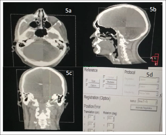
Depicting the treatment verification of the present glomus jugulare case. The Cone beam Computed Tomography (CBCT) correction of the patient during the treatment in axial view (5a), sagittal view (5b), coronal view (5c) and the hexapod correction of the same patient during the treatment (5d).
First: Pick one isodose volume.
Second: Calculate the radius of the isodose volume by using the following formula.
V = 4/3 ύ r3
r = (3V/4 ύ)1/3
The calculation of volume and radius of various isodose lines in the present case is shown in Table 3.
Gradient index = Equivalent radius of 50% isodose – Equivalent radius of prescription isodose.
Ideally the gradient index should be between 0.3 mm and 0.9 mm.
In the current case, the gradient index is 2.55 mm – 1.68 mm = 0.87 mm, which was within the ideal gradient index.
In the current case, it is 2.32 mm – 1.99 mm = 0.33 mm.
The ideal difference between 80% and 40% isodose lines should be <8 mm.
In present case, it is 2.86 mm – 1.99 mm = 0.87 mm.
Step 8—Quality Assurance (QA)
Mechanical isocenter check was done using the Winston Lutz test and the point dose verification was done keeping the tolerance as 1 mm. 14
Step 9—Dry Run
Treatment verification consists of setup reproduction, isocenter verification, and clinically verifying each treatment field—check beam clearance, check any interlock—MLC interlock, and potential Monitor Unit problems. Then clearly mark the immobilzation devices after a successful dry run.
Step 10—Premedication Protocol
Prior to start of treatment, premedication was delivered in the form of tablets as described below—all starting the day before the start of the radiation treatment:
Tablet Dexamethasone 8 mg—1 tablet thrice daily
Tablet Ondansetron 8 mg—1 tablet thrice daily
Tablet Pantoprazole 40 mg—1 tablet once daily
If the patient is diabetic, proper diabetic care needs to be done.
Step 11—Set up Verification and Treatment Delivery
It includes cone beam CT correction (Figures 4a-c) and hexapod corrections (Figure 4d). After all the corrections are done, treatment is delivered.
Step 12—Postmedication
It is an optional protocol that usually includes anti emetics, proton pump inhibitors, and tapering the dose of steroid over a week.
Step 13—Advice and Follow up
After the completion of the treatment, the patient was usually advised for imaging 6 months after completion of treatment.
Conclusion
This paper conceptualizes and acts as an easy guide for the beginners for the stereotactic radiation planning for glomus jugulare.
Footnotes
Declaration of Conflicting Interests
The authors declared no potential conflicts of interest with respect to the research, authorship, and/or publication of this article.
Funding
The authors received no financial support for the research, authorship, and/or publication of this article.
Statement of Informed Consent and Ethical Approval
Necessary ethical clearances and informed consent were received and obtained respectively before initiating the study from all participants.