
Abstract
Various micro-texturing techniques are used to generate the surface topography. However, conventional methods are inherently difficult to adapt for efficient production of micro-textures on cylindrical surface. In this paper, an ultrasonic elliptical vibration-assisted (UEVA) cutting technique based on discussed control parameters is proposed to fabricate the micro-texture on cylindrical surfaces. In the proposed UEVA micro-texturing method, a control model is developed based on shape and distribution parameters for the micro-texture. The locus of UEVA cutting is actively controlled with this EVA model to generate the micro-texture. The simulation model based on the proposed micro-texturing method is developed to predict the topography of the generated micro-texture. The cutting experiment to produce the micro-texture is conducted to verify the established control model. A comparison of the obtained results shows that the proposed UEVA micro-texturing method can be used to predict and generate the micro-texture on the cylindrical surfaces.
Keywords
Introduction
Surfaces with micro-/nano-textures enhancing the functional performance of components have attracted the attention of industry. Many surfaces’ functions are improved by the micro-/nano-structures manufactured specifically for industrial application in aerospace, tribology, and other fields.1–3 In order to obtain such functional surfaces, a high-efficiency manufacturing technology is required for the fabrication of micro-/nano-structures on component’s surfaces. There are many fabrication processes4–9 to obtain micro-textures such as laser machining and micro-machining. In these methods, micro-machining has flexibility advantages, since different work materials can be processed and different complex micro-features can be generated. 10 With ultrasonic elliptical vibration-assisted (UEVA) cutting, mechanical micro-machining is a potential machining process for micro-structured surfaces with the wavelength of tens of micrometers. 10
Suzuki et al.11, 12 proposed a new ultra-precision sculpturing method for micro-/nano-structure by utilizing variations of an elliptical vibration locus. Zhang et al. 13 further explored ultra-precision nano-structure fabrication with an amplitude-controlled sculpturing method in elliptical vibration cutting (EVC) considering compensation. Ping et al.14, 15 focused on the fast generation of dimples on cylindrical surfaces and the micro-channeling topography was obtained with their texturing method. Gandhi et al. 16 investigated the control of underlying process parameters in vibration-/modulation-assisted machining to generate micro-scale textures with prescribed size and morphology and corresponding geometric surface models were developed. Xu et al. 17 proposed a novel rotary ultrasonic texturing technique to fabricate hybrid micro-/nano-textures on flat surfaces by using a tailored one-point diamond tool. A four-axis end-flying-cutting servo system was proposed for the generation of hierarchical micro-/nano-structures. 18 With the combination of fast tool servo and fly-cutting technology, the end-flying-cutting servo system is limited in its efficiency and adaptation of machining materials; for instance, it is not applicable to machine steel due to rapid tool wear and surface deterioration. 13 Kim and Loh 19 investigated the parameters of EVC in micro-V grooving considering the variations of the elliptical cutting locus and the excitation frequency. Lee et al. 20 presented a simulation software for micro-pattern cutting. It models the micro-grooving in 3D, predicting the cutting force and optimizing the time for the roughing stage. Wang et al. 21 proposed a fabrication method for structurally colored basso-relievo by combining the surface sculpturing and elliptical vibration texturing in one-step machining and synergistic modulations of both nominal cutting speed and depth-of-cut (DOC) in elliptical vibration texturing are applied to provide concave–convex topography and structural coloration. For fabricating micro-textured surface efficiently and cost-effectively, a texturing method of radial ultrasonic vibration-assisted turning (RUVT) was proposed and the theoretical model of texturing generation was established, which can describe the arrangement and geometry of micro-textures. 22 Liu et al. 23 proved that the formation of nano-scale structure originates from pile-up produced by ultrasonic dynamic indentation. Both quasi-static and dynamic indentations are performed on pure copper, 316 stainless steel, and pure titanium using an ultrasonic nanocrystal surface modification system.
However, the micro-/nano-texture with different geometric parameters is difficult to fabricate by using the elliptical vibration locus. Such surface structures are required for various applications like reduced rotary shafts. For such applications, it is necessary to understand the cutting mechanism of micro-texture turning with elliptical vibration assistance and predict the generated features. Our previous studies demonstrated that dimples can be generated on cylindrical surfaces with UEVA cutting.24, 25
In this paper, an UEVA cutting technique based on a control model is proposed to fabricate micro-textures. In the proposed UEVA cutting micro-texturing method, the control model for the generation of micro-texture is established based on shape and distribution parameters of this micro-texture. The simulation model of the generated micro-texture is developed to predict its topography.
The structure of the paper is as follows. First, UEVA cutting micro-textures are described in section “Mechanism of UEVA cutting micro-texture.” Subsection “UEVA cutting micro-texturing process” is the UEVA cutting micro-texturing process; subsection “Development of control model” is devoted to the development of the control model for micro-texture parameters; subsection “Simulation method for micro-texture topography” presents the simulation method for the micro-texture topography; and realization of locus control and simulation software is discussed in subsection “Realization of locus control and simulation software.” Section “Fabrication of micro-texture” is about the fabrication of micro-texture on cylindrical surfaces. The experimental setup and procedures for micro-texturing are given in subsection “Experimental analysis;” generation of micro-textures on cylindrical surfaces is described in subsection “Experimental results;” and the experimental results are analyzed, and a comparison between results of the theoretical data and experimental results are provided in section “Discussion.” The last section is “Conclusion”.
Mechanism of UEVA cutting micro-texture
UEVA cutting micro-texturing process
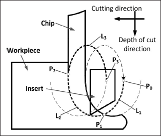
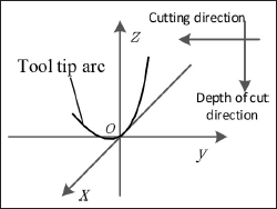
In micro-texturing, an elliptical locus is generated by 2D vibration of the tool tip and the feed action of the workpiece, as shown in Figure 1, with a single vibration cycle following path
Principle of elliptical vibration cutting process.
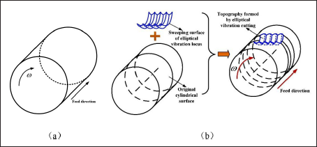
The generation of micro-textures by using UEVA cutting method is shown in Figure 2. The process results in wavy dimples produced on the cylindrical surface along the circumferential direction. Obviously, the topography of the micro-texture in the circumferential direction is the intersection result of the neighboring elliptical loci. In this method, the UEVA cutting locus based on a micro-texturing model is a key. The following section describes the process of development of a control model for a micro-texture process.
Generation of UEVA cutting micro-textures: (a) original surface and (b) micro-textured topography.
Development of control model
As discussed for the elliptical vibration-assisted micro-texturing process, the features of micro-texture are mainly defined by its shape parameters and distribution parameters; these parameters are introduced in Figure 3(a):
Schematic of micro-texture parameters: (a) parameters of micro-texture and (b) cutting locus of micro-texture.
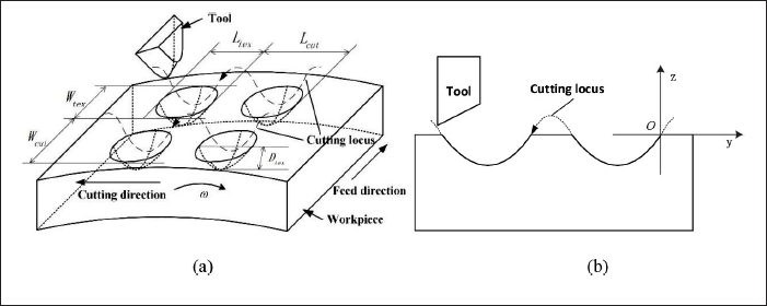
The coordinate system o-xyz is set up with its origin located on the workpiece surface (Figure 3(b)). Axis x aims at the inverse cutting direction, while axis z coincides with the radial direction, and axis y is defined by the right-hand rule. For the given machining parameters: cutting velocity, feed velocity
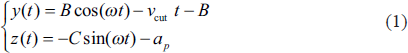
where
Thus, the shape and distribution parameters of the micro-texture in Figure 3(a) can be expressed as in Table 1 based on the equation of the elliptical vibration locus and machining conditions.
Calculation of micro-texture parameters.
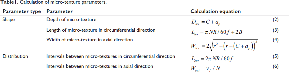
Therefore, in order to generate the micro-texture with different parameters, the machining conditions and vibration parameters should be controlled according to the parameters in Table 1. From Equation (2), the depth of cut ap is defined as:

The level of spindle speed based on Equation (5) can be obtained as:

while the feed velocity is determined from Equations (8) and (6) as:

According to Equation (3), the amplitude in the cutting direction is defined as:

Thus, Equations (7)–(10) represent the control model of micro-texture parameters. The locus of UEVA cutting should be used based on Equation (10) to generate the required micro-texture on the machining surface.
Simulation method for micro-texture topography
In order to predict the topography of the micro-texture generated by UEVA turning, the simulation model is developed to understand the micro-texturing generation process. The simulation model describes the equation of tool tip arc in the established workpiece-related coordinate system. The simulation model for surface of the micro-texture generated on the cylindrical surface is discussed in detail below.
Workpiece’s coordinate system.
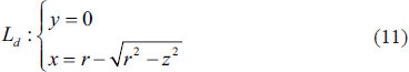
where r is the radius of the tool tip arc.
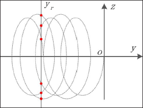
In the same system, the equation for the elliptical locus of the ith line along the axial direction of the cylinder has the following form:
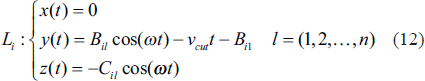
The coordinate yr of the elliptical locus curve
Schematic of sweeping line.

Considering the cutting depth, the micro-texture topography of the ith elliptical locus can be obtained by mapping Sdi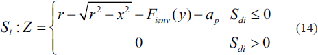
Realization of locus control and simulation software
The locus control and simulation software of elliptical vibration (LocusSimUEVC) was developed by using the information and communication functions. It was used to simulate the surface topography of micro-texture in the UEVA cutting process. Section “Fabrication of micro-texture” compares simulation results on surface topography and the actual machining data for the micro-texture generation process in this cutting process.
Fabrication of micro-texture
Experimental analysis
Experiments with the UEVA micro-texturing turning were performed on a DMG ULTRASONIC 20 linear machine, with the developed ultrasonic-vibration system integrated into it (Figure 6(a)). Its x-y stage carried the motion generator. The Ultrasonic 20 machine was configured to operate as a lathe in the vertical direction to conduct the micro-texturing experiments. The z-axis was aligned with the spindle’s axis with the workpiece loaded along this axis. The spindle provided the primary motion for the turning operation and controlled the feed, while the x-y stage set the depth of cut. Sinusoidal excitation voltage of varying magnitude and phase for an ultrasonic-vibration generator was generated.
Schematic of UEVC machining system: (a) UEVC machining system and (b) machined micro-textures.
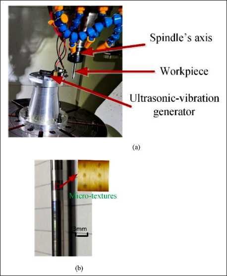
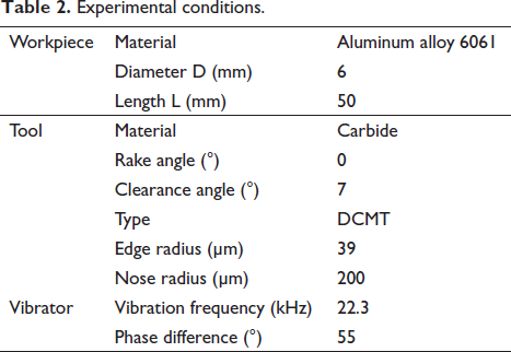
To investigate the elliptical vibration-assisted machining of micro-texture, the micro-texturing experiments with elliptical vibration cutting were performed and the aluminum alloy 6061 is used. The cutting tool used was commercial tungsten-carbide inserts and its nose radius is 200 µm. The resonant frequency and the phase difference of the elliptical vibrator were 22.3 kHz and 55°, respectively. The spindle speed was 1,500 rpm, the depth of cut was 0 mm, and the feed rate was 1,000 µm/min in the machining experiments; Table 2 presents the experimental conditions. Typical results of micro-textures for aluminum-alloy workpiece are shown in Figure 6(b) for parameters of the UEVA cutting process prescribed.
Experimental conditions.
Experimental results
Five groups of micro-textures with different depths were designed for machining experiments on DMG ULTRASONIC 20; the same machining parameters (see subsection “Experimental analysis”) were used in these tests.
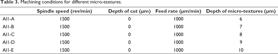
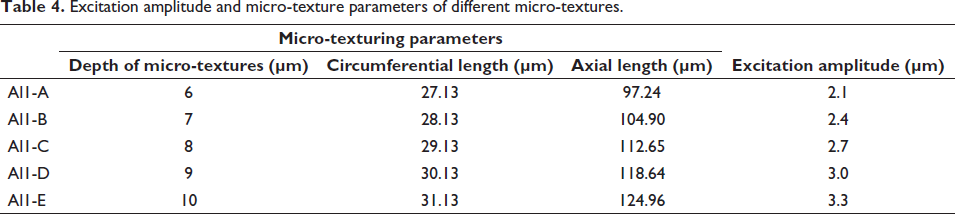
Based on the five designed cases, the corresponding machining parameters can be calculated as shown in Table 3. A change in the vibration amplitude allowed the generation of micro-textures with different prescribed depths of cut in the range from 6 to 10 µm. The respective parameters of these micro-textures were obtained by employing the approach developed in section “Mechanism of UEVA cutting micro texture;” they are listed in Table 4.
Machining conditions for different micro-textures.
Excitation amplitude and micro-texture parameters of different micro-textures.
All five groups of generated surface topographies were measured by using a 3D white-light interferometer UP Dule. The actual machined profiles and simulated topographies are compared in Figures 7–11. Obviously, the simulation process only considered a perfectly sharp tool with ideal geometry of its edge and did not account for tool wear, and so on. Therefore, the machined micro-textures demonstrated some differences when compared with the simulation results.
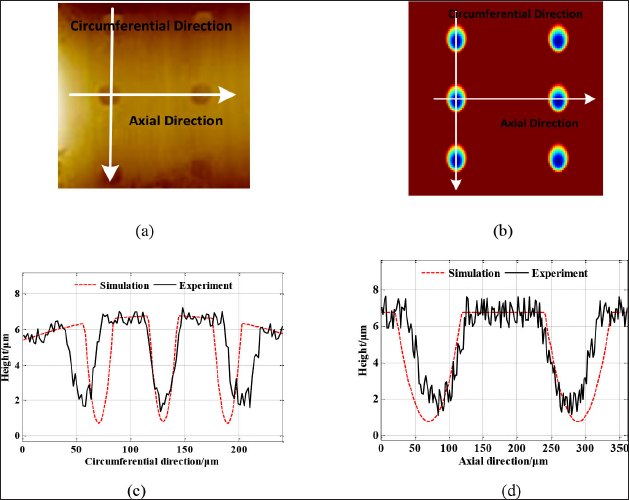
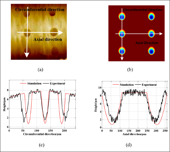
Comparison of surface topography with depth of cut 6 µm: (a) experimental topography, (b) simulation topography, (c) comparison in circumferential direction, and (d) comparison in axial direction.
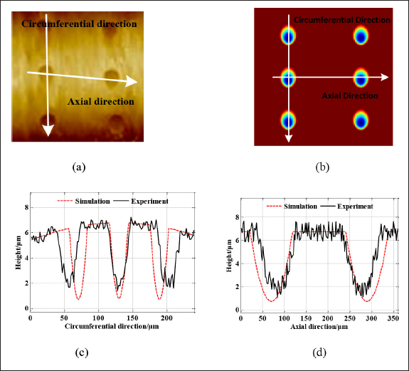
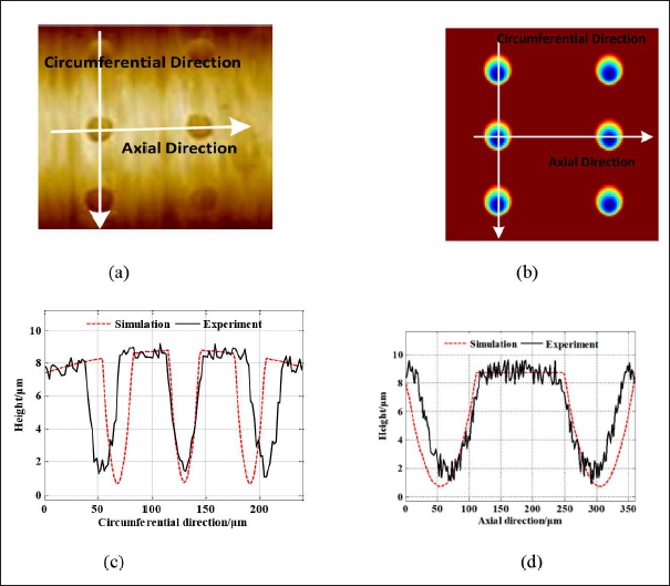
Comparison of surface topography with depth of cut 7 µm: (a) experimental topography, (b) simulation topography, (c) comparison in circumferential direction, and (d) comparison in axial direction.
Comparison of surface topography with depth of cut 8 µm: (a) experimental topography, (b) simulation topography, (c) comparison in circumferential direction, and (d) comparison in axial direction.
The comparison of surface topography with depth of cut 9 µm: (a) experimental topography, (b) simulation topography, (c) comparison in circumferential direction, and (d) comparison in axial direction.
Comparison of surface topography with depth of cut 10 µm: (a) experimental topography, (b) simulation topography, (c) comparison in circumferential direction, and (d) comparison in axial direction.
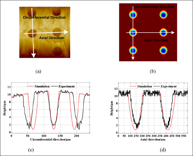
The details for the five groups of dimples along the circumferential and axial directions are also shown correspondingly in Figures 7–11 to display the surface topography more clearly. A comparison of micro-texturing height profiles between the simulation results and the actual experimental data for the two directions are given in images (c) and (d) of the figures. Apparently, similar waveforms were produced, and the shapes of adjacent dimples are close to those calculated with the developed model. The comparison with the achieved depth of dimples revealed that the depth of dimples had high accuracy in both simulations and experiments along the circumferential and axial direction with close surface topography of dimples obtained with the simulation and experiments. A detailed comparison of the parameters is given in section “Discussion”.
Discussion
Comparison of shape parameters
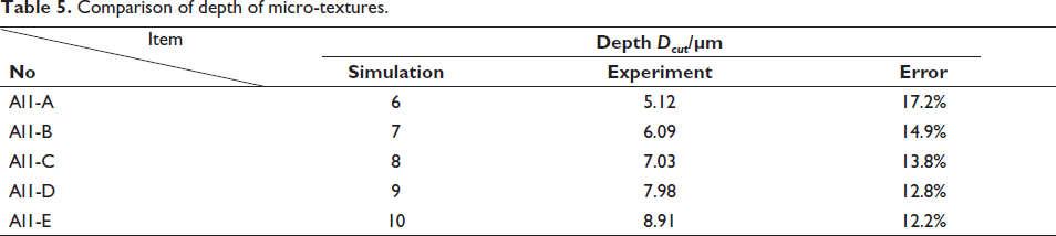
In order to have a better comparison, Table 5 lists the data for all the five studied micro-textures in terms of their depth, while Figure 12 gives the comparison of this parameter for simulation results and experimental data.
Comparison of depth of micro-textures.
Comparison of depth of micro-texture between simulation and experiment.
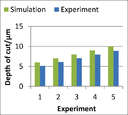
Apparently, the simulation results for the depth of micro-textures are higher than the experimental values. This can be explained by the fact that the established simulation model did not consider all the physical factors affecting the machining topography. As a result, some machining errors exist. It was observed that the error for the depth of the micro-texture was within 10%–20% and reduced with the increase in the vibration amplitude. The depth errors of five groups of dimples ranged from the minimum 12.2% to the maximum 17.2% (see Table 5).
A similar comparison was implemented for the circumferential length of micro-textures. It can be seen from Table 6 and Figure 13 that the error for this parameter was some 20% with the theoretical calculations providing lower estimates of the circumferential length than observed in the experiments. The magnitude of the error varied from a minimum of 18.8% to a maximum of 22.1% (Table 6). This difference is attributed to the influence of the tool nose arc, while the developed simulation model does not consider the influence of the tool nose arc.
Comparison for circumferential length.
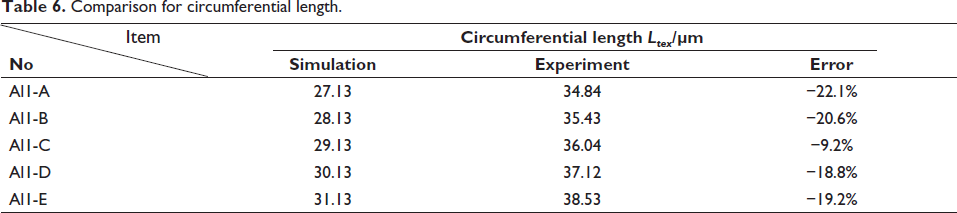
Comparison of circumferential length between simulation and experiment.
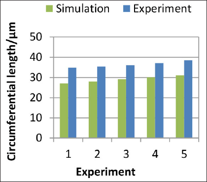
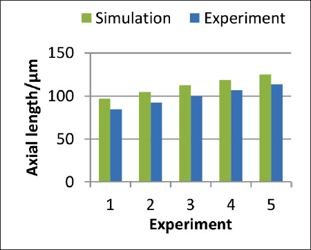
Table 7 presents the comparison of the axial length of micro-textures for machining parameters of Table 4 based on the comparison of Figures 7–11. Figure 14 gives the comparison of the axial length between simulation and experiment. It can be seen from Table 7 and Figure 14 that the experimental data were lower than simulation results, and errors for the circumferential length were within 15% when compared to the simulation based on the theoretical calculation results. The last column in Table 7 explains that the error of the axial length ranged from a minimum of 10.0% to a maximum of 15.1% and increased with the increase in the vibration amplitude (Table 7 and Figure 14). These differences are attributed to the influence of the tool nose arc on machining topography. It can be explained that the differences of axial length of dimple for simulations and experiments stemmed from the influence of tool nose arc and was related to the depth of the dimple.
Comparison of axial width.
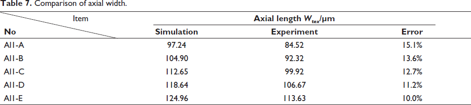
Comparison of axial width between simulation and experiment.
Comparison of distribution parameters
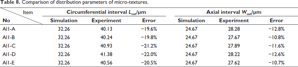
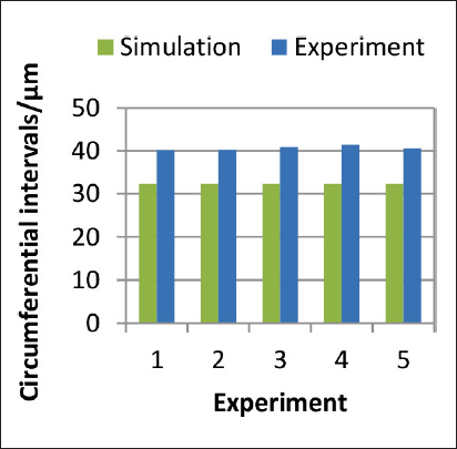
Another focus of the analysis was the spatial pattern of the micro-textures. Table 8 presents the comparison of distribution parameters for the machining experiments with the respective graphs given in Figure 16 for the circumferential and axial directions.
Comparison of distribution parameters of micro-textures.
Comparison of circumferential interval.
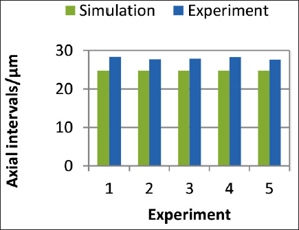
Comparison of axial interval.
Evidently, the error of intervals in the circumferential direction was approximately 20% between the results of theoretical calculation and the experimental data. This error was mainly induced by the overcut caused by the elliptical vibration cutting locus. Thus, the experimental data for the interval in the circumferential direction of the micro-texture were higher than the theoretically calculated results. It means that the increase in the spindle speed induced larger intervals in the circumferential direction. It can be also observed that the intervals in the circumferential direction of micro-textures showed low sensitivity to the vibration amplitude (Table 8). This conclusion agrees well with the theoretical analysis.
Considering the error for the interval in the axial direction of micro-textures, it is noticeably lower, some 10%, for simulation results. It also exhibits only some minor variation with the change in the vibration amplitude (Table 8). This conclusion agrees well with the theoretical analysis.
The presented comparison of theoretical and experimental results demonstrates that the developed control and simulation models for the micro-texture can be used to predict the micro-texture, generated in the UEVA process together with trends for different machining and vibration conditions. This also helps to understand the mechanism of elliptical vibration-assisted micro-texturing. Importantly, the accuracy of the machined micro-textures can be further improved by considering the compensation for the established control model. It can be implemented by adjusting the output of control parameters using the micro-texturing model, and this is planned as further work.
Conclusion
In this article, an UEVA cutting method based on the control parameter model is proposed to fabricate micro-textures on cylindrical surfaces together with the corresponding simulation model for prediction of the micro-texture topography. The following conclusions can be formulated from the present work:
The fabrication mechanism of UEVA cutting micro-texture is described and analyzed. The developed model allows the active control of the UEVA cutting locus to generate the required micro-texture. The simulation model of the generated micro-texture was formulated to predict the topography of micro-texture and implemented in the simulation software. The conducted cutting experiments on micro-texturing verified the developed control model. The comparison of theoretical and experimental results demonstrated that the proposed UEVA cutting micro-texture method provided good predictions and can be used to generate the micro-texture on the cylindrical surfaces.
Footnotes
Acknowledgment
This research was funded by the National Natural Science Foundation of China under grant no 51675277 and by High level Talents Project of “six talents summit” in Jiangsu Province of China under grant no GDZB-011.
Declaration of conflicting interests
The authors declared no potential conflicts of interest with respect to the research, authorship, and/or publication of this article.
Funding
The authors received no financial support for the research, authorship, and/or publication of this article.