
Abstract
Nitinol shape memory alloy (SMA) has outstanding chemical and mechanical properties which make the machining of Nitinol SMA more difficult than other materials due to super-elasticity and multiphase transformation. Wire electrochemical machining (WECM) is a nontraditional process, which removes conductive material through anodic dissolution despite of material’s properties. In this paper, the mathematical model is presented for slit width calculation for the influence of different parameters using vibration-assisted nozzle jet flushing. In this experimental investigation, the effect of prominent energy input parameters on wire feed rate to achieve better homogeneity, machining accuracy, and surface quality with a 300 µm thick sheet of Nitinol SMA micro-slits has been presented using an in-house developed WECM set-up. Experimental results revealed that the wire feed rate and surface roughness drastically increases with an increase in the most influencing energy input parameter, that is, pulse voltage with minimum average surface roughness (Ra) of 0.1076 µm and 123.60 µm average slit width at 7 V pulse voltage. Finally, the curved complex micro-feature of a 120 µm thick sheet of Nitinol SMA was fabricated successfully with a 137.795 µm average slit width under the controlled process parameter combination using WECM.
Introduction
The prerequisite behind reducing the size of components is motivated by the objective of saving resources in terms of energy, material, and space. In the modern era, this objective is being highly prioritized by industrialists, academicians, and researchers from a development and application point of view. The increasing use of these micro-sized products has resulted in the evolution of new machining methods. The micro-machining describes as one of the machining methods where an unwanted material is removed in micro-dimensions from the work material to obtain the microfeatures. However, the parallel development of new materials is also a challenge for micro-machining processes to produce precise components. In this context, several developments in the machining processes have come into existence over the different phases in the last few years. The micro-structures after the wire electrochemical machining (WECM) operation were free from recast layers, craters, and micro-pores. The formation of an oxide layer on a machined conventional ECM process limits the current flow across the circuit. Consequently, no further electrolytic dissolution of material takes place. Thus, there is a need to remove this oxide layer for maintaining the process continuity
At present, the factor restricting WECM is the machining instability caused by dissolved electrolysis products and sludge removal on the surface near the machining zone. According to Bhattacharyya, high machining accuracy and surface quality can be obtained by optimizing and managing input process parameters during WECM.
1
Zadafiya et al. studied that the use of SMA’s is restricted due to several unusual thermal effects.
2
Sharma et al. reviewed and concluded that WECM is established to be a feasible process for difficult-to-cut conductive material machining.
3
The experimental investigation of the TiAl alloy machining utilizing axial electrolyte flow WECM is presented by He et al.
4
The influence on the side gap of the vibrating workpiece with traveling wire parameters and uniformity of micro-slits during WECM was examined by Qu et al.
5
To expedite mass movement and improve dissolution localization, Xianghe et al. employed a vibratory ribbed instrument. When a ribbed tool was used instead of a smooth wire tool, the width of the machined incision was lowered.
6
To increase machining efficiency, He et al. used multi-wire electrodes assisted with vibration and high traveling speed, which they tested using produced microstructures.
From the literature review and initial experimental results, it can be inferred that WECM can effectively machine hard work materials with good surface integrity. The machining strategy offers remarkable advantages such as superior machining accuracy and improves surface integrity of machine components. Therefore, this paper emphasizes the investigation of the influence of energy input parameters on wire feed rate and surface characteristics of Nitinol SMA during WECM. The effect of important energy input parameters, that is, pulse voltage, pulse frequency, and duty ratio on wire feed rate and the machining accuracy is studied and fabricated fine microfeatures. Also, the WECM process is conducted to investigate the surface characteristics by measurement of surface roughness associated with the most influencing energy input parameter, i.e., pulse voltage, and analyzed the changes in composition through EDS and SEM of the machined micro-slit.
Modeling of WECM
Figure 1a illustrates the principle of the WECM process. The wire acts as the cathode traveling along its axis and the workpiece acts as an anode submerged in an electrolyte. The micro-slits are fabricated by controlling the workpiece feed path and the electrolyte is enforced to flow through the narrow inter-electrode gap (IEG) with the help of an axial nozzle jet flow system assisted with PZT vibration. The schematic of the side gap for micro-slit width is shown in Figure 1b.
(a) WECM principle and (b) schematic of side gap for micro-slit width.
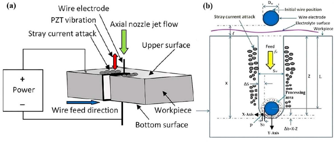
The wire electrode of diameter Dw is fed towards the workpiece at fw wire feed rate with an initial IEG
Though the current in anode and cathode material is the same, current densities in anode and cathode are different which can be defined as the ratio of current to the area normal to the direction of flow of the current. There are two possible directions of the flow of current. In the axial direction, it may be downwards or upwards. In this direction, the current density remains similar throughout the height due to the same cross-sectional area. In the radial direction, the area normal to this axial direction of flow of current is the surface area. The surface area is minimum at the inner surface (frontal gap in the direction of machining zone) and maximum at the outer surface (back side of wire) and changes with workpiece thickness due to the height of the workpiece. As the surface area changes, the current density also changes with the thickness. It is maximum on the inner surface and minimum on the outer surface.
In the electrolytic process, the current density

where
The expression for effective electrolyte conductivity considering the effect of gas bubbles with dissolution hydroxide sludge produced during electrolysis product is given by
16
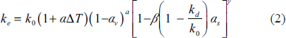
where

where
The anodic dissolution process is interrupted because of the less current density near the machining zone with reduced electrolyte conductivity. As per Faraday’s laws, material removal is
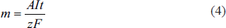
where
Equation (4) can be re-written as
where
Now, it is well known that
where
Neglecting the effect of electrolyte temperature and bubbles during machining, electrolyte, and electrolysis product mixture conductivity can be re-written as
17
where

where
The pump output flow and velocity are

where
As the electrolyte is flowing along a pipe with decreasing nozzle radius, an equal quantity of fluid should flow past any point in the pipe and nozzle in a specified time to make sure continuity of flow. In this case, the velocity must necessarily increase due to decreased nozzle diameter. Therefore, the flow rate must be the same at all points, that is, pump output volume flow qp and flow rate of nozzle jet flow qn equal.
The equation of continuity for electrolyte flowing through the pump output mouth and nozzle jet is

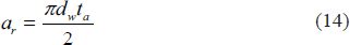
where
It can be seen that the area of the wire
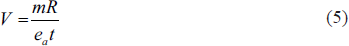
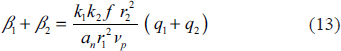
From the geometry of the machined slit, the mass removed in the process can be determined as
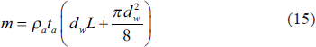
where
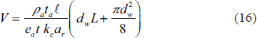
From Equations (5), (6), and (15), applied pulse voltage can be re-written as
The equation of frontal IEG is
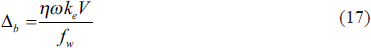
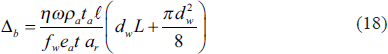
where
where

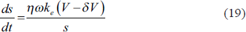
From Equations (17) and (20), it can be re-written as

Integrating Equation (21)
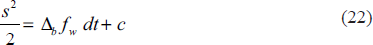
When
When the wire diameter is at a micron scale,

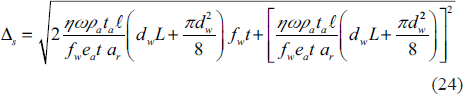
Slit width
This empirical formula as developed will be useful for estimating the slit width considering the influence of different process parameters in WECM.
Experimental setup
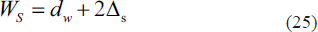
In the present study, an in-lab developed WECM setup was used to perform the experiments and the schematic view is shown in Figure 2. The stage and controller system equipped for three-axis positioning has been used for machining operations and the machining chamber was mounted on the platform. POA75-4 ultra-high-speed bipolar pulse generator was used as a power source. Electric pulses were applied between an anodic Nitinol SMA workpiece immersed in the electrolyte solution and a PTFE tube insulated wire electrode which was held vertically straight with suitable tension. The electrolyte systems consist of an electrolyte tank and pump which flows pressurized electrolyte on a machined surface through the nozzle.
In-house developed WECM setup.
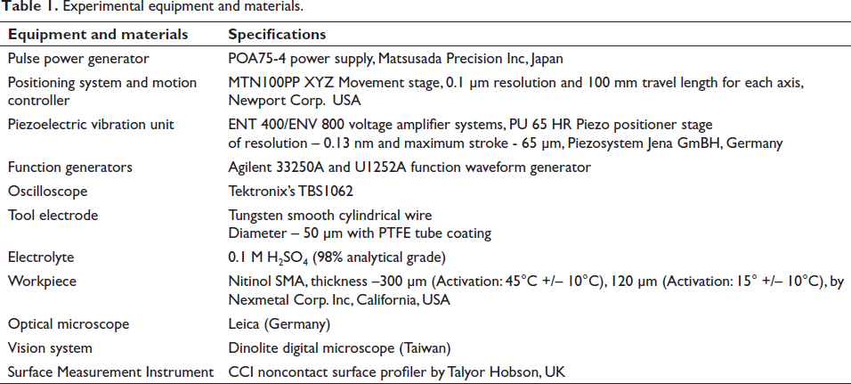
The PZT vibration unit was used to regulate frequency and amplitude for the appropriate PZT positioning and acts as a flushing system for the renewal of fresh electrolytes. The vision system for monitoring the machining process was also used to conduct the research. Table 1 shows the specifications of the experimental equipment and material for WECM.
Experimental equipment and materials.
Experimental planning
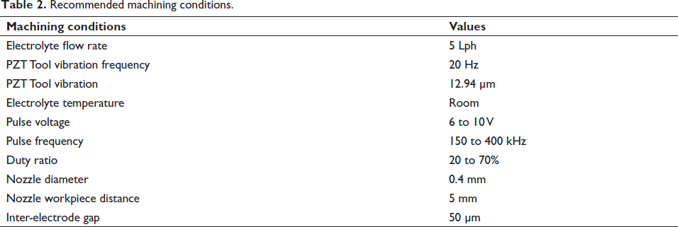
During experiments, a tungsten microelectrode (cathode) in the form of straight smooth cylindrical wire of Ø50 µm (mfg. by Goodfellow Ltd, UK) is used. The Nitinol workpiece specimens were 300 µm thick sheet for investigating energy input parameter effects on wire feed rate and 120 µm thick sheet for fabricating complex curved micro-features to the effect of thickness of material with specimen size of 10 mm × 10 mm × 0.12 mm has been used. All the experiments are planned with equipment and material detailed in Table 1 by maintaining 50 µm initial IEG using a developed vibration-assisted axial nozzle jet flow WECM experimental setup. 18 The experiments were planned to investigate the influence of prominent parameters for energy interaction behavior during the fabrication of micro-slits for better homogeneity, and machining accuracy of Nitinol SMA machined micro features during WECM. Table 2 shows the recommended machining conditions chosen as per past research experiences for the experimentations to fabricate Nitinol SMA microfeatures.
Recommended machining conditions.
Each experiment has been conducted a minimum of three times using different ranges of parameters selected from the previously published literature and machined Nitinol micro features dimensions were measured using Leica optical microscope and the Taylor Hobson CCI instrument has been used for surface roughness measurement. Further, micro-structural analysis of the machined surface was conducted through scanning electron microscopy (SEM), and energy-dispersive X-ray spectrum (EDS).
Results and discussion
To detect the influence of different energy input parameters, that is, pulse voltage, pulse frequency, and duty ratio on wire feed rate, machining accuracy, and surface characteristics, the experimental observations have been discussed hereunder.
Influence of pulse voltage on wire feed rate and machining accuracy
The theoretical study from the developed mathematical model predicts that as the wire feed rate increases, the slit width and secondary electrolysis will decrease. However, the wire feed rate has an upper limit in specific conditions during actual machining, because of the restriction of mass transfer. All the experiments have been carried out using 250 kHz pulse frequency and 50% duty ratio with a wide range of varying pulse voltages from 6 to 10 V.
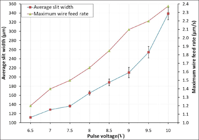
It can be seen that the maximum achievable wire feed rate increases with an increase in applied voltage because an increase in applied voltage increases the current in the circuit, the amount of electricity passing through per unit time, the amount of anode material dissolution, and the frontal and side gap. Experiments are designed to investigate the influence of pulse voltage on the maximum achievable feed rate and slit width as shown in Figure 3. The maximum 2.4 µm/s wire feed rate has been achieved at 10 V pulse voltage with 342 µm average slit-width. It shows that even though the wire feed rate increases with pulse voltage, overcut of the slit width also increased. However, the increase of applied voltage will also increase the electrolysis products produced per unit of time, and it leads to a short circuit if the machining gap becomes tiny, which limits the further increase of wire feed rate. For this reason, it can be observed that when the applied voltage increases above 10 V, the maximum achievable wire feed rate does not continue to increase at this condition. Although the slit width is the smallest, that is, 111 µm when the voltage is 6.5 V, the secondary corrosion of the sidewall is serious and the homogeneity of the slit sidewall is poor because the wire feed rate is too small. Therefore, considering the WECM efficiency, localization, homogeneity, and machining accuracy, 7 V is selected as the appropriate voltage parameter and the minimum average slit width of 128 µm has been fabricated at 1.4 µm/s wire feed rate.
Influence of pulse voltage on wire feed rate and machining accuracy.
Influence of pulse frequency on wire feed rate and machining accuracy
The influence of pulse frequency on wire feed rate and slit width in the WECM process has been carried out using 7 V pulse voltage and 50% duty ratio with a varying pulse frequency of 150 to 400 kHz and the observed results are graphically represented as shown in Figure 4. It is revealed that the pulse frequency below 200 kHz has a very poor dissolution rate resulting in poor machining with a reduced wire feed rate and a higher pulse frequency above 400 kHz has a higher feed rate resulting in micro sparks during machining due to reduced IEG and produces poor machining accuracy.
Influence of pulse frequency on wire feed rate and machining accuracy.
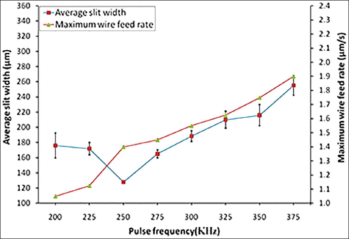
Also, it is observed that the maximum attainable feed rate decreases from 1.4 to 1 µm/s with the increase of the pulse frequency from 250 to 200 kHz. This is because the increase in the pulse frequency reduces the pulse period. When the duty cycle is constant, the effective machining time per unit time decreases. Also, it is observed that the pulse frequency from 250 to 375 kHz shows a linear increase in wire feed rate. The maximum 1.9 µm/s wire feed rate has been achieved at 375 kHz pulse frequency above which no further dissolution takes place and machining of Nitinol SMA has been stopped because of short-circuits and heavy micro-sparks due to high wire feed rate and current density in the machining area. The maximum attainable wire feed rate is decreased as a result of less anode material dissolution and a smaller machining gap. But when the frequency is too low, the same duty cycle will result in a more effective machining time per unit time. Although the maximum wire feed rate is now somewhat higher, the increase in wire feed rate is simultaneously constrained by the rise in electrolysis product by the anodic dissolution rate. Therefore, while making sure that the maximum wire feed rate is not drastically decreased, a greater pulse frequency should be chosen taking into account the WECM efficiency, homogeneity, and machining accuracy.
Influence of duty ratio on wire feed rate and machining accuracy
The effect of duty ratio on wire feed and slit width using 7 V pulse voltage, 250 kHz pulse frequency with 20%−70% duty ratio in the WECM process is shown in Figure 5. It can be observed that the maximum achievable wire feed rate increases with the increase in duty ratio, which is due to the increase in effective machining time, the increase of average machining current, the increase of anode material erosion, and the increase of machining gap, so the maximum achievable wire feed rate increases. Similarly, it can be observed from the curve that the increase rate of wire feed rate increases with the increase in duty ratio, which is opposite to the trend of an increasing rate of slit width. It shows that the increase in duty ratio increases the production of electrolytic products per unit of time, which makes machining stability worse and limits the increase of feed rate.
Influence of duty ratio on wire feed rate and machining accuracy.
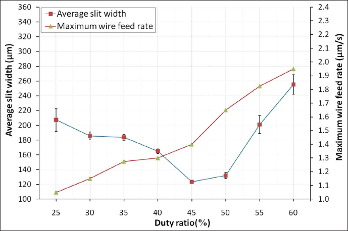
From the machining results, it can be observed that under the faster wire feed rate, the slit width is still increased when the duty ratio is from 50% to 60%, and the slit homogeneity and machining accuracy are poor, therefore, to obtain higher machining accuracy and better slit morphology, a smaller duty ratio should be chosen. When the duty ratio is from 25% to 40%, the decrease in the etching rate will significantly reduce the maximum achievable wire feed rate and very poor or no dissolution takes place at a 20% duty ratio. The average slit width of 207 µm at a 25% duty ratio and a maximum average slit width of 255 µm at a 60% duty ratio has been obtained. However, the minimum average slit width of 123 µm has been obtained at a 45% duty ratio. Therefore, considering the WECM efficiency, localization, and slit quality, 45% is selected as the appropriate duty ratio parameter.
Micro-slits at (a) 7 V, 250 kHz, 45%, (b) 8 V, 300 kHz, 25%, and (c) 9 V, 350 kHz, 50%.
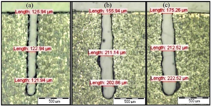
Nitinol SMA micro-slits with different combinations of pulse voltage, pulse frequency, and duty ratio as shown in Figure 6. It is observed that the micro-slit fabricated with a parameter combination of 7 V pulse voltage, 250 kHz pulse frequency, and 45% duty ratio achieved better machining accuracy with minimum slit width as compared to micro-slits machined at a combination of 8 V, 300 kHz, 25%, and 9 V, 350 kHz, 50%. Furthermore, it has been observed that the slit width has been increased drastically with higher pulse voltage and pulse frequency with poor homogeneity and machining accuracy as shown in Figure 6c. The overcut has been greatly reduced and a straight micro-slit has been fabricated at 7 V pulse voltage, 250 kHz pulse frequency, and 45% duty ratio as shown in Figure 6a. Also, it is seen that the use of a very low duty ratio, that is, 25% affected machining accuracy and homogeneity to a large extent due to the uncontrolled machining process as shown in Figure 6b.
Influence of pulse voltage on surface roughness of Nitinol SMA micro-features
The surface roughness has a direct relation with the pulse voltage. The surface roughness of 300 µm thick Nitinol SMA at 0.1M H2SO4 electrolyte concentration after machining at 250 kHz pulse frequency, 45% duty ratio, and different pulse voltages varying from 7 to 10 V are shown in Figure 7. An increase in pulse voltage applied increases the surface roughness due to a rise in the anodic dissolution rate. At higher pulse voltage coupled with electrolyte concentration, the electrolyte action increases resulting increase in material removal rate (MRR). As the MRR increases, a poor surface finish will be obtained in the machining process. If the potential difference between the wire and workpiece is very high, then poor surface roughness can be achieved from the Nitinol SMA. At low pulse voltage below 7 V, machining accuracy is very poor but surface roughness is better at low pulse voltage up to 7 V. The surface finish was smoothly reduced with the increase in pulse voltage above 8 V and finally, poor surface roughness occurred for further increases in pulse voltages up to 10 V. The machining accuracy has been greatly improved at 7 V with an increase in surface finish.
Nitinol surface microstructure at pulse voltages: (a) 7 V, (b) 8 V, (c) 9 V, and (d) 10. V.
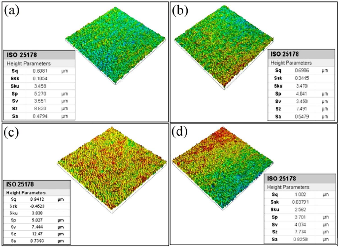
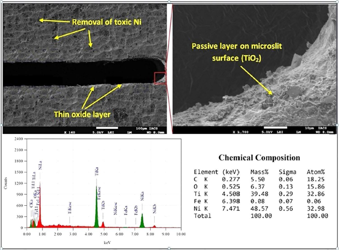
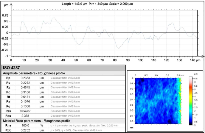
The surface roughness (Sa) at 7 V was 0.4797 µm which is further increased to 0.8258 µm at the maximum pulse voltage level, i.e., 10 V. The EDS analysis was carried out for the micro-slit machined at 7 V pulse voltage, 250 kHz pulse frequency, and 45% duty ratio to identify the composition of Nitinol SMA after machining as shown in Figure 8. It is seen that the mass of oxygen (O) has been increased to 6.37% after machining which shows the formation of a thin protective passive layer of TiO2 on the surface of the micro-slit. Also, the increase in 5.50% mass carbon after machining shows that it oxidizes away the toxic carbon monoxide or carbon dioxide. Further, a decrease in Ni mass from 56% to 48.57% shows the removal of more toxic Ni atoms. The minimum average surface roughness (Ra) of the machined micro-slit has been measured as 0.1076 µm as shown in Figure 9. It shows that the WECM is capable of producing complex micro-features on any difficult-to-cut conductive material with a higher surface finish compared to other nonconventional machining processes.
SEM and EDS analysis of Nitinol SMA micro-slit.
Surface roughness of Nitinol SMA micro-slit at 7 V pulse voltage.
Fabrication of complex curved micro-feature of Nitinol SMA
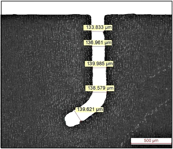
After successfully identifying the effect of prominent energy input parameters on wire feed rate for obtaining a better machining accuracy and surface quality, 7 V pulse voltage, 250 kHz pulse frequency, 1.4 µm/s wire feed rate, 45% duty ratio has been used and a homogeneous complex curved micro-feature has been successfully fabricated on 120 µm thick Nitinol SMA as shown in Figure 10. Nitinol SMA and the requirement of energy input increases with an increase in workpiece thickness to obtain minimum overcut and better surface quality during WECM.
Curved complex micro-feature of Nitinol SMA.
Conclusions
This research work presented a mathematical model and experimental investigation into the effect of prominent energy input parameters, that is., pulse voltage, pulse frequency, and duty ratio on wire feed rate for homogeneity, machining accuracy, and surface characteristics of Nitinol SMA micro-slits and concluded as follows:
Experimental results showed that when the applied voltage increases above 10 V, the maximum achievable wire feed rate does not continue to increase above 2.4 µm/s. Although the slit width, that is, 111 µm is the smallest when the voltage is 6.5 V, the secondary anodic dissolution of the sidewall has a more adverse effect on machining and the surface quality of the slit sidewall is poor because the wire feed rate is too small. Therefore, 7 V is selected as the appropriate voltage parameter and the minimum average slit width of 128 µm has been fabricated at 1.4 µm/s wire feed rate with minimum surface roughness (Sa) was 0.4797 µm which is further increased to 0.8258 µm at 10 V. The average surface roughness (Ra) of the machined micro-slit has been measured as 0.1076 µm at 7 V pulse voltage. It can be observed that the maximum achievable wire feed rate decreases from 1.4 to 1 µm/s with the increase of the pulse frequency from 250 to 200 kHz. Also, the pulse frequency from 250 to 375 kHz shows a linear increase in the wire feed rate. The maximum 1.9 µm/s wire feed rate has been achieved at 375 kHz pulse frequency. When the duty ratio is constant, the effective machining time per unit time decreases. The average slit width of 207 µm at a 25% duty ratio and a maximum average slit width of 255 µm at a 60% duty ratio has been obtained. However, the minimum average slit width of 123 µm has been obtained at a 45% duty ratio. It is observed from EDS analysis that the mass of oxygen (O) has been increased to 6.37% after machining which shows the formation of a thin protective passive layer of TiO2 on the surface of the micro-slit. Also, an increase in 5.50% mass carbon after machining shows that it oxidizes away the toxic carbon monoxide or carbon dioxide. Further, a decrease in Ni mass from 56% to 48.57% shows the removal of more toxic Ni atoms. It shows machined surface has no undesirable effects after WECM. After successfully identifying the best energy input parameter combination amongst others, a parametric combination of 7 V pulse voltage, 250 kHz pulse frequency, 1.4 µm/s wire feed rate, and 45% duty ratio, Nitinol SMA homogeneous complex curved micro-feature has been successfully fabricated with 137 µm average slit width during WECM of 120 µm thick Nitinol SMA. It shows that the requirement of energy input increases with an increase in workpiece thickness to obtain minimum overcut.
The scope of this research is to understand the effect of energy input parameters on the wire feed rate and surface characteristics during the machining of Nitinol SMA during WECM. However, more research is needed for the validation and analysis of different process parameters using different optimization and machining techniques for the fabrication of industrially applicable Nitinol SMA complex microfeatures during WECM.
Footnotes
Acknowledgments
The authors acknowledge the financial support from SERB, DST New Delhi, India, for conducting the research work (Grant No. SB/S3/MMER/0056/2014).
Declaration of Conflicting Interests
The authors declared no potential conflicts of interest with respect to the research, authorship, and/or publication of this article.
Funding
The author received no financial support for the research, authorship and/or publication of this article.