
Abstract
Aside from modeling geometric shape, three-dimensional (3D) urban procedural modeling has shown its value in understanding, predicting and/or controlling effects of shape on design and urban planning. In this paper, instead of the construction of flood resistant measures, we create a procedural generation system for designing urban layouts that passively reduce water depth during a flooding scenario. Our tool enables exploring designs that passively lower flood depth everywhere or mostly in chosen key areas. Our approach tightly integrates a hydraulic model and a parameterized urban generation system with an optimization engine so as to find the least cost modification to an initial urban layout design. Further, due to the computational cost of a fluid simulation, we train neural networks to assist with accelerating the design process. We have applied our system to several real-world locations and have obtained improved 3D urban models in just a few seconds.
Introduction
Three-dimensional (3D) urban modeling has gained more and more research attention in last decades. Besides modeling geometric shape, urban modeling has shown its research value in understanding, predicting and/or controlling effects of shape on many urban concerns such as urban planning (e.g. Vanegas et al., 2012; Weber et al., 2009), urban vehicular traffic (e.g. Garcia-Dorado et al., 2014; Sewall et al., 2011), crowd simulation (e.g. Feng et al., 2016), urban weather simulation (e.g. Garcia-Dorado et al., 2017) and water/fluid simulations (e.g. Bridson, 2015; Enright et al., 2002). In this paper, we establish a link between geometric urban layout design and urban flooding, assist in designing improved flood-sensitive cities, and generate more realistic simulations of flooding in an urban environment.
For several decades, structural flood protection measures such as levees, dams and dikes have been widely used to control floods. These measures have been criticized because they often interrupt natural flooding processes by removing natural land cover, reduce natural water storage capacity and disrupt water flow paths (Lennon et al., 2014; O’Neill, 2013). In the recent years, there is a shift in focus from hard flood controls towards a more strategic approach characterized by mitigating flood risk and increasing resilience during the urban design process (Lennon et al., 2014; White, 2008). In particular, several soft solutions have been introduced at different spatial scales ranging from regional scale to building scale. For example, storing water in farmland, where the land remains property of the farmer and is used for temporary water storage in extreme flooding (Fokkens, 2006). Other case-studies relocate the most sensitive land-use types; e.g. suggest moving residential areas to zones with a lower flood risk (Satterthwaite, 2007). However, the natural advantages of the floodplain and the trend towards urban densification and expansions has fomented that floodplain development continued apace, regardless of potential planning policies to control these factors (Moel and Aerts, 2010; Mustafa et al., 2018; White, 2008). Consequently, the potential damages as a result of floods will continue to rise. Within this context, digitally enhanced urban design has the potential to construct flood resistant urban patterns.
Within computer graphics and geometric modeling, existing tools model either fluid simulation, which has a long history in computer graphics (e.g. Bridson, 2015; Enright et al., 2002; Losasso et al., 2004) or geometric modeling (e.g., forward procedural modeling (Müller et al., 2006; Vanegas et al., 2009), and inverse procedural modeling (Demir et al., 2015; Vanegas et al., 2012)).
Our key motivation is to create a procedural generation system that automatically generates 3D urban layouts that consider the influence of geometric urban characteristics (e.g. road width, orientation, curvature, etc.) on flow properties during flood water simulations (and in reality) (Figure 1). The urban model layout influences the distribution of water discharges between roads as well as the flow depths and velocities. In a sense, we explore urban geometric grammars that help reduce flooding: i.e. what urban design rules produce a passive barrier against natural floods? Our methodology is concerned with accommodating the unavoidability of floods by pre-emptive modifications to urban design. Designing and evaluating different urban layouts in terms of flood damage requires considerable time and resources. Any effort to reduce the design time or required resources is a profitable investment. Visual computing design tools, such as ours, can greatly help urban designers and architects assess the implications of different design decisions on expected flood damage, reduce design time, and produce practical urban patterns.
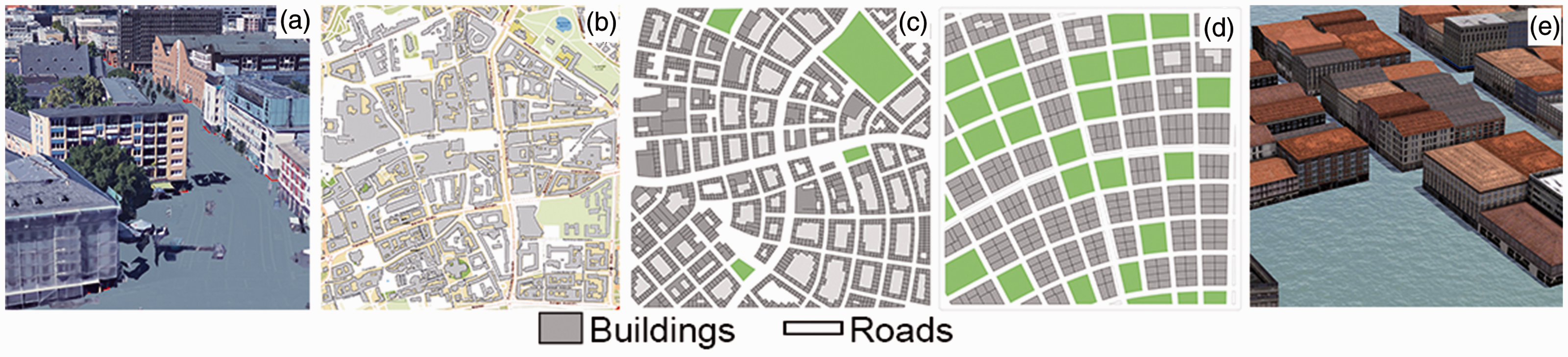
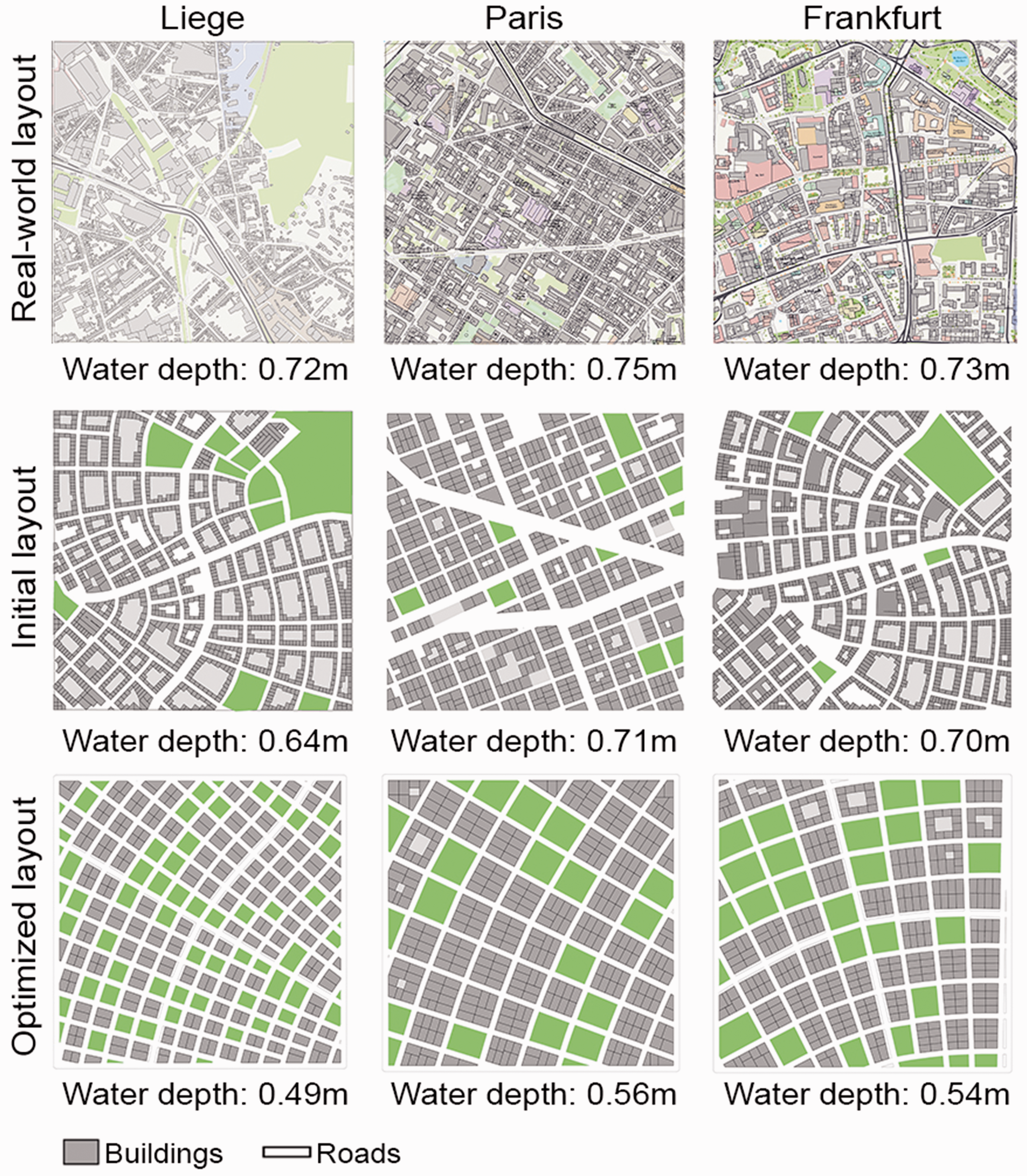
Flood-sensitive urban layouts. We introduce a procedural urban design system that reduces flood water depth based on the geometrical characteristics of an urban layout. The user sets desired parameter values or building coverage, then our system optimizes the initial layout to reduce flood water depth. In this example, a layout in Frankfurt ((a) and (b)) shows an average water depth of 0.73 m and (c) is the initial layout which produces a simulated flood water level within 0.03 m of the actual layout’s. The optimized layout ((d) and (e)) reduces the water level by 0.19 m (26%). All layouts retain the same building coverage.
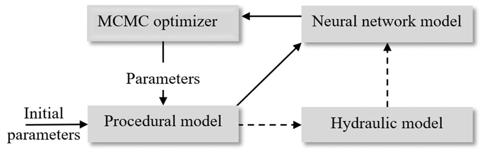
Our proposed interactive and automatic approach consists of four components (Figure 2). First, we represent an urban area by dividing it into representative cells, typically 1 × 1 km. For each cell, we define a parameterized procedural model that can generate a wide range of possible urban layout configurations which mimic actual real-world urban patterns. Second, a porosity-based hydraulic model computes the water flow characteristics of a proposed urban layout cell. Third, to yield an interactive design process, we approximate the relationship between urban layout and flood flow characteristics with a trained neural network (NN). Fourth, we provide an inverse modeling engine to suggest the best urban layout that yields desired building coverage – the area of buildings at ground level divided by the area of the entire cell and expressed as a percentage – and water depth.
System pipeline.
Our major contributions include:
a parameterized procedural urban model of the urban layout within a 1 km2 area controlling road network, blocks, parcels, and buildings geometries; integrating our procedural urban model with a porosity-based hydraulic model that computes the water flow characteristics based on 2D shallow-water equations; and an optimization-based and NN-based inverse-modeling engine that can interactively propose the optimal urban layout to satisfy a specified reduction in flood water depth while maintaining a specified building coverage.
We have implemented our approach in many virtual urban layouts as well as three real-world cases located in Liege (Belgium), Paris (France), and Frankfurt (Germany).
Previous work
Our work builds on flood flow modeling within urban areas as well as forward and inverse procedural modeling. Floods claim many lives and cause major economic losses. A recent report by the UN, entitled “Human Cost of Weather Related Disasters”, shows that 157,000 people have died as a result of floods between 1995 and 2015. Additionally, floods damages cost US$104 billion/year globally according to the UN report “Global Assessment Report on Disaster Risk Reduction”. The magnitude and occurrence of flooding probability in many areas are currently increasing (Moel and Aerts, 2010; Pfister et al., 2004). Indeed, flood risks affect the day-to-day concerns of households, economic sectors and local governments in many areas around the world. Flood depth reductions, even if mild, can have a huge impact. For example, if the expected water height during a flood is 1.2 m referenced to ground level, installing polymer treated lumber panels may be necessary. If inundation water depth decreased by 20%, then at city or country-scale the resulting savings will be very significant.
3D models have been employed for assessment and visualization of urban flood flow and characteristics. Mioc et al. (2012) used observed data to generate 3D city models and integrated them with an inundation model. This integrated model helps city managers determine unsafe buildings and infrastructure in case of flooding. Amirebrahimi et al. (2016) proposed an integrated framework to measure flood damage to buildings based on a detailed 3D building information model. More related to our work is the work proposed by Christensen (2016) who introduced a dynamic approach to understanding the effect that natural disaster emergencies can generate in urban areas, with a particular emphasis on flooding events in residential areas. This approach also enables the end-user to simulate multi-scenarios based on different flood or water levels and to evaluate the impact of policy or structural interventions on reducing flood damages using an interactive interface. However, the objective disregarded the impact of urban layout configurations on flood damage.
Prior literature on geometric urban modeling for flood-sensitive urban areas has tended to focus on architectural design and general site layout recommendations (e.g. Lennon et al., 2014; Watson and Adams, 2010; White, 2008). The adaptation measures presented in these literatures include usage of wet-proofing, construction based on elevated ground, building on stilts, using temporal flood defenses, increasing urban green areas and increasing the distance between buildings and water bodies. Existing literature did not make a comprehensive analysis to identify the relationship between urban layout parameters and flood damage such as geometrical arrangement of road network, parcels, and buildings. Nonetheless, computational approaches such as ours can play a distinctive role in urban geometric design and flood damage assessment.
There are already existing models that enable urban designers to procedurally alter and explore urban configurations. An in-depth review of urban procedural modeling can be found in Kelly and McCabe (2017), Smelik et al. (2014), Vanegas et al. (2009), and Watson et al. (2008). Parish and Müller (2001) introduced a system to model cities using a procedural approach based on L-systems. Aliaga et al. (2008) proposed an interactive example-based approach that synthesizes urban patterns based on procedural modeling and image-based modeling. Vanegas et al. (2009) tackled an interdisciplinary research problem which considers modeling of behavioral and geometrical aspects of cities interactively. Yang et al. (2013) applied an optimized hierarchical splitting method to design urban layout automatically and interactively. Vanegas et al. (2012) proposed an inverse procedural system to generate urban 3D models according to several high-level parameters, such as average distance from buildings to closest parks and sun exposure, which motivate our work. While their approach uses a black-box procedural modeling, we explicitly define a set of parameters for our procedural modeling engine to make it suitable for training the NNs with a constant number of output values. In addition, we use a tensor field approach (Chen et al., 2008) to support a wide variety of road structures, which is crucial to increase the variation of the urban layouts.
The work of Whiting et al. (2009) is one of the first examples of iterative adjusting a procedural model's parameters to meet some design constraints. A range of later examples exist as well, such as the iteratively adjusted procedural model of Talton et al. (2011) who used Markov Chain Monte Carlo (MCMC) optimization to guide a procedural model to produce a geometric shape that conforms to a specification and, more recently, Garcia-Dorado et al. (2017) explore how to alter an urban design so as to yield a desired local weather pattern.
Compared to previous work, a major differentiation of our work is providing a computer system that integrates geometric rules and water flow assessment in order to provide urban layout designs that reduce flood water depth considering only changes to the urban geometrical configuration.
Methodology
Figure 2 provides a summary of our system pipeline. The system consists of four main modules (i) parameterized procedural urban model, (ii) a porosity-based hydraulic model that computes the water flow characteristics, (iii) an NN that used to compute hydraulic simulation, for a reason of speed, and (iv) an MCMC optimization-based inverse-modeling engine that can interactively propose the optimal urban layout.
The hydraulic model is used to train an NN to accelerate performance. Our hydraulic model focuses on river-based flooding scenarios. Although the dynamics of flooding vary with terrain, characterized by varying degrees of slope (Kirkby et al., 2002; Meraj et al., 2015), we do not consider slope in our current implementation. The two main reasons for this assumption include (1) many floodplain areas across the globe are relatively flat (e.g. Berthelot et al., 2015; Csiro, 2000) and (2) slope could lead to underestimating the effect of urban geometry changes.
Our flooding depth simulations are performed by WOLF 2D model (Erpicum et al., 2010). WOLF 2D is widely implemented to compute flood damages in urban areas (e.g. Beckers et al., 2013; Bruwier et al., 2015; Ernst et al., 2010). In 2003, WOLF 2D was selected by Wallonia (Belgium) authorities to perform all detailed 2-D flow simulations to produce official inundation maps, including in the framework of the European Floods Directive (Arrault et al., 2016). WOLF 2D solves the fully 2D shallow-water equations on Cartesian grids based on a conservative finite volume scheme with a flux vector splitting technique (Erpicum et al., 2010). To make more practical the training time of our NN, we accelerate the computational performance of this model by using a lower resolution mesh. Then, to compensate for the lower-resolution we include an anisotropic porosity model (Bruwier et al., 2018) to yield more accuracy.
Parameterized urban model
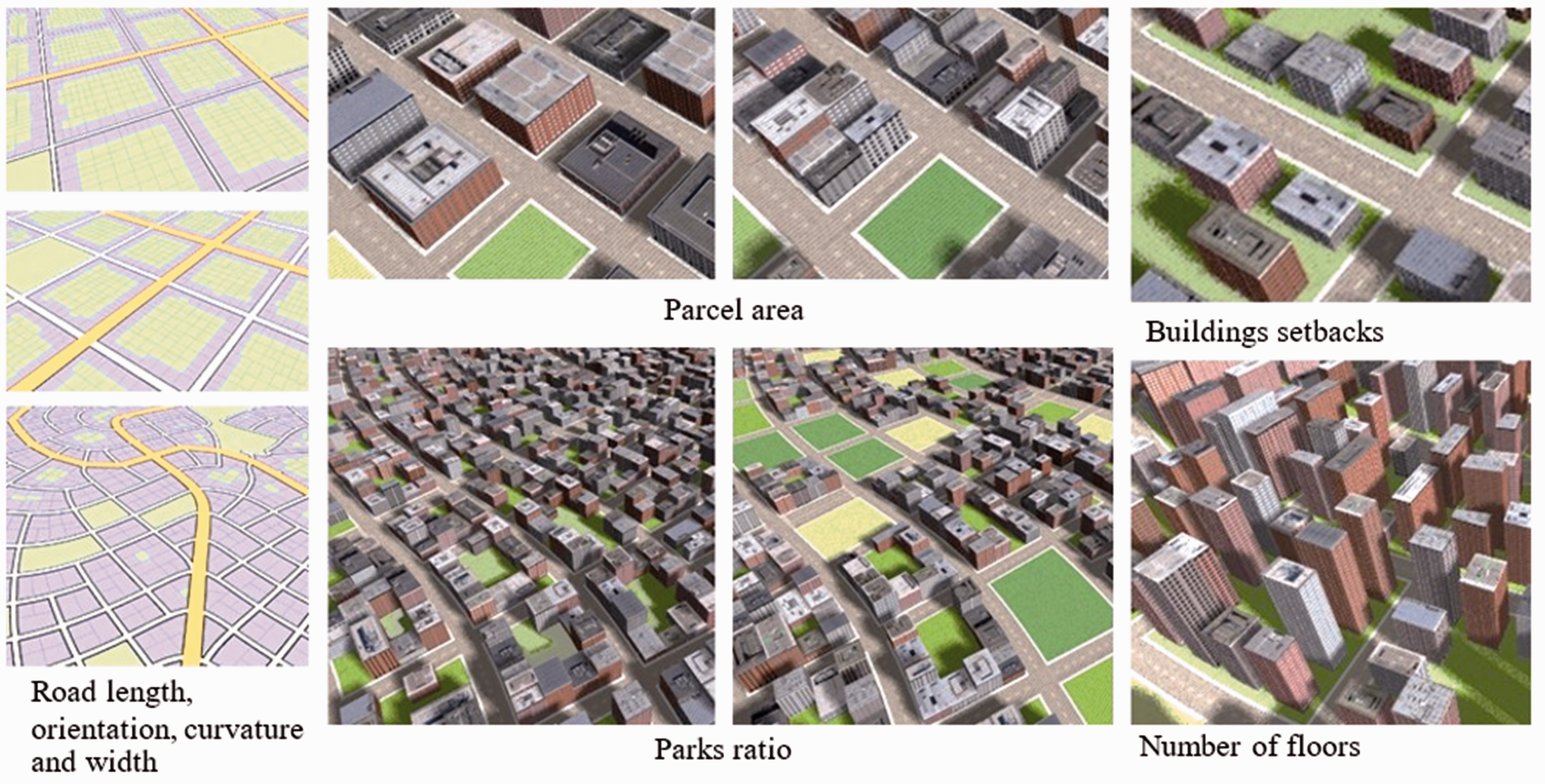
We represent an urban layout using a parameterized procedural model. While cities can occupy hundreds of square kilometers (e.g. a typical European city is 180 km2 in area (Eurostat, 2012)), we are only concerned with the part of a city near a river. Since the search space of all possible urban patterns is quite large, our procedural tool (1) divides the urban area into grid cells and provides design guidelines for each cell and (2) reduces complexity by generating urban layouts based on a few number of rules and parameters (i.e., 12 parameters). Our tool also enables users to import and export typical GIS data which facilitates migrating the tool’s outcomes into a wide range of GIS software.
Generation
Our procedural generation tool is inspired by Parish and Müller (2001), Vanegas et al. (2009) and CityEngine (from ESRI). Our tool first generates roads, then parcels, and finally buildings. Roads are divided into a two-level hierarchy (i.e., major and local roads). We adopt the tensor field approach (Chen et al., 2008) as it supports a wide variety of road network patterns using a single set of production rules. However, the original work by Chen et al. (2008) requires the user to specify the constraints by manually drawing the curves in order to generate the tensor field. To make the process fully automatic, we generate the constraints automatically from the parameters, and the tensor fields (Chen et al., 2008) are produced based on the generated constraints. Afterward, the tensor fields guide the generation of the road network. Once the road network is generated, we take each area surrounded by roads, called a block, and subdivide them into parcels, define parks, decide where to place buildings, and instantiate 3D building envelopes.
Parameters
Altogether, our procedural model is controlled by a 12-dimensional parameter vector
Urban procedural parameters.
average road length
road orientation
road curvature
major road width
minor roads width
Using
Parcels are defined based on a recursive subdivision of oriented bounding boxes (OBB) fit around each city block, as in Vanegas et al. (2012). Parcels are controlled by the following parameters:
average parcel area percentage of parcels selected as parks
Buildings are generated with the following parameters:
minimum number of floors maximum number of floors front
The building footprint is defined by calculating the offset from the parcel using the setback parameters
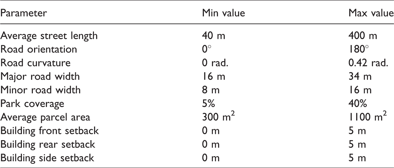
The variance of the input parameters representative of real-world locations are obtained with the assistance of our urban planning collaborators and by inspecting the cadastral data for 500 km2 of Wallonia (Belgium). Table 1 lists a summary of these findings.
Input parameters for the parameterized urban model engine.
Inverse engine
Our inverse modeling engine searches for an urban configuration similar to the initial layout but producing a lower flooding depth. To search through the solution space we make use of a controlled random walking optimization, an error function, and an NN-based acceleration.
Solution searching
Our inverse modeling engine provides a Graphical User Interface (GUI) that enables the user to interactively explore urban layout configurations that yield a desired water depth, Figure 4. The user interactively “paints” the desired water depth or uploads an image containing per cell values. As one option, we provide a mechanism to create such images with each cell encoded by 1 (low importance), 2 (median importance), or 3 (high importance). For example, the user may specify certain key areas to have relatively less water depth (e.g. residential areas) and other areas may have higher water depth (e.g. parks). Alternatively, the user could specify a desire to lower the average water depth of the entire area but at the price of not being able to control where the reduction is lowest. Our method also enables the user to control the tradeoff between similarity of the optimized urban model to the initial model and the amount of water depth reduction.
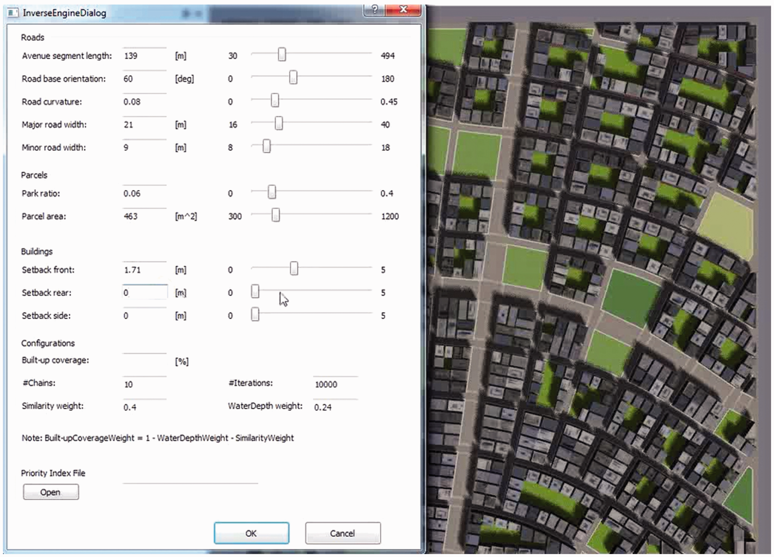
GUI of the inverse modeling engine.
MCMC-based optimization
The optimization consists of a Markov Chain Monte Carlo (MCMC) based search through the solution space. Our optimization uses
This optimization seeks
Error function
The optimization error function is a weighted sum of three objectives: maintaining a similar building coverage between the initial model and the optimized urban layout, achieving the desired water depth values in the optimized urban layout, and keeping the optimized parameter vector as similar as desired to the initial one. The use of building coverage is to ensure the new configuration can house the same number of people (note: we set number of floors at 4 so the gross floor area of all buildings is maintained in all test-cases presented in this paper); simply removing buildings will decrease flood level but of course leave no space for people.
The optimization error function G is the number of total outputs.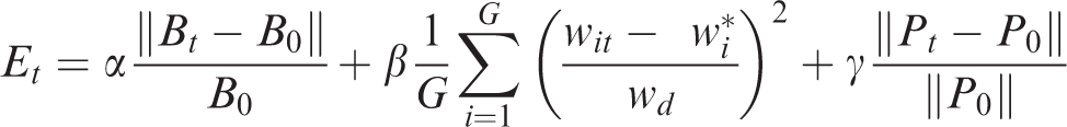
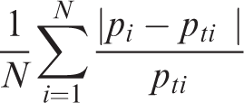
The layout similarity level is calculated as follows
Acceleration
To accelerate produce an interactive system, we make use of two trained neural networks (NNs). First, during each step of the optimization, a hydraulic simulation must be computed which can quickly lead to a very time consuming process. A typical hydraulic simulation run requires about two to three hours on a desktop PC. We accelerate performance significantly by using an NN. The hydraulic model is used to train the NN.
With the Caffe framework (Jia et al., 2014), we build a single-layer fully connected NN (including Dropout layer and ReLU Activation layer) and train it to predict a grid of water depth values
Results and discussion
We implement our system in C++, using Qt and OpenCV, and running on a desktop computer clocked at 3.20 GHz with an NVIDIA GTX780 graphics card and 24.0 GB RAM. This section shows several analysis and case-study results. Although some urban patterns might not be represented accurately, our urban generation system supports a wide variety of typical urban patterns, which enables us to effectively find a desired pattern from an otherwise huge search space (Figure 5).
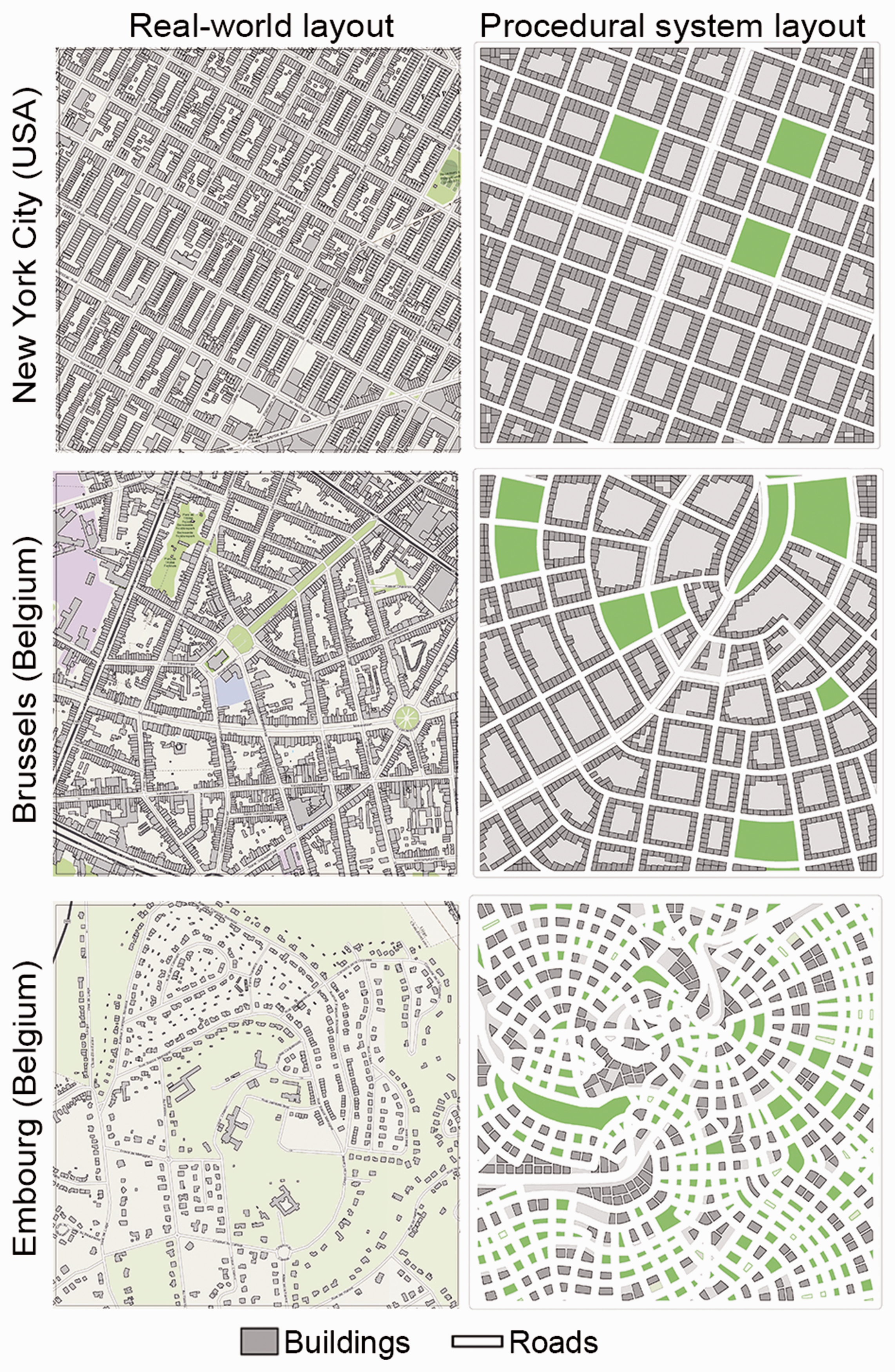
Real-world layouts versus procedural urban generator layouts.
Flooding simulation: Our porosity WOLF 2D model runs for an average of 2.5 hours to calculate the water for each urban layout versus about 10 days using the classical WOLF 2D model. The relative average water depths errors between the classical WOLF 2D and porosity WOLF 2D for three test cases is less than 1% (≈1 cm). However, the optimization process may last for several days to find the optimal urban layout using porosity WOLF 2D model – thus we train an NN.
Neural networks: We train a hydraulic-model NN and a building coverage NN. The hydraulic-model NN is trained using our dataset of 7000 precomputed flood depth solutions for a random set of urban configurations. After training, we compare the output of the NN to that produced by the porosity WOLF 2D model for two layouts (Figure 6). In this comparison, we use an NN trained to produce 20 × 20 water depth values, or 400 outputs. The comparison demonstrates that the average water depth of the trained NN closely resembles the ones produced by the porosity WOLF 2D model.
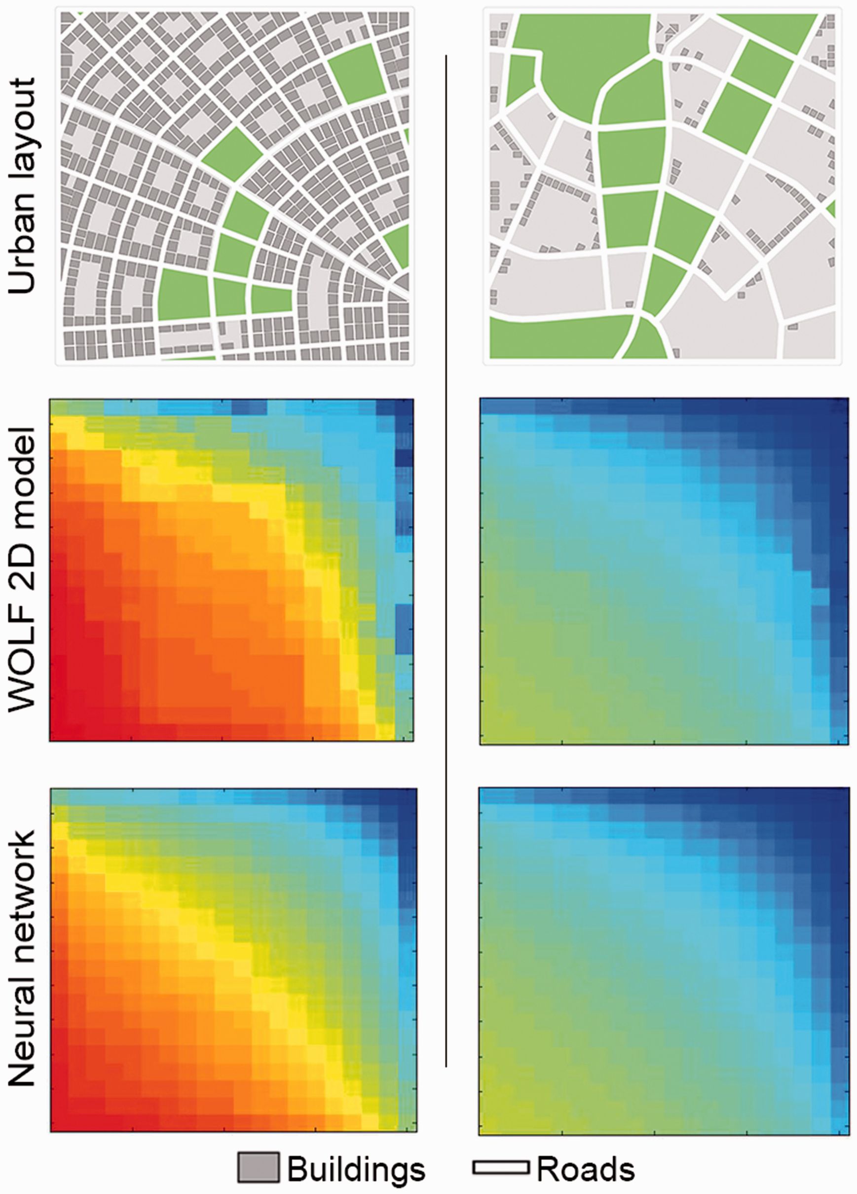
Water depth resulted maps from hydro model and NN for 400 outputs. Each cell represents average water depth for 50 m2 area.
We also compare the performance of our hydraulic-model NN to the use of a standard nearest neighbor linear interpolation (Figure 7). The multiple graphs show the number of test cases for different relative error rates (3%, 4%, and 5%) and for different output spatial resolutions – for example, 1 corresponds to obtaining a single depth value for the entire urban layout, 16 corresponds to obtaining 4 × 4 depth values, 100 corresponds to obtaining 10 × 10 depth values, and so forth. Overall, the NN performs much better than k-nearest neighbor (KNN) interpolation implying that the NN is able to “learn” the function well. We choose the 20 × 20 output resolution for most of our results because it yields a good balance between spatial resolution and accuracy.
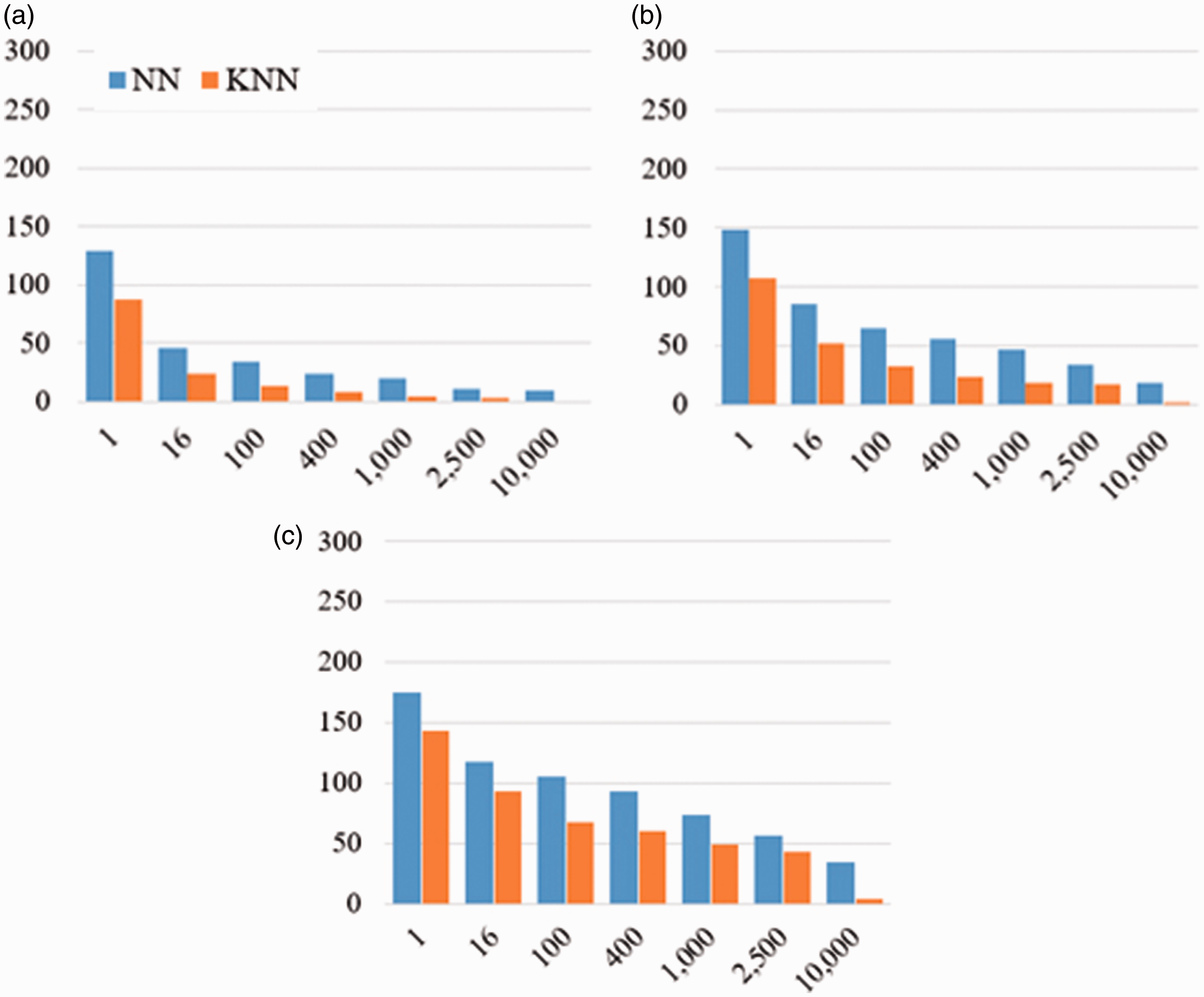
Water depth error plots for 300 test cases considering several outputs. X-axis represents number of output and Y-axis represents number of test cases. (a) corresponds to 3%, (b) corresponds to 4% and (c) corresponds to 5% relative error.
Figure 8 shows the error rate and validation of our building coverage NN. This NN is trained using 80,000 randomly sampled procedural models; overall the network yields very good results.
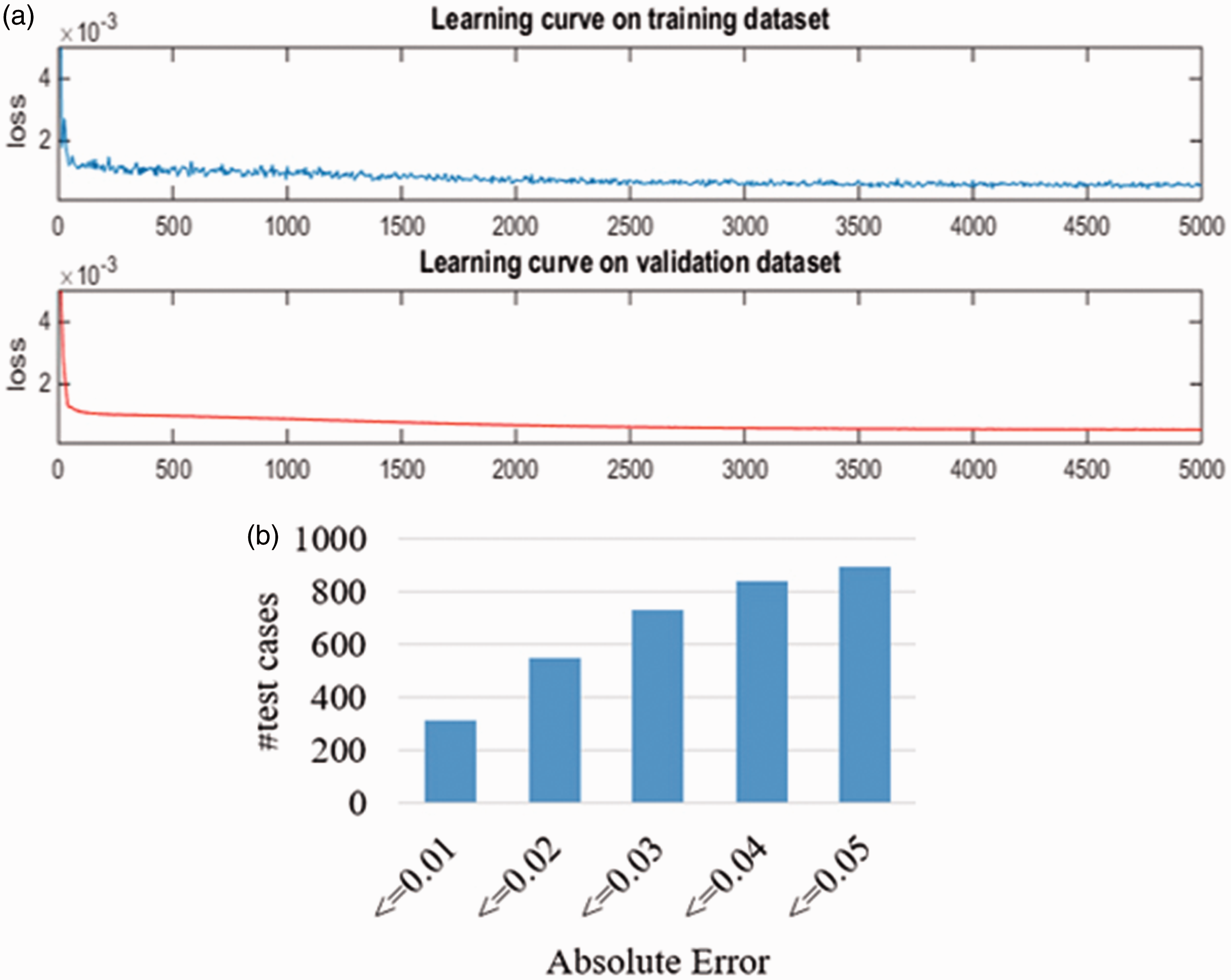
(a) learning curves presents loss (x-axis) versus iterations (y-axis) for training and validation datasets, and (b) the absolute error for a number of test cases (out of 1000) that occur between a range of absolute errors.
Urban layouts: In order to find the optimal layout that reduces water depth for an initial urban layout, we use our MCMC-based optimizer (Figure 4). The optimizer allows users to set initial parameter values and/or desired building coverage ratio. It also allows us to set the number of iterations, threads, and weights for similarity to the initial parameter values, reducing the average water depth, and building coverage weight. If the user does not explicitly provide a per-cell desired water depth, then with our GUI the user can define three levels of water-depth priority (i.e., low (L), medium (M), or high (H)) which can be defined for one or more target zones.
We tested our system on three different synthetic urban layouts. To set the initial parameter values (i.e., original layouts), we randomly selected scenarios from the urban generator. For all layouts, the system runs for about one minute to find the optimal layout that meets desired configurations (using a single core and without GPU acceleration). Our optimizer generates layouts that reduce the average water depth by up to 19%, 25% and 22% for cases 1, 2 and 3 respectively. Figure 9 shows original layouts and optimized layouts using a value for
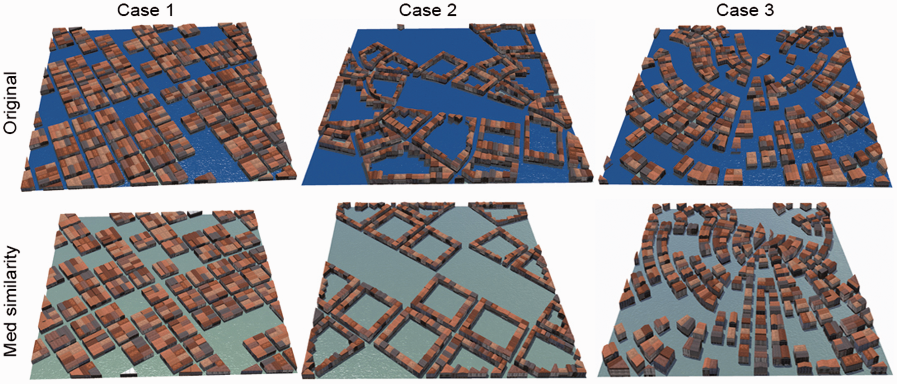
Three-dimensional simulations of the three test cases.
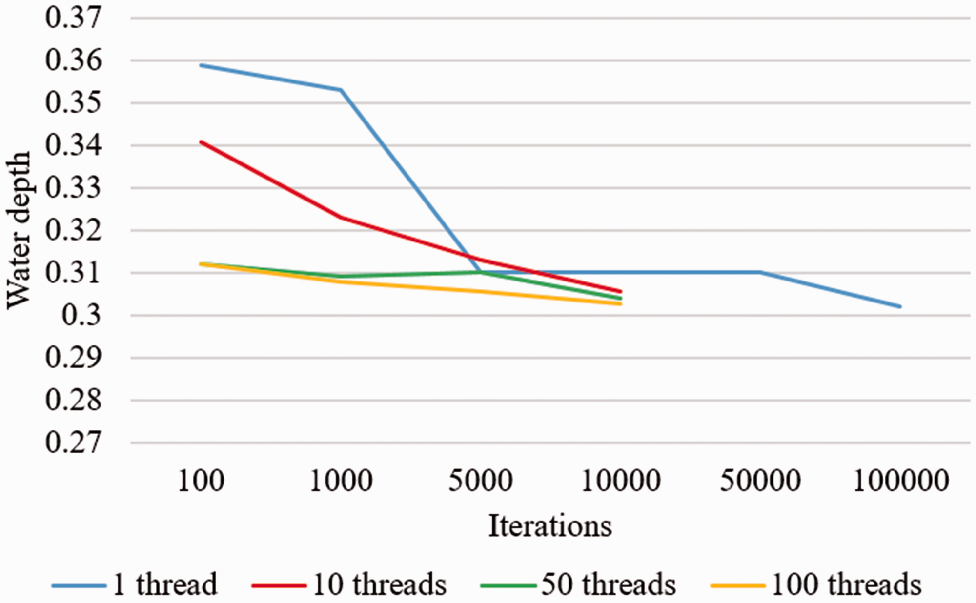
The convergence curve for case 3.
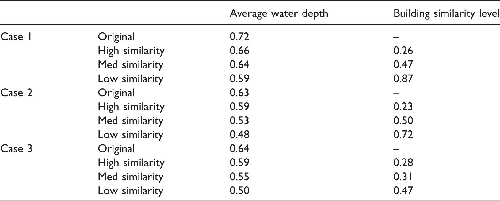
Figure 11 presents water depth reduction for different layout similarity levels. As expected, decreasing similarity will reduce water depth as the optimizer can search within a larger space of parameter combinations. It is also worth noting that case 2 shows the highest water reduction. Since this case has a relatively lower building coverage, the optimizer has more freedom to re-locate buildings so as to reduce flood levels.
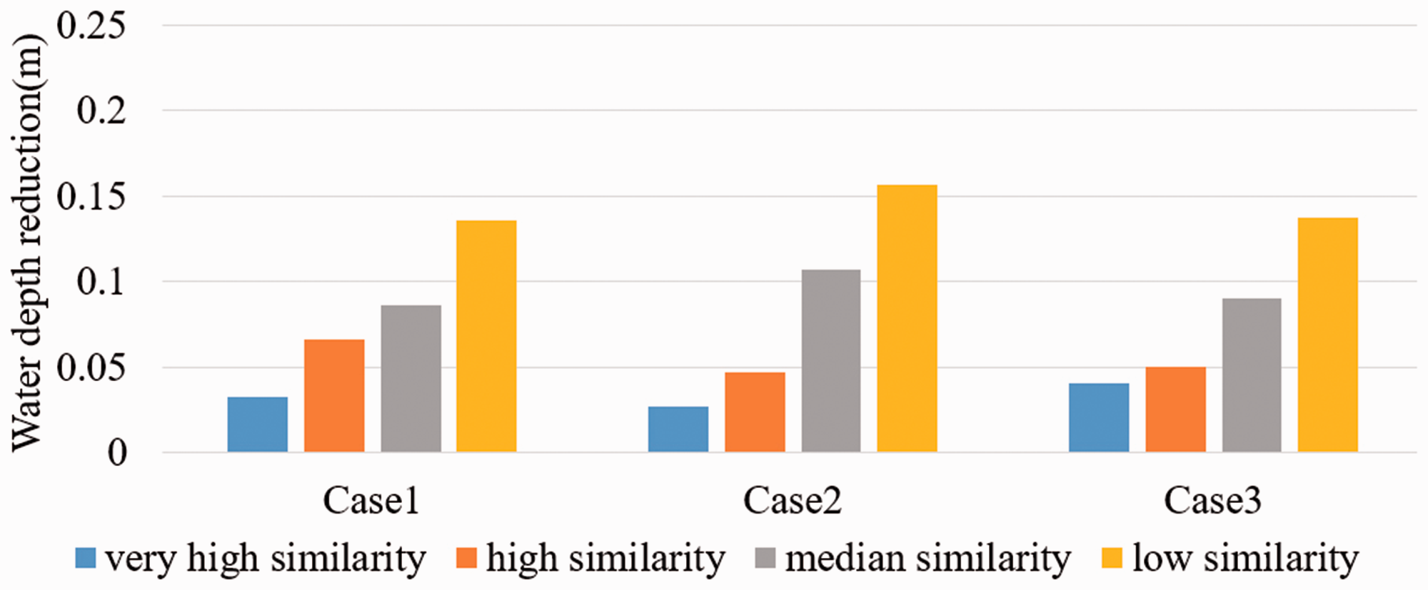
Water reduction (m) referenced to the original layouts.
For the same test cases, we set three priority (or importance) zones with regards to desired water level. Figure 12 gives all results for different zones. It is clear that the ability to reduce water depth for each zone depends on the test case. However, our system is still able to reduce water depth in a specific area. For instance, the water depth reductions for low similarity case within the high importance zone are 20%, 24% and 29% for cases 1, 2 and 3 respectively.
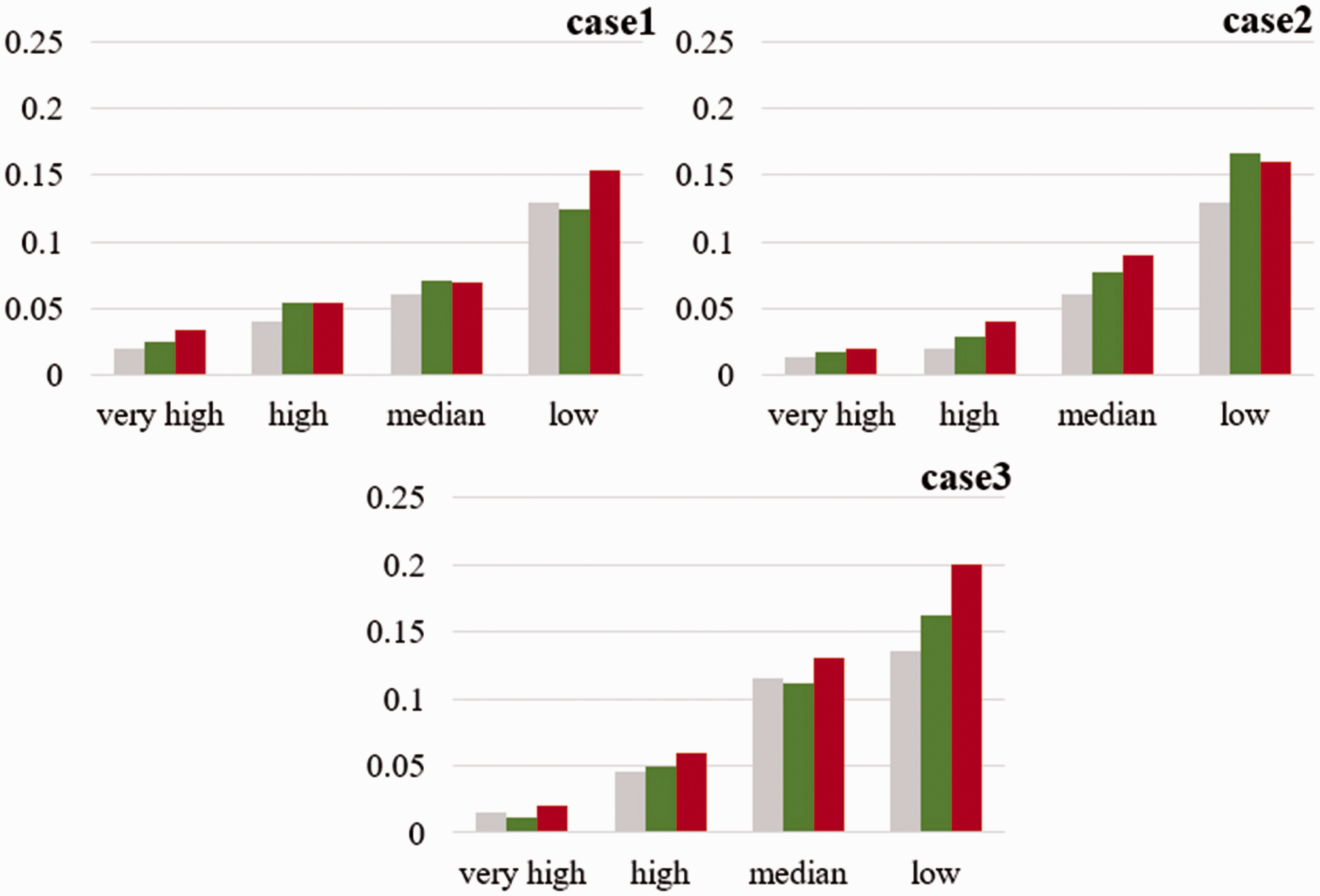
Water reduction in meters (x-axis) for various layout similarities (y-axis) considering different priority zones referenced to the original layouts.
Figure 13 contains the layouts used in Figures 11 and 12. Specifically, the top row shows the original synthetic urban layouts. The next nine scenarios correspond to the three different layout similarities for three test cases shown in Figure 9. The bottom row of scenarios in Figure 13 corresponds to the low-similarity solutions, each at three water depth priority levels, shown in Figure 12. The bottom two rows visually show the zones at the various selected priority levels.
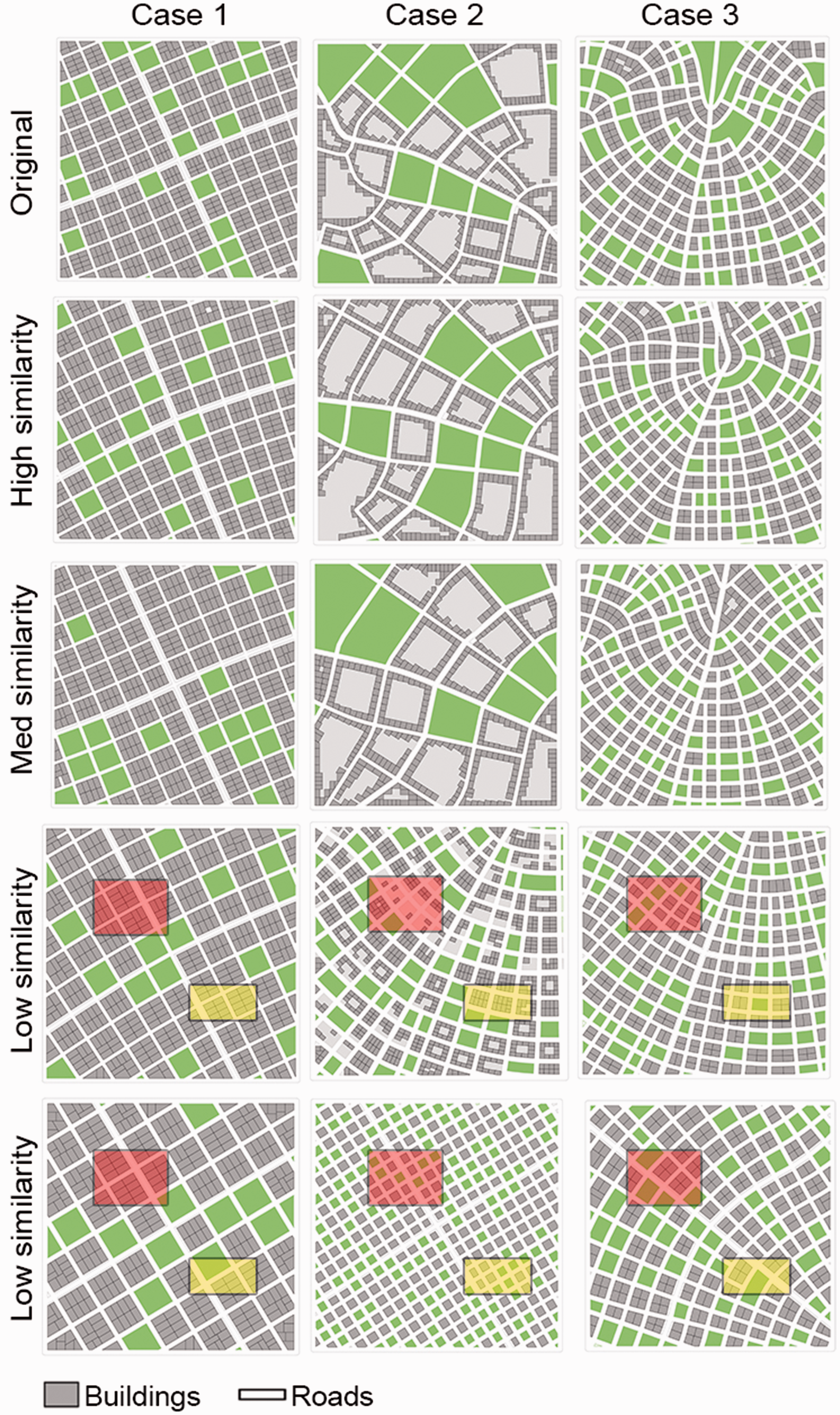
Resulted layouts from our system considering different similarity levels. It also shows low similarity layouts for importance zones, the bottom row, considering three zones: low importance (background), med importance (yellow zone) and high importance (red zone).
Table 2 lists the water depth and layout similarities for three test cases shown in Figures 9 to 13.
Average water depth for each case in Figures 9 and 13.
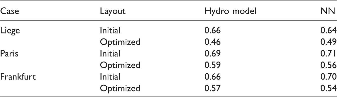
We test three real-world layouts located in Liege, Paris and Frankfurt. All three cities are subject to riverine floods. Figure 14 presents the real-world, initial and optimized layouts. Table 3 compares the average water depth for each case calculated by the porosity WOLF 2D model and our trained NN.
Real-world test cases.
Average water depth for the real-world case (Figure 14) calculated by the porosity WOLF 2D model and our NN.
Our system cannot automatically extract parameter values from existing layouts; therefore, we manually determine such parameter values to get layouts as close as possible to reality. Thereafter, the system automatically searches for the optimal layouts.
In general, our system keeps almost the same building coverage as in the original layout, and tends to increase parcel area and road width, and decreases road length and rear setback in order to achieve the optimal solutions. Road curvature and orientation do not play an important role. The optimal solutions always show larger parcel area; however, parcels can be subdivided into several buildings in the reality.
Conclusions and future work
We have coupled an automatic design approach for urban procedural modeling with a hydraulic model. Further, to achieve interactive feedback, our approach has employed NN and MCMC so that we get results in a few seconds. Based on several case studies, our findings highlighted that the impact of geometric characteristics of urban patterns (e.g. street width, park ratio, etc.) on flow properties during urban floods is significant. This is especially important for accurate flood/water simulations and for city planners concerned with flooding. Our approach can reduce water depth during the design phase of an urban layout and without other flood-mitigation costs.
There are some open problems remaining for future exploration. While our approach enables the user to design a flood-resistant urban area, the output controllability is limited. Recently, several interactive sketching frameworks for 3D modeling are proposed in computer graphics literature (e.g. Nishida et al., 2016, Guerin et al., 2017). Their approaches offer more controllability for the output 3D model by sketching. It would be interesting to add an interactive sketching interface to our framework. Another important next step in the research is the analysis of real-world case studies, which would showcase the operationality of the system and hence increase the impact of this assessment tool for urban planning practice. Specifically, the use of a deep learning network should be explored to directly take a real-world urban layout as input and produce estimated flood depth values. In addition, we would like to process larger geographic areas as well as consider other flooding scenarios (e.g. coastal floods, flash floods, etc.).
Footnotes
Declaration of conflicting interests
The author(s) declared no potential conflicts of interest with respect to the research, authorship, and/or publication of this article.
Funding
The author(s) disclosed receipt of the following financial support for the research, authorship, and/or publication of this article: The research was funded through the ARC grant for Concerted Research Actions for project number 13/17-01 financed by the French Community of Belgium (Wallonia-Brussels Federation) and through the European Regional Development Fund – FEDER (Wal-e-Cities Project).