
Abstract
Background:
The optimal position and number of anchors that need to be implanted in Hill-Sachs lesions (HSLs) during remplissage with Bankart repair (RMBR) to correct anterior glenohumeral instability remain unclear. Previous studies have mainly focused on anchor placement in the central, medial, and peripheral regions, as well as the superior and inferior poles of the HSL, but anchor placement in the upper or lower regions of the HSL has not been investigated.
Purpose:
To assess, using finite element analysis, the effect of placing 2 anchors in the superior or inferior regions of the HSL during RMBR on humeral head displacement and postoperative joint stability.
Study Design:
Controlled laboratory study
Methods:
Finite element models of the glenohumeral joint in the abduction external rotation position were created, including normal models and models with 2 anchors placed in the superior, inferior, or central regions of the HSL. Models with Bankart lesions and HSLs were established based on the normal glenohumeral joint model. Humeral head displacement was calculated by applying anterior dislocation forces and muscle contractions from the infraspinatus and teres minor muscles.
Results:
Models with 2 anchors placed in the superior (1.92 ± 0.00 mm) region of the HSL showed less anterior humeral head displacement than those with anchors in the lower (1.95 ± 0.00 mm) or central (1.95 ± 0.00 mm) regions under anterior dislocation load. However, posterior displacement was greater (2.05 ± 0.00 mm vs 1.90 ± 0.00 mm and 1.87 ± 0.00 mm) with anchors placed in the superior region under muscle contraction.
Conclusion:
The placement of 2 anchors in the upper portion of the HSL more effectively (P < .001) reduced anterior humeral head displacement than did the placement of anchors in the lower or central regions of the HSL. In clinical practice, external forces on the shoulder joint comparable with those causing dislocation may amplify this displacement difference, rendering it more prominent and clinically relevant. This provides a more refined reference for determining the position and number of anchors that need to be implanted into the HSL during RMBR surgery.
Clinical Relevance:
The placement of 2 anchors in the upper region of the HSL effectively reduces anterior displacement under simulated dislocation loads, while increasing posterior displacement under muscle contraction. This may enhance postoperative glenohumeral stability and reduce the risk of recurrent dislocations, offering valuable insights for clinical practice.
Recurrent anterior shoulder instability is the most common form of shoulder instability, typically resulting from trauma associated with bony defects.42,43 Bony defects were considered major contributors to the recurrence of shoulder instability.1,7 The prevalence of Bankart lesions and Hill-Sachs lesions (HSLs) in patients with recurrent anterior shoulder instability is estimated to range from 60% to 100%.45,55 Most Bankart lesions involve avulsion of the capsulolabral complex from the anteroinferior glenoid. Recurrent dislocations may lead to glenoid bone loss.4,35 A compression fracture caused by the anterior inferior glenoid rim impinging on the posterosuperior aspect of the humeral head is commonly referred to as an HSL. 25 Patients with recurrent anterior shoulder dislocations often have larger HSLs. 38
In 2008, Purchase and Wolf 44 introduced the “remplissage” technique, which involves arthroscopically filling the HSL with the posterior joint capsule and infraspinatus tendon. This technique is intended to address traumatic shoulder dislocations associated with both Bankart lesions and HSLs. Remplissage with Bankart repair (RMBR) is a relatively minimally invasive approach used to manage anterior glenohumeral instability. The goal is to convert intra-articular lesions into extra-articular lesions, thereby preventing engagement between the humeral head and the anterior edge of the glenoid cavity during glenohumeral abduction and external rotation. 8 Furthermore, the infraspinatus tendon is inserted into the bone defect of the humeral head, providing a checkrein effect that restrains anterior displacement of the humeral head. 59 The clinical outcomes of RMBR include a significant reduction in the recurrence rate of postoperative shoulder dislocation.31,34,36 Furthermore, no significant postoperative complications were observed.16,56
However, there is currently no standard for the optimal number and placement of anchors during RMBR, so differences in these parameters significantly influence surgical outcomes.13,17 With respect to the number of anchors, in some studies, researchers have implanted 2 anchors in the HSL.5,17,54 However, in other studies, researchers have implanted 1 to 3 anchors, depending on the size of the HSL.8,14,18 With respect to the location of anchor placement, in some studies, researchers have opted to implant anchors in the central region of the HSL.14,28 Moreover, in other studies, researchers have opted to implant anchors at the lateral periphery of the HSL.5,22,54 Additionally, in some studies, anchors were implanted at the superior and inferior poles of the HSL.20,39,42,44 In our clinical practice, a senior surgeon (Q.Z.) performed a double-pulley remplissage 40 in which two 3.4-mm absorbable suture anchors (Healix Transtend; DePuy-Mitek) were implanted in the upper portion of the HSL.
The application of finite element (FE) analysis (FEA) in orthopaedics to study the biomechanics and kinematics of bones, tendons, and ligaments is a well-established area of research.46,53 FEA is also widely used in shoulder research to investigate shoulder motion, fractures, and the performance of surgical implants.3,58 FE modeling offers a valuable alternative to the limitations of cadaveric and clinical studies by enabling the investigation of biomechanics and regenerative processes under controlled experimental conditions,6,17,57 while overcoming the challenges associated with the difficult acquisition of cadaveric specimens and the constraints imposed by ethical regulations.2,14,19,23 Previous FEA studies on the remplissage procedure have assessed the stability of the glenohumeral joint by assessing the displacement of the humeral head. 17 Currently, we are aware of no such FEA studies on the glenohumeral joint in the abduction and external rotation (ABER) position specifically investigating the remplissage procedure, which involves placing anchors in the superior or inferior portion of the HSL.
The objective of this study was to assess, through FEA, the effect of placing 2 anchors in the upper or lower region of the HSL on humeral head displacement within the glenohumeral joint.
Methods
FE Models of the Normal Glenohumeral Joint
The study was approved by the ethics review committee of Chinese People's Liberation Army General Hospital, and informed consent was obtained from all participants. Six participants were selected according to the following inclusion criteria: (1) <50 years of age, (2) no shoulder deformity, (3) no history of shoulder trauma, (4) no previous shoulder surgery, (5) no positive findings of disease on the basis of physical examination and functional assessment by an orthopaedic sports medicine specialist, and (6) no musculoskeletal abnormalities on computed tomography (CT) or magnetic resonance imaging (MRI). All participants in this study were male. The selection of 6 participants was not based on a specific rationale.
CT imaging data from the 6 participants (aged 23-40 years; height, 170-176 cm; weight, 62.5-80 kg) in the ABER position of the right shoulder joint were used for modeling. CT image data in DICOM (Digital Imaging and Communications in Medicine) format from all participants were imported into Mimics Research software (Version 21.0; Materialise) to generate glenohumeral joint bone models, including both the scapula and the humeral head.41,57 The initial skeletal models were imported into 3-matic Research software (Version 13.0; Materialise) for detailed analysis.24,27 The models underwent a series of refinements, including smoothing, repair, disturbance removal, and interference verification, before being face-meshed and body-meshed. This process produced six 3-dimensional (3D) FE models of the normal glenohumeral joint complex in the ABER position. A representative glenohumeral joint and its associated mesh are shown in Figure 1.

Normal glenohumeral joint model and its corresponding mesh. (A) The glenohumeral joint model in the abduction and external rotation position comprises the humeral head, scapula, supraspinatus, infraspinatus, teres minor, subscapularis, glenohumeral joint cartilage, joint capsule, and glenoid labrum. The simulations of other normal glenohumeral joint models in group 1 followed the same methodology, with no differences in the simulation approach. (B) Surface and volumetric mesh division of the typical normal glenohumeral joint model in group 1, with all other models in this group meshed in the same manner. The X, Y, Z axes in the figure are the default coordinate axes of the model and have no other special meanings.
The specifications of the models include the following: (1) Bone: the cortical bone thickness of both the humeral head and the glenoid was set at 3.2 mm. 30 (2) Cartilage: the mean thickness of the cartilage in the model was set to 1.3 mm on the basis of measurements from cadaveric specimens and MRIs, which indicated a range of approximately 1.0 to 1.5 mm.9,17,33 The reference population consisted of the general public, with cartilage thickness derived from a previous FEA of the glenohumeral joint. The contact friction coefficient between the cartilages was constant throughout the FEA, with the results indicating that variations in cartilage thickness had a negligible effect on the experimental outcomes. (3) Glenoid labrum: the glenoid labrum was modeled using the same nodes as those of the scapular and glenoid cartilages. 17 (4) Muscles: each muscle was modeled on the basis of the standard anatomic origins and insertions of the supraspinatus, infraspinatus, subscapularis, and teres minor, incorporating the footprint area at the humeral head.10,11 The material properties of each structure in the representative normal glenohumeral joint, as reported in the literature, are summarized in Table 1.17,57,58
Material Properties of Glenohumeral Joints

FE Models of the Bankart Lesion With HSL
The simulation of Bankart lesions with HSLs was based on 6 normal glenohumeral joint models. These Bankart lesions with HSLs were simulated by modifying the normal glenohumeral joint models. By referencing previous FE studies on the shoulder joint, a Bankart lesion with an extent of <25% was established. 26 Bankart lesion models with a lesion area accounting for 15% of the glenoid were established, with the lesions located at the 5- to 7-o'clock position of the glenoid (Figure 2A). No significant difference in glenoid bone loss was observed across the models. Off-track HSL models were constructed in the posterosuperior region of the humeral head. The HSL dimensions were 32 mm in length, 20 mm in width, and 3 mm in depth. The cortical bone was removed to simulate the damaged area and the humeral head cartilage was excised (Figure 2B). 17

Bankart lesion and Hill-Sachs lesion (HSL) of the glenohumeral joint. (A) The glenohumeral joint in the abduction and external rotation (ABER) position, showing a Bankart lesion. The purple dashed line marks the avulsion site of the anteroinferior glenoid labrum. (B) The glenohumeral joint in the ABER position with an HSL. The blue circle highlights the HSL, which was located at the posterosuperior aspect of the humeral head. The X, Y, Z axes in the figure are the default coordinate axes of the model and have no other special meanings.
FE Models of the Post-RMBR Glenohumeral Joint
Following the modeling of 6 glenohumeral joints with Bankart lesions and HSLs in the ABER position, SolidWorks software (Version 2021; Dassault Systèmes) was used to simulate the intraoperative placement of 3.0 mm–long anchors (Gryphon BR; DePuy-Mitek) in the Bankart lesion area, and 3.4-mm anchors (Healix Transtend; DePuy-Mitek) were implanted in the HSL.13,17,26
The positions of the anchors were varied to assess the effect of anchor placement at different locations on the HSL. Each of the 6 post-RMBR glenohumeral joint models were replicated 3 times, resulting in a total of 18 models. Anchors were implanted at different locations on the HSL in each of the 18 post-RMBR glenohumeral joint models. The models included were as follows: the post-RMBR glenohumeral model with anchors positioned in the upper region of the HSL, the post-RMBR glenohumeral model with anchors positioned in the lower region of the HSL, and the post-RMBR glenohumeral model with anchors located in the central region of the HSL. Combining 18 postoperative glenohumeral joint models and 6 normal glenohumeral joint models yields a total of 24 glenohumeral joint models for subsequent analysis. The 24 glenohumeral models were classified into 4 groups on the basis of anchor implant location. Group 1 included 6 normal glenohumeral models. Group 2 included 6 post-RMBR glenohumeral models with anchors implanted in the upper region of the HSL. Group 3 comprised 6 post-RMBR glenohumeral models with anchors implanted in the lower region of the HSL. Group 4 consisted of 6 post-RMBR glenohumeral models with anchors placed in the central region of the HSL (Figures 3 and 4).
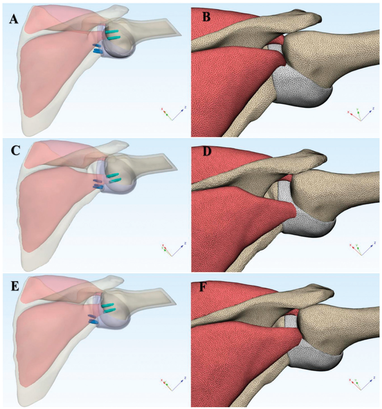
Post−remplissage with Bankart repair (RMBR) glenohumeral joint model and corresponding mesh. The 3 anchors highlighted in blue represent Bankart repair anchors. (A) Post-RMBR glenohumeral joint model with anchor insertion in the upper region of the Hill-Sachs lesion (HSL). (B) Surface and volumetric mesh of the post-RMBR glenohumeral joint model with anchor insertion in the upper region of the HSL. (C) Post-RMBR glenohumeral joint model with anchor insertion in the lower region of the HSL. (D) Surface and volumetric mesh of the post-RMBR glenohumeral joint model with anchor insertion in the lower region of the HSL. (E) Post-RMBR glenohumeral joint model with anchor placement at the center of the HSL. (F) Surface and volumetric mesh of the post-RMBR glenohumeral joint model with anchor placement at the center of the HSL. The X, Y, Z axes in the figure are the default coordinate axes of the model and have no other special meanings.

Anchor implantation positions in the post−remplissage with Bankart repair (RMBR) glenohumeral joint model. The red circles indicate the approximate margins of the Hill-Sachs lesion (HSL). Due to differences in observation angles, the 3 images exhibit certain discrepancies in appearance. (A) Finite element (FE) model of the humeral head with anchors implanted in the upper part of the HSL. (B) FE model of the humeral head with anchors implanted in the lower part of the HSL. (C) FE model of the humeral head with anchors implanted in the central part of the HSL.
FEA of 3D Glenohumeral Joint Models
The 3D models of the glenohumeral joint were discretized into tetrahedral meshes and imported into ANSYS Workbench (Version 19.2; ANSYS). The material properties of each structure of the glenohumeral model were assigned to enable static analysis 48 (Table 1). In this experiment, the boundary conditions for the scapula were set to Bond. The infraspinatus, supraspinatus, subscapularis, teres minor, glenoid labrum, joint capsule, and glenoid cartilage were bonded to the scapula. The medullary bone and cartilage of the humeral head were bonded to the cortical bone of the humeral head. The infraspinatus, supraspinatus, subscapularis, joint capsule, and teres minor muscles were attached to the humeral head. In previous in vitro experiments focused on the biomechanical analysis of the shoulder joint, a load of 10 N was applied. Similarly, in the present study, a 10 N load was applied to the glenohumeral joint to replicate the force environment on the infraspinatus and teres minor muscles, as well as the humeral head.50-52
First, after the material properties were edited and the boundary constraints were set, a 10-N load directed anteroinferior was applied to the humeral head models. This simulated the force environment during anterior dislocation of the glenohumeral joint in the ABER position. The total anterior displacement of the humeral head produced by both the normal glenohumeral model and the post-RMBR glenohumeral model was subsequently calculated. The total anterior displacement of the normal glenohumeral joint was compared with that of the post-RMBR glenohumeral joint. The differences in total anterior displacement of the glenohumeral joint when anchors were positioned at various locations within the HSL were subsequently analyzed.
Next, a 10-N load was applied in the direction of contraction of the infraspinatus and teres minor muscles, simulating the restriction of anterior humeral head displacement due to active contraction of these muscles in the ABER position of the glenohumeral joint.15,47 The total posterior displacement of the humeral head was calculated separately for each group of glenohumeral models. These results were then compared to analyze the differences in posterior displacement induced by anchor placement at various locations on the HSL during active contraction of the infraspinatus and teres minor muscles. The direction and magnitude of humeral head displacement from these FEA results were compared with those from previous studies to validate the established FE model and its corresponding findings.17,60
The following assumptions have been made: (1) Under biomechanical conditions simulating anterior dislocation of the glenohumeral joint, the data show a reduction in total anterior displacement of the humeral head when anchors were placed in the upper portion of the HSL compared with placement in the lower or central portions of the HSL. (2) Under biomechanical conditions simulating active contraction of the infraspinatus and teres minor muscles, the total posterior displacement of the humeral head was greater when anchors were placed in the upper portion of the HSL than when anchors were placed in the lower or central portions of the HSL.
Statistical Analysis
Data were analyzed using SPSS software (Version 25.0; IBM). Descriptive statistics, including the minimum, maximum, mean, and standard deviation, were computed. Discrepancies in total displacement across the following groups were assessed: group 1, group 2, group 3, and group 4. The differences observed were normally distributed, allowing for the use of multisample rank-sum tests. The Kruskal-Wallis H test was applied to examine the total displacement of the humeral head of the glenohumeral joint in each group under the 2 specified loading conditions. Normality of the data was assessed using the Shapiro-Wilk test. Statistical significance was evaluated via 2-tailed P values, with the significance level set at P < .05.
Results
Comparison of Total Humeral Head Displacement Under Anteroinferior Loading Conditions
A 10-N load was applied anteroinferior to the humeral head to replicate the biomechanical conditions associated with anterior dislocation of the glenohumeral joint. The total anterior displacement of the glenohumeral joint following RMBR in group 2 was significantly lower than that observed in the other groups in the ABER position (Figure 5). Displacement in group 2 ranged from 1.92 mm to 1.93 mm, with a mean displacement of 1.92 ± 0.00 mm; that in group 1 ranged from 2.02 mm to 2.03 mm, with a mean of 2.03 ± 0.00 mm; that in group 3 ranged from 1.94 mm to 1.95 mm, with a mean of 1.95 ± 0.00 mm; that in group 4 ranged from 1.95 mm to 1.95 mm, with a mean displacement of 1.95 ± 0.00 mm. The total displacement differed significantly among the 4 groups (P < .001).
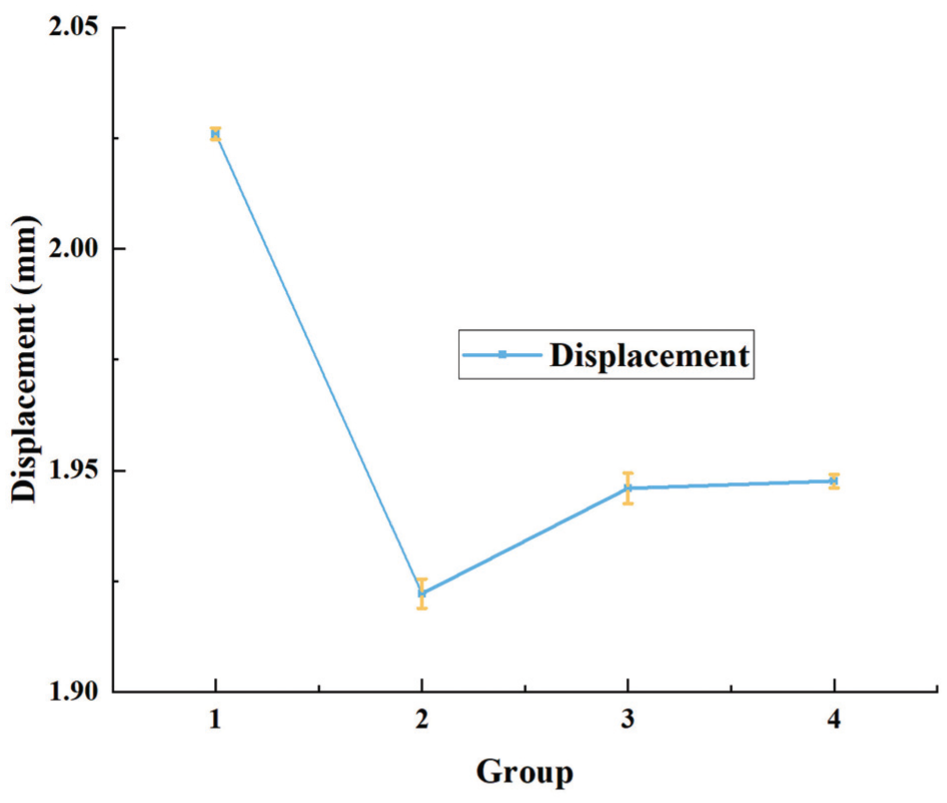
Comparison of total anterior displacement in the humeral head across groups under simulated anterior dislocation loading. Under simulated loading conditions of anterior dislocation, the humeral head in the post−remplissage with Bankart repair glenohumeral joint model of group 2 exhibited the lowest total anterior displacement, whereas the humeral head in the normal glenohumeral joint model of group 1 presented the greatest total anterior displacement.
Comparison of Total Humeral Head Displacement During Infraspinatus and Teres Minor Muscle Contraction
To simulate glenohumeral joint abduction, a 10-N load was applied to the infraspinatus and teres minor muscles. In group 2, the total posterior displacement of the post-RMBR glenohumeral joints in the ABER position was significantly greater than that in the other groups (Figure 6). The minimum displacement was 2.05 mm, the maximum displacement was 2.05 mm, and the mean displacement was 2.05 ± 0.00 mm. In contrast, group 1 exhibited a minimum displacement of 1.90 mm, a maximum displacement of 1.90 mm, and a mean displacement of 1.90 ± 0.00 mm (Table 2). Group 3 presented a minimum displacement of 1.89 mm, a maximum displacement of 1.90 mm, and a mean displacement of 1.90 ± 0.00 mm. Group 4 displayed a minimum displacement of 1.86 mm, a maximum displacement of 1.89 mm, and a mean displacement of 1.87 ± 0.00 mm. The total displacement differences among the 4 groups were statistically significant (P < .001). The observed differences can be attributed to the intrinsic differences in shoulder anatomy among the original participants.

Comparison of total posterior displacement of the humeral head across groups under simulated loading from active infraspinatus and teres minor muscle contraction. Under simulated loading conditions of active infraspinatus and teres minor muscle contraction, the humeral head in the post−remplissage with Bankart repair (RMBR) glenohumeral joint model of group 2 exhibited the greatest total posterior displacement, whereas the humeral head in the post-RMBR glenohumeral joint model of group 4 presented the smallest total posterior displacement.
Total Displacement of the Humeral Head in the ABER Position a
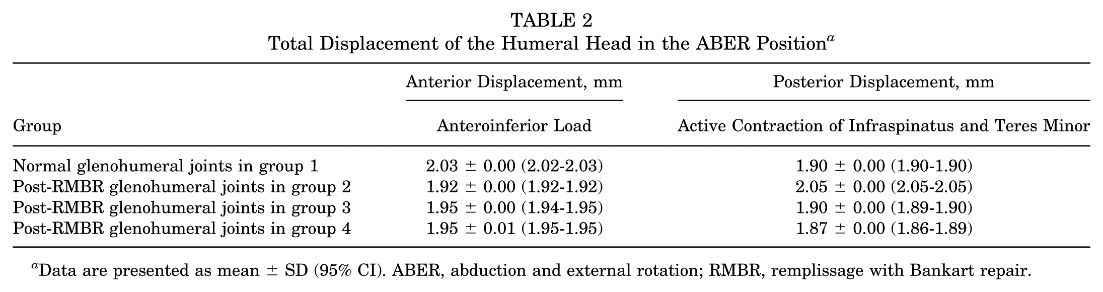
Data are presented as mean ± SD (95% CI). ABER, abduction and external rotation; RMBR, remplissage with Bankart repair.
Discussion
The most significant finding of this study was the validation through FEA that RMBR surgery with anchors placed in the upper region of the HSL site resulted in the greatest improvement in glenohumeral stability after RMBR in comparison with anchors placed centrally and in the lower portion. In the simulation of anterior glenohumeral dislocations, the total anterior displacement of the glenohumeral joints following RMBR with anchors implanted in the upper region of the HSL was less than that observed in the glenohumeral joints of the other groups. Furthermore, in response to loads that simulate active contraction of the infraspinatus and teres minor muscles, the post-RMBR glenohumeral joints in group 2 exhibited greater posterior displacement of the humeral head than the glenohumeral joints in the other groups did. In clinical practice, if the shoulder joint experiences an external force with a magnitude analogous to that triggering dislocation, this discrepancy in displacement is likely to become more prominent and clinically meaningful.
In instances of recurrent traumatic shoulder instability, an increased propensity for glenohumeral dislocation was observed when the joint was in a functionally significant degree of abduction. Furthermore, the joint was particularly susceptible to anterior dislocation when positioned in ABER.37,52 Consequently, the CT image data of participants in the ABER position were employed for FEA in our experiments. HSLs were frequently observed in cases of traumatic recurrent shoulder dislocation. In these instances, RMBR surgeries were typically performed in <25% of the cases where Bankart lesions coexisted with off-track HSLs. 12 The objective of the procedure was to prevent the HSL from re-engaging with the anterior lower part of the glenoid. 7
In the normal glenohumeral joint, the infraspinatus and teres minor tendons were crucial components of the posterior rotator cuff, facilitating compression, external rotation, and abduction of the glenohumeral joint. Furthermore, they contributed to the prevention of superior and anterior displacement of the humeral head by exerting posteroinferior forces, thus maintaining joint stability.15,47 Accordingly, an active contraction force was applied to the infraspinatus and teres minor muscles over the course of this experiment. The RMBR procedure results in alterations to the original anatomy of the glenohumeral joint, consequently affecting the biomechanical environment of the joint. 42 The most recent finding suggests that the checkrein effect and active muscle control resulting from the medial shift of the infraspinatus tendon insertion following RMBR contribute to the stability of the procedure. 60 Furthermore, the number and placement location of the anchors during RMBR may be significant determinants of the efficacy of surgical treatment. 17 Importantly, the location and number of anchors placed in the HSL during RMBR surgery have varied across previous studies.
Compared with the glenohumeral joints of the other groups, the results of the FEA indicate that the implantation of anchors in the upper portion of the HSL resulted in less anterior displacement of the humeral head when subjected to anterior dislocation forces and more posterior displacement of the humeral head when subjected to active contraction of the infraspinatus muscle. As a result, the anterior displacement of the humeral head was more limited. A cadaveric study revealed that after RMBR surgery, the humeral head displaced more posteriorly and inferiorly when the shoulder was abducted. 2 In a prior in vivo study using 3D MRI, compared with individuals with normal shoulder joints, patients who underwent the RMBR procedure exhibited more posteroinferior positioning of the humeral head in the ABER position during muscle relaxation. Furthermore, the humeral head shifted further posteriorly upon muscle contraction. 59 The experimental results of this study were compared with previous FEA and in vivo findings. The results were consistent with earlier data, and the observed increase in values does not affect the overall conclusions of the study.17,59 Although the model excluded other structures, such as the glenohumeral ligaments, the FEA produced results consistent with those of previous in vivo studies. No significant differences in infraspinatus strength were observed when comparing postoperative glenohumeral joints, which were assessed ≥24 months after surgery, with normal joints.36,42 Additionally, MRI scans confirmed successful healing of the infraspinatus tendon at the HSL site. 60 These findings suggest that infraspinatus strength can be restored to normal levels following the RMBR procedure. Additionally, the same force magnitude can be applied in FEA. This does not affect the comparison of humeral head displacement between the normal glenohumeral joint and the post-RMBR glenohumeral joint under the same infraspinatus muscle force.
The RMBR procedure enhances glenohumeral joint stiffness, contributing to joint stability. However, the associated increase in stiffness and motion limitations due to the capsulodesis effect should be considered.14,49 The RMBR procedure modifies the kinematics of the glenohumeral joint. Similarly, other nonanatomical surgical techniques designed to improve shoulder stability have shown similar results, ultimately contributing to the development of osteoarthritis.2,32 Previous research has revealed a strong association between glenohumeral instability repair and the later development of glenohumeral arthritis.39,49 The Putti-Platt procedure, like the RMBR procedure, restricts anterior displacement of the humeral head and is linked to a significant increase in both the incidence and the severity of postoperative osteoarthritis. Consequently, the potential long-term risk of osteoarthritis following RMBR surgery warrants attention.29,60 Furthermore, static posterior subluxation of the humeral head is often associated with glenohumeral arthritis. 21 As the RMBR procedure enhances posterior displacement, it may predispose patients to the subsequent development of osteoarthritis.
Limitations
It is essential to acknowledge the limitations of this study. The experiment did not incorporate various numbers of anchors; however, the number of anchors may influence postoperative outcomes. In the FEA, it was assumed that the anchors remained stable after implantation, without considering potential loosening due to factors such as osteoporosis or the risk of retearing associated with suboptimal rotator cuff tissue quality. These complications should be evaluated on a patient-specific basis. The sample was restricted to male participants, without accounting for variables such as age, sex, or individual differences in skeletal and soft tissue anatomy. To increase the generalizability and robustness of future studies, incorporating imaging data from a more diverse cohort would be advantageous. The post-RMBR model was developed on the basis of a healthy glenohumeral joint model, but obtaining imaging data from a healthy shoulder in post-RMBR patients presents considerable challenges. Future research could benefit from the use of imaging data from both the preoperative healthy state and the postoperative condition of the same patient for FEA. Certain anatomic components, such as shoulder muscles, glenohumeral ligaments, and long head of the biceps tendon, were excluded from the shoulder joint models. The omission of these structures from the shoulder joint complex model could have resulted in an overestimation of humeral head displacement in the FEA simulations relative to actual clinical observations. This does not influence the comparison of humeral head displacement between the normal and post-RMBR glenohumeral joints following RMBR surgery. Future studies should employ more refined models that more precisely replicate the relevant anatomic structures. The establishment of Bankart injury models at the 5- to 7-o'clock position of the glenoid was based on previous FEA studies. Specifically, in that previous research, Bankart lesions were set within the 2- to 7-o'clock position of the glenoid. 26 To fulfill the criterion of a Bankart lesion size <25%, we opted to establish lesions accounting for approximately 15% of the glenoid surface, with their location defined as the 5- to 7-o'clock position of the glenoid. However, the placement of the Bankart lesion may exert an influence on the selection of anchor positions in the HSL region, which could potentially affect the experimental results.
Conclusion
The implantation of 2 anchors in the upper region of the HSL during the RMBR procedure resulted in minimal anterior displacement of the humeral head under simulated anterior dislocation loads compared with anchor placement in the lower or central regions of the HSL. Additionally, the greatest posterior displacement of the humeral head was observed when the infraspinatus and teres minor muscles were simulated to contract actively. In clinical practice, when the shoulder joint is subjected to an external force whose magnitude is comparable with that inducing dislocation, such a displacement difference may become more pronounced and clinically relevant. These findings suggest that anchor placement in the upper region of the HSL may provide superior postoperative glenohumeral joint stability compared with placement in the lower or central regions.
Footnotes
Final revision submitted September 3, 2025; accepted October 6, 2025.
One or more of the authors has declared the following potential conflict of interest or source of funding: This study was supported by Capital's Funds for Health Improvement and Research (2022-2-5051) and Chinese People's Liberation Army General Hospital Transformation Project (ZH19008). AOSSM checks author disclosures against the Open Payments Database (OPD). AOSSM has not conducted an independent investigation on the OPD and disclaims any liability or responsibility relating thereto.
Ethical approval for this study was obtained from Chinese People's Liberation Army General Hospital (S2023-026-01).