
Abstract
Background:
Because a valgus deformity is frequently associated with patellar instability, medial closed wedge distal femoral osteotomy (MCWDFO) has gained popularity. While the influence of MCWDFO on the leg axis in the coronal plane is widely understood, information is relatively scarce on possible concurrent effects on the posterior distal femur angle (PDFA) and femoral torsion (FT) caused by different hinge axes.
Hypothesis:
The authors hypothesized that a neutral hinge axis changes only the alignment in the frontal plane and that rotation of the hinge axis significantly changes sagittal and axial anatomic parameters.
Study Design:
Descriptive laboratory study.
Methods:
The study used a 3-dimensional surgical simulation to perform MCWDFO with a stepwise increase in varization by 1° (0°-15°). Surface models were created from computed tomography scans of 12 cases of femoral valgus deformity and 23 physiologically aligned lower limbs, resulting in 6370 simulations. Anatomic landmarks were determined for each simulation to measure the hip-knee-ankle angle, mechanical lateral distal femoral angle, PDFA, and FT. Axial and sagittal rotations of the hinge axis were tested for their effects on the PDFA and FT.
Results:
Axial rotation of the hinge axis significantly affected the PDFA, with changes of 1.9°± 0.1° (mean ± SD) per 10° of rotation at a hinge closure angle of 10° (P < .001). Anterosuperiorly inclined sagittal hinge rotation was highly negatively correlated to FT changes (–0.82; P < .001). For the neutral hinge axis, only minimal nonsignificant changes were observed in the PDFA (P = .85) and FT (P = .98).
Conclusion:
With this 3-dimensional simulation study, a definition for a hinge axis in the MCWDFO could be found in which only coronal changes occur. By rotating the hinge axis in the axial plane, the PDFA can be significantly influenced; conversely, the FT can be changed by rotation in the sagittal plane.
Clinical Relevance:
Understanding the effect of hinge axis orientation in MCWDFO is crucial for enhancing surgical accuracy, thereby improving patient outcomes in treatments involving knee deformities and avoiding unintended changes.
Alignment of the lower limb plays a crucial role in the development of cartilage damage as well as instability in the knee.1,18 Valgus deformities can originate in the femur and the tibia, whereas femoral deformity is frequently due to hypoplasia of the lateral femoral condyle.7,11,17,33 Because valgus deformity is frequently associated with patellar instability, medial closed wedge distal femoral osteotomy (MCWDFO) has gained popularity as a promising procedure to correct valgus malalignment and patellar instability.4,12,13,34 Despite changes in the coronal plane, MCWDFO leads to additional anatomic changes (eg, in the patellofemoral joint).10,37
However, 3-dimensional (3D) anatomic changes introduced by MCWDFO remain relatively unknown, in contrast to changes in the more intensively investigated high tibial osteotomy (HTO).27,28,35 It was shown that posterior tibial slope can be influenced by axial hinge axis rotation. 35 While the influence of MCWDFO on the leg axis in the coronal plane is widely understood, information is relatively scarce on possible concurrent effects on the posterior distal femur angle (PDFA) and femoral torsion (FT) caused by different hinge axes. 10
Computer-assisted modeling and simulation of surgical procedures through 3D anatomic models enable various osteotomy techniques and their influence on different alignment parameters to be investigated without exposing patients to invasive procedures or multiple radiographic investigations.15,22
The study aimed to identify a neutral hinge axis that alters alignment exclusively in the frontal plane during MCWDFO. Additionally, it sought to quantify the effects of sagittal and axial hinge axis rotation on PDFA and FT. The hypothesis proposed the existence of a neutral hinge axis that restricts alignment changes to the frontal plane, while asserting that hinge axis rotation significantly influences sagittal and axial alignment parameters.
Methods
Case Selection
This simulation study was institutional review board approved (EC-Nr 17-044). Combined hip, knee, and ankle (HKA) computer tomography (CT) scans were acquired from anonymized patients treated for femoral valgus deformity between 2017 and 2023 (n = 12; valgus group), as were postmortem whole body CT scans (neutral group). The inclusion criterion of the valgus group was a valgus deformity >5° (HKA angle >185°). In the neutral group, among 1205 postmortem CT scans available, 23 patients of White European descent presenting physiologic alignment were included, and 1182 were excluded owing to the exclusion criteria applied to both groups: knee fracture, severe bone defects, knee prostheses, and age <18 or >50 years. For the neutral group, cases were additionally excluded for pathologic values in HKA angle, mechanical lateral distal femur angle (mLDFA), PDFA, and FT.
3D Models and Anatomic Landmarks
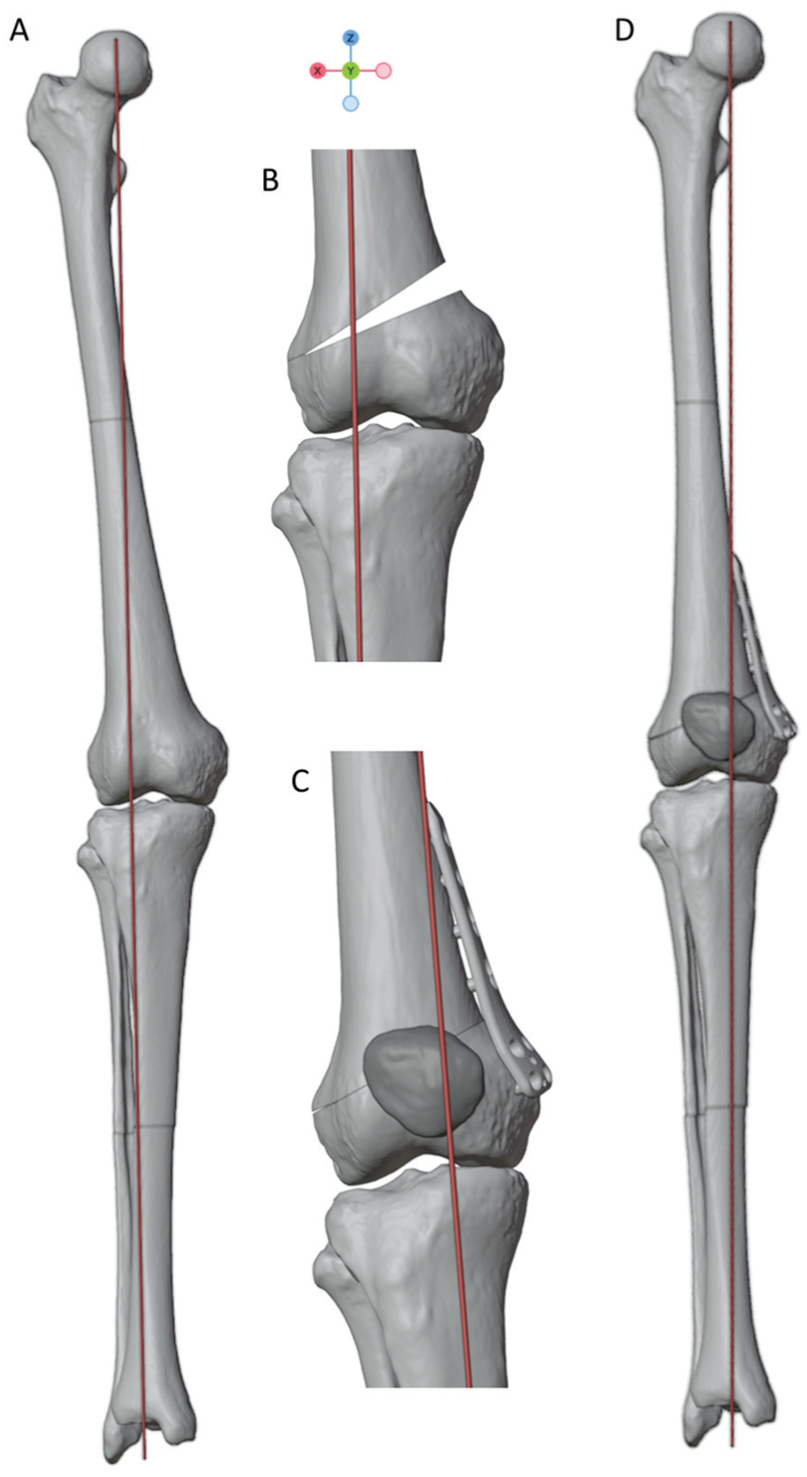
Lower extremity CT scan was performed in all cases in a supine position with a maximum slice thickness of 1 mm. A 3D bone model was reconstructed from CT data via Slicer (Version 3.5.0; https://www.slicer.org). 8 The coordinate system and anatomic landmarks for calculation of HKA angle, mLDFA, PDFA, and FT (Figure 1) of the lower limb were set by an experienced orthopaedic surgeon in Blender (Version 3.5.1; Blender Foundation) as previously described.14,15 The defined landmarks have demonstrated high intra- and interobserver variability.14,15 For the coordinate system, a best-fitting cylinder of both femoral condyles defined the x-axis as a mediolateral axis. The z-axis was defined by a line orthogonal to the x-axis passing through the femoral head center as commonly performed.9,23 Per definition, the y-axis is orthogonal to the x- and z-axes and oriented anteroposteriorly. The resulting model enabled accurate 3D representation of the anatomy and geometry of the femur and tibia as a precondition for virtual MCWDFO surgery.

Definition of PDFA measurement in 3 dimensions. (A, B) The femoral joint line is defined as an anteroposterior line connecting the proximal trochlea groove (TGPP) with a point (FCPCP) between the posterocranial femur condyles (FMCPC, FLCPC). 30 (C) The PDFA is defined as the angle between the femoral joint line (defined as the TGPP and FCPCP) and the mechanical femur axis. (D) Coronal plane: mechanical lateral distal femur angle (mLDFA) was defined as the lateral angle between the femoral mechanical axis and the joint line of the distal femur condyles. FCPCP, point where a line between the FMCPC and FLCPC is intersected by a sagittal plane through the TGPP; FLCPC, posterocranial point of the lateral femur condyle; FMCPC, posterocranial point of the medial femur condyle; PDFA, posterior distal femur angle; TGPP, trochlea groove proximal point.
Virtual 3D Surgery of MCWDFO and Standard Hinge Axis
A standard MCWDFO was performed virtually per the following method. The standardized hinge point was calculated by predefined landmarks of the lateral tibia plateau (TLCL; most lateral and cranial point on the lateral tibia plateau) as well as the lateral posterior femur condyle (FLCP; most posterior point on the lateral femur condyle) (Figure 2). 15 To do so, the craniocaudal distance from the FLCP to the TLCL was calculated. The hinge point was positioned 1.5 times the craniocaudal distance in the cranial direction from the TLCL and located in the lateral metaphysis of the femur. Its placement was individually verified through visual inspection.

The hinge point is located in the lateral metaphysis of the femur. It is defined cranial to the most lateral point on the tibial plateau (TLCL). The distance between the hinge point and TLCL is defined as 1.5 times the craniocaudal distance between the TLCL and a point most posterior of the lateral femur condyle (FLCP). Six sagittal axes (A) (+, anterosuperiorly inclined; –, anteroinferiorly inclined) and 6 axial hinge axes (B) (+, anteromedial inclined; –, anterolateral inclined) were determined by rotating the neutral hinge axis at the hinge point. The standard hinge axis (0°) was defined as parallel to the femoral joint line (red line) in the anteroposterior direction passing through the hinge point (red point).
The hinge axis was oriented parallel to the anteroposterior femoral joint line (red line) in the sagittal view, as shown in Figure 2. 30 The hinge is planned at the upper border of the lateral femoral condyle to avoid unstable hinge fractures. 24
Thirteen hinge axes were established: 1 neutral hinge axis, 6 hinge axes with different orientations in the axial plane (referred to as axial hinge axis), and 6 hinge axes with different orientations in the sagittal plane (referred to as sagittal hinge axis). The neutral hinge axis was characterized as having a rotation of 0°, passing through the hinge point, while being parallel to the sagittal femoral joint line and thereby orthogonal to a line passing through points of the most posterior femoral condyles in the axial plane (Figure 1). Additionally, 6 axial hinge axes (±10°, ±20°, and ±30°) were generated by rotating the neutral hinge axis in the axial view (as depicted in Figure 2). A positive value for an axial hinge axis indicated that the hinge was located anterolaterally on the axial plane, while a negative value indicated a posterolateral location. Similarly, 6 sagittal hinge axes (–10°, –20°, and −30°) were created by modifying the angle of the standard hinge axis in the sagittal plane (as illustrated in Figure 2). A positive value for a sagittal hinge axis represented an anterosuperiorly inclined orientation in the sagittal plane, while a negative value indicated an anteroinferiorly inclined orientation in the sagittal plane.
The osteotomies were simulated with a stepwise increment of 1° of varization from 1° to 15° for each hinge axis, resulting in 6370 simulations (Figure 3). Additionally, a correction to 1° varus alignment was targeted in the valgus group.3,20,26
(A) Three-dimensional bone model with femoral valgus deformity. Three-dimensional planning of (B) medial closed wedge distal femoral osteotomy and (C, D) final result with realignment of the lower limb.
Outcome Measurements
The following outcomes were measured by the anatomic landmarks via a Python script in Blender pre- and postsimulation: PDFA, LDFA, HKA angle, and closing wedge angle.14,15 The PDFA was defined as the angle between the femoral joint line and the femoral axis in the sagittal plane, as shown in Figure 1. FT was measured according to Goutallier in the axial view as the angle between a line through the femoral neck and a line at the posterior femoral condyles. 16 For each simulation, the PDFA, HKA angle, and FT were measured in the 3D bone models. To compare the influence of different hinge axes, outcome measurements were compared following 10° of varus correction.
Statistical Analysis
All data were expressed as mean and standard deviation. The sample size was calculated by G*Power (Version 3.1.9.6) based on changes of the posterior slope in HTO in previous studies.25,35 A minimum sample size of 27 was required to achieve a power of 80% (effect size, 0.5; α = 0.05).
Distribution was assessed with the Shapiro-Wilk test. After nonnormal distribution was conformed, the differences between groups were determined by the Kruskal-Wallis test. Post hoc testing via a pairwise Wilcoxon test was used to assess the differences between the groups. Pearson correlation coefficients (r) were used to assess the extent to which 2 variables are related: 0.1 < r < 0.3, weak correlation; 0.3 < r < 0.7, moderate correlation; and 0.7 < r < 1.0, strong correlation. Multiple linear regression was performed to identify independent factors influencing outcome after MCWDFO. The significance level was set at .05. The analysis was performed in R Studio (Version 2023.03.1; Posit Software, PBC).
Results
Postoperative Outcome in Standard Hinge Group
Twelve cases of symptomatic femoral valgus deformity and 23 cases of neutrally aligned postmortem-acquired CT scans were anonymously included in this study. There were no significant differences regarding PDFA and FT between the neutral group and the valgus group before virtual osteotomy, while the mLDFA and HKA angle differed significantly (Table 1).
Presimulation Values of the Valgus and Neutral Alignment Group a

Data are presented as degrees. HKA, hip-knee-ankle; mLDFA, mechanical lateral distal femur angle; PDFA, posterior distal femur angle.
The mean correction angle for the valgus group was 7.1°± 3.4° (range, 2°-14.8°) to achieve the target HKA angle of 1° varus alignment.
Neutral Hinge
Following 10° varization in the neutral hinge, no changes of FT and minimal changes of PDFA were observed as compared with presimulation values (Table 2). This effect was detectable in all specimens regardless of limb deformity.
Alignment Parameters Before and After 10° Varization a
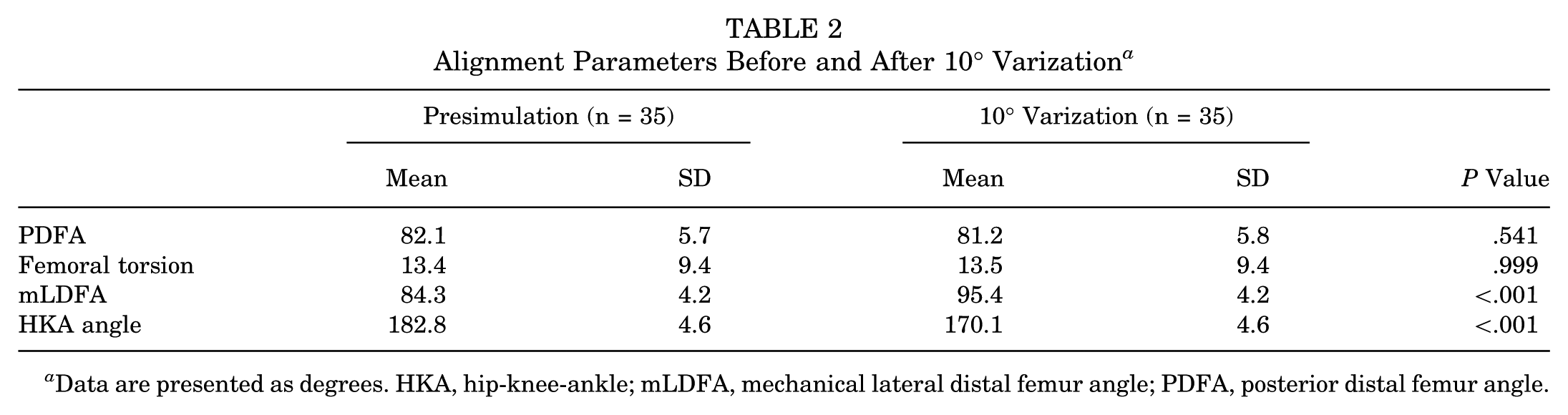
Data are presented as degrees. HKA, hip-knee-ankle; mLDFA, mechanical lateral distal femur angle; PDFA, posterior distal femur angle.
Posterior Distal Femur Angle
Axial changes of the hinge axis led to significant changes of the PDFA, while sagittal changes of the hinge axis had no effect on the PDFA (P < .001) (Appendix Table A1). A stepwise axial rotation of the hinge axis by 10° led to PDFA changes of 1.8°± 0.6° per 10° rotation at a closing angle of 10°. Anteromedial rotation of the hinge axis in the axial plane was highly positively correlated to an increase in PDFA (r = 0.99; P < .001) (Figure 4).

Changes in the hinge axis in the axial plane lead to changes of the PDFA with a linear relationship to the correction angle. Axial rotation of the hinge axis significantly influences PDFA changes when compared with the neutral hinge axis with a linear relationship to the closing wedge angle. Sagittal hinge axis rotation did not significantly influence PDFA changes. Each colored line indicates the linear regression trend for each rotation of the hinge axis. *P < .05. **P < .01. PDFA, posterior distal femur angle.
Femoral Torsion
Anterosuperiorly inclined sagittal hinge rotation was highly negatively correlated to FT changes (–0.82; P < .001) (Figure 5). No significant FT changes were observed for the rotation of the hinge axis in the axial plane at 10° varization (P = .99) (Appendix Table A1).

Changes in the hinge axis in the sagittal plane lead to changes of the femoral torsion with a negative correlation to the correction angle. Axial hinge axis rotation did not significantly influence femoral torsion changes. Each colored line indicates the linear regression trend for each rotation of the hinge axis.
Mechanical Lateral Distal Femur Angle
The mean mLDFA showed an approximately linear decrease by 1.0°± 0.07° (range, 0.8°-1.1°) per 1° varization from 1° to 15° for the neutral hinge. The decrease of the mLDFA was highly positive correlated to the closing angle (r = −0.99; P < .001).
Subgroup Analysis
Multiple linear regression on PDFA showed that axial hinge rotation is a significant factor influencing the PDFA (ß = −1.41 per 10° change; P < .001), while sagittal hinge rotation and closing angle were not factors affecting the PDFA independently in a statistically significant way. Every 10° change in axial hinge axis with a 10° varus correction led to a 1.41° mean change in PDFA.
Discussion
The most important finding of this study was that a possible neutral hinge in MCWDFO can be achieved that affects only the mLDFA and avoids unintended changes to FT or the PDFA. The PDFA changed by axial rotation of the hinge, whereas sagittal rotation had no effect on it. In contrast, FT was not affected by sagittal or axial rotation of the hinge. To alter the PDFA intentionally, an anterolateral hinge axis rotation could decrease it, and an anterolateral hinge axis could increase it. In clinical practice, osteotomy of the distal femur should be performed parallel to the femoral joint line, and incomplete posterolateral osteotomy should especially be avoided to prevent axial hinge axis rotation and thus an unintentional decrease in PDFA.
To date, factors influencing the PDFA in MCWDFO are unknown, and only sagittal changes in MCWDFO have been anticipated but not yet quantified.5,21 In HTO, incomplete posterior osteotomy, inaccurate hinge position, and inappropriate release of posterior soft tissues are described to influence sagittal alignment.27,29,36 It is difficult to accurately determine the hinge axis during surgery using conventional techniques, so virtual 3D simulations were applied to determine anatomic changes by hinge axis rotation. Virtual 3D simulation showed significant advantages as compared with conventional methods regarding quantity, precision, and reliability.19,32,35 This study demonstrates that 10° of axial hinge rotation changes the PDFA by 1.9°± 0.1° with 10° of varus correction. In HTO, posterior slope alteration of approximately 1.6° by 10° axial hinge axis rotation has been reported. 35 Factors influencing FT have not been identified, but the 3D simulation results presented in our study suggest a highly negative correlation between FT and anterosuperiorly inclined sagittal hinge rotation. Combining axial and sagittal hinge rotation may be considered to achieve optimal results in clinical cases.
Achieving an optimal hinge axis remains a challenge in clinical practice. Given the study results, it may be acceptable to modify the neutral hinge axis and perform a medial osteotomy incision orthogonal to the anatomic axis of the distal femur instead of relying on the sagittal femoral joint line, which was utilized in the present study but is difficult to determine during surgery. 30 The minimal sagittal change resulting from use of the modified hinge axis might be acceptable, as only minimal changes in FT have to be expected. However, to accomplish a true lateral hinge axis without rotation in the axial plane, a true medial osteotomy must be performed.27,36 To achieve this during the procedure, a pin placed in the mediolateral direction—aligned with the overlap of the femoral condyles under fluoroscopy—can be used for guidance, similar to techniques described for HTO. 36
The limitations of conventional surgical treatment options, particularly in terms of 3D planning, have given rise to new techniques. Notably, the development of 3D-printed patient-specific instruments has significantly advanced the precision and outcomes of knee surgery. 31 These instruments allow for more accurate planning and execution of complex surgical procedures, enabling free hinge axis planning to achieve combined varus and posterior slope corrections, which are challenging to achieve with conventional techniques. 2
Incomplete osteotomy should be avoided, as it leads to changes of the hinge axis and may occur when surgeons unintentionally perform incomplete osteotomies of the posterior cortex to reduce neurovascular complications.29,35,36 An incomplete posterior cut shifts the hinge axis anteromedially, which can lead to an unintended increase in PDFA and thus hyperextension of the knee. 6 The effects of PDFA changes on ligaments and capsule also remain unclear.
Limitations
This is theoretical research using 3D models to simulate the effects of MCWDFO on bony anatomy. Soft tissue, the surgeon factor, and possible complications are not considered. The assumption that the femur can be rotated around a hinge axis may not reflect the clinical situation, as there might be soft tissue constraints. As the data were collected anonymously, no information on body mass index or patient demographics was provided. CT scans were acquired in the supine position, which possibly affects limb alignment but reflects clinical practice.
Conclusion
With this 3D simulation study, a neutral hinge axis in MCWDFO could be found in which only coronal changes occur. By rotating the hinge axis in the axial plane, the PDFA can be significantly influenced; conversely, FT can be changed by rotation in the sagittal plane.
Footnotes
Appendix
Change in PDFA and FT After MCWDFO With a 10° Correction a

| PDFA, deg | FT, deg | |||||||
|---|---|---|---|---|---|---|---|---|
| Hinge Axis Rotation: Orientation and Magnitude | Mean | SD | Mean Δ | P Value | Mean | SD | Mean Δ | P Value |
| Sagittal b | ||||||||
| –30° | 81.5 | 5.84 | 0.63 | .99 | 18.0 | 10.1 | 4.5 | .78 |
| –20° | 81.3 | 5.83 | 0.79 | .99 | 16.4 | 10.0 | 3.0 | .99 |
| –10° | 81.2 | 5.82 | 0.88 | .99 | 14.9 | 9.7 | 1.5 | .99 |
| 10° | 81.2 | 5.76 | 0.92 | .99 | 12.2 | 8.8 | –1.3 | .99 |
| 20° | 81.2 | 5.72 | 0.88 | .99 | 10.9 | 8.4 | –2.5 | .99 |
| 30° | 81.3 | 5.68 | 0.82 | .99 | 10.1 | 7.8 | –3.4 | .08 |
| Axial c | ||||||||
| –30° | 86.9 | 5.75 | 4.79 | .001 *** | 13.8 | 9.4 | 0.4 | .99 |
| –20° | 85.0 | 5.77 | 2.95 | .270 | 13.7 | 9.4 | 0.3 | .99 |
| –10° | 83.1 | 5.78 | 1.02 | ≥.99 | 13.6 | 9.4 | 0.2 | .99 |
| 10° | 79.3 | 5.79 | –2.83 | ≥.99 | 13.3 | 9.3 | –0.1 | .99 |
| 20° | 77.5 | 5.78 | –4.63 | .282 | 13.2 | 9.3 | –0.3 | .99 |
| 30° | 75.8 | 5.77 | –6.27 | .021 * | 13.1 | 9.3 | –0.4 | .99 |
The mean changes in PDFA and FT were calculated by determining the mean difference between values obtained before and after MCWDFO with a correction of 10° according to various hinge axes as compared with the neutral hinge axis.
Differences in PDFA and FT between the various hinge axis orientations and the neutral hinge axis were statistically analyzed for overall group differences and individual pairwise comparisons. FT, femoral torsion; MCWDFO, medial closed wedge distal femoral osteotomy; PDFA, posterior distal femur angle.
Group difference: P = .999.
Group difference: P < .001.
P < .05
P≤ .001.
Final revision submitted June 16, 2025; accepted July 15, 2025.
The authors have declared that there are no conflicts of interest in the authorship and publication of this contribution. AOSSM checks author disclosures against the Open Payments Database (OPD). AOSSM has not conducted an independent investigation on the OPD and disclaims any liability or responsibility relating thereto.
Ethical approval for this study was obtained from Ludwig-Maximilians-University Munich (EC-Nr 17-044).