
Abstract
Background:
In several anatomic single-bundle anterior cruciate ligament (ACL) reconstruction (ASB-ACLR) procedures, the femoral and tibial tunnel apertures are created at different locations within the native ACL attachment area.
Hypothesis:
Graft length changes during knee motion will be different among ASB-ACLR procedures with different femoral and tibial tunnel aperture locations.
Study Design:
Controlled laboratory study.
Methods:
A total of 12 cadaveric knees were used in this study. In each knee, 4 and 3 thin tunnels were created within the ACL attachment area on the femur and the tibia, respectively. Using 1 of 5 different combinations of femoral and tibial tunnel aperture location, 5 ASB-ACLRs were performed on each knee. In each reconstruction approach, a strong thread was used in place of the tendon graft, and the tibial graft end was tethered to a custom-made isometric positioner at 0° of knee flexion, with an approximately 12-N load applied to the thread. Then, each specimen underwent 5 cycles of knee flexion-extension motion in a range between 0° and 120°, and graft length changes were determined for each SB-ACLR approach.
Results:
The length changes of the graft were significantly different among the 5 ASB-ACLRs. The maximum length change values of the 3 grafts that were implanted between the femoral and tibial centers of the posterolateral bundle attachments or implanted into the femoral tunnel created at the center of the fanlike extension fiber attachment were significantly greater than those of the graft implanted between the centers of the anteromedial bundle attachments (P < .0001) and of the graft implanted between the centers of the whole ACL attachments (P < .0001).
Conclusion:
The length changes of the graft during knee motion were significantly different among the 5 ASB-ACLR approaches, even though all of the tunnel apertures were created within the femoral and tibial attachments of the native ACL.
Clinical Relevance:
The grafts in the first 3 graft locations may be so relaxed during knee flexion that they cannot resist anterior drawer loads exerted on the tibia.
Anterior cruciate ligament (ACL) insufficiency is a serious problem for athletes. Therefore, single-bundle (SB) ACL reconstruction has been commonly performed in the clinical field. However, residual instabilities frequently remained in the SB ACL reconstruction procedures performed in the 1990s, regardless of the type of tendon graft, because the femoral tunnel outlet was created at the 12-o’clock orientation and the tibial tunnel outlet was created at the posterior part of the tibial ACL attachment. 1,2,6,13,14,23,24 To solve these problems, the concept of “anatomic” SB reconstruction was proposed, 9 based on clinical and biomechanical knowledge of anatomic double-bundle ACL reconstruction. 26,28,29
In previous studies of anatomic SB reconstruction, the femoral tunnel aperture was created at varying points on the lateral condyle. 9,11,12,21,25,27 In several studies 9,11,12,27 the femoral tunnel aperture was created at the center of the direct attachment area of the entire midsubstance fibers while the tibial tunnel aperture was created at the center of the narrow tibial attachment of the entire ACL. In contrast, Yagi et al 25 made both femoral and tibial tunnel apertures at the center of the direct attachment area of the posterolateral (PL) bundle midsubstance. Forsythe et al 4 and Shino et al 21 created the femoral tunnel aperture at the most posterior point of the posterior condyle, which was close to the joint cartilage, while the tibial tunnel aperture was created at the center of the narrow tibial attachment of the whole ACL. More recently, Kawaguchi et al 10 recommended creating both femoral and tibial tunnel apertures at the center of the direct attachment area of the anteromedial (AM) bundle midsubstance.
These femoral tunnel outlets were located apart from each other on the lateral condyle, although all of the outlets were created within the femoral attachment of the native ACL, which is wide. 17,18 Therefore, the following question about anatomic SB reconstruction arises: Do the grafts implanted into the above-described different tunnel apertures have the same function? No studies have been conducted to answer this question.
Two methods are used to evaluate ACL graft isometry during knee motion: One is to assess changes in graft length, and the other is to measure changes in graft tension. Biomechanical studies have shown a statistically significant correlation between graft length versus the knee flexion angle curve and also between graft tension versus the knee flexion angle curve in each graft. 7,8,20 In addition, a statistically significant correlation has been found between the maximum value in the length changes and the maximum value in the tension changes. 3,8,19 The length change of several grafts can be repeatedly measured in 1 knee because the measurement rarely destroys the bone tunnels or the graft fixation site. Therefore, measurement of graft length changes has been frequently used not only in basic science studies 3,7,8,19,20,22 but also in clinical studies 5,30,33 to evaluate the function of grafts reconstructed with various ACL reconstruction procedures.
We conducted a controlled biomechanical study to compare changes in graft length during knee extension-flexion among the following 5 anatomic SB reconstruction approaches under the same biomechanical conditions: namely, femoral and tibial tunnel apertures were created (1) at the center of the femoral and tibial attachments of the AM bundle midsubstance, 10 respectively; (2) at the center of the femoral and tibial attachment areas of the whole ACL midsubstance fibers, 28 respectively; (3) at the center of the femoral and tibial attachment areas of the PL bundle midsubstance, 9,11,12,27 respectively; (4) at the most posterior portion of the femoral posterior condyle, close to the cartilage margin, and at the center of the tibial attachment of the AM bundle midsubstance, respectively; and (5) at the most posterior portion of the femoral posterior condyle and at the center of the tibial attachment area of the whole ACL midsubstance, respectively. The fourth and fifth tunnel combinations were chosen to mimic the previously reported approach, 4,21 because the tibial tunnel aperture location was not precisely described. The first hypothesis was that changes in the graft length during knee flexion-extension would be significantly different among the 5 anatomic SB ACL reconstruction approaches. The second hypothesis was that the maximum length change values during the knee flexion-extension motion would be significantly different among these 5 approaches: Specifically, the maximum length change values of the grafts implanted with the third, fourth, and fifth approaches would be significantly greater than the values of the grafts implanted with the first and second approaches. The purpose of this study was to test these hypotheses.
Methods
Specimen Preparation
This study used 12 fresh-frozen cadaveric knees without evidence of any previous injury or surgery (mean age, 75.5 years; range, 67-90 years). The specimens were obtained with consent and permission from the Hokkaido University Graduate School of Medicine Anatomical Research Center. The knees were stored at −20°C and thawed before use. Each knee was thawed overnight in a refrigerator, and the biomechanical experiment was completed on the following day. The intact knee specimen was moved manually from full extension to 120° of flexion and then back to full extension for a total of 3 cycles. The tibia and femur were cut approximately 40 cm from the joint line. The skin, musculature, patella, and central part of the posterior capsule were then removed so that the tibial and femoral shafts were exposed, leaving the knee ligaments intact. The proximal part of the femur was firmly attached to a fixation apparatus so that the femur remained horizontal, while the tibia was free to allow knee motion. The AM and PL bundles of the ACL were separated by moving a thin rod proximally and distally. During the preparation and testing procedures, specimens were kept moist with water spray. Two transverse holes were created across the distal femur, avoiding the collateral ligament attachments and other stabilizing structures. The medial femoral condyle was separated with a reciprocating saw, starting between the cruciate ligaments and cutting proximally in the sagittal plane for 60 mm and then cutting medially. 32
According to recent anatomic studies, the wide femoral attachment of ACL fibers can be divided into 2 different areas: One is the direct attachment area of the ACL midsubstance fibers, and the other is the thin attachment area of the fanlike extension (FLE) fibers, which spread out from the ACL midsubstance onto the posterior condyle. 17,18 These 2 areas can be distinguished by observing the fold that is clearly formed on the femoral attachment of the ACL when the knee is flexed. 18 Drawing on these anatomic facts, Kawaguchi et al 10 reported a partition method of the wide femoral ACL attachment. In the present study, the whole attachment area of the ACL was divided into 8 partitions by use of the Kawaguchi method.
First, the outline of the whole ACL fiber attachment on the lateral intercondylar surface was marked with ink (Figure 1A). Then the direct attachment area of the entire ACL fibers was identified by flexing and extending the knee with the ACL tensed. When the knee was flexed, a distinct folding of the ACL fibers was formed at the boundary between the FLE fibers and the direct attaching midsubstance fibers, because the FLE fibers adhered to the surface of the femur. 18 This boundary line was marked with ink (Figure 1A). This line was found to be straight and parallel to the axis of the direct attachment area.

Specimen preparation. (A and B) The whole attachment area of the ACL was divided into 8 partitions according to the functional anatomy-based division method. 10 Areas A, B, C, and D comprised the fanlike extension fiber attachment area, and areas E, F, G, and H comprised the direct midsubstance fiber attachment area. (C) The center of each area on the femur was defined as points A through H. A Kirschner wire was inserted at points C, E, and H and the midpoint (point F/G) between points F and G. (D) A Kirschner wire was inserted at points 1, 2, and 3 on the tibia. Point 1 was the center of the anteromedial bundle attachment, and point 3 was the center of the PL bundle attachment. Point 2 was the midpoint between the points 1 and 3.
After the ACL attachment fibers were resected along the bone surface, 2 more straight lines were drawn according to our previous study 10 : One was drawn parallel to the boundary line, tangential to the outer edges of the FLE fiber attachment, and the other was drawn along the anterior border of the bulk of the midsubstance fibers of the ACL. Then, 5 lines were drawn parallel to the Blumensaat line: 2 were tangential to the outer edges of the ACL attachment, and the other 3 were equally spaced between the first 2 lines so that the length of the direct midsubstance fiber attachment area was divided into 4 equal parts. Thus, this method divided the whole femoral attachment of the ACL into 8 parts (Figure 1B). Areas A, B, C, and D comprised the FLE fiber attachment area, and areas E, F, G, and H comprised the direct midsubstance fiber attachment area. The center of each area was defined as points A, B, C, D, E, F, G, and H.
The tibial ACL attachment was carefully observed, and the outline of each bundle attachment was marked with ink. After each bundle was resected along with the bone surface, the center of the AM bundle attachment was marked and defined as point 1. The center of the PL bundle attachment was defined as point 3, and the midpoint between points 1 and 3 was defined as point 2 (Figure 1D). A thin tunnel was created at points 1, 2, and 3 by inserting a 2 mm–diameter Kirschner wire toward the medial aspect of the tibia. Then, the separated femoral condyles were relocated and secured with steel rods, nuts, and washers.
In each knee, we used thread grafts that mimicked 5 tendon graft placements reported in previous studies on anatomic SB ACL reconstruction. 4,9 –12,21,27,28 Polyester threads (Ti-Cron 5; Covidien Japan) having a diameter of 0.8 mm were used as the grafts, and they were so strong that none of the threads were torn during the length measurement. The 5 thread grafts, which were named H-1, E-3, F/G-2, C-1, and C-2, entailed the following different combinations of the femoral and tibial tunnel aperture locations (Figure 2). First, graft H-1 mimicked the tendon graft placement recommended for anatomic AM bundle reconstruction. 10 This thread graft was implanted through point H (the center of the femoral attachment of the AM bundle midsubstance) and point 1 (the center of the tibial attachment of the AM bundle midsubstance). Second, graft E-3 mimicked the tendon graft placement used in anatomic PL bundle reconstruction. 28 This thread graft was implanted through point E (the center of the femoral attachment of the PL bundle midsubstance) and point 3 (the center of the tibial attachment of the PL bundle midsubstance). Third, graft F/G-2 mimicked the tendon graft placement that was most frequently used in previous studies on anatomic SB ACL. 9,11,12,27 This thread graft was implanted through point F/G (the center of the femoral attachment of the entire ACL midsubstance) and point 2 (the center of the tibial attachment of the entire ACL midsubstance). Fourth, graft C-1 and graft C-2 mimicked the graft placements reported by recent studies 4,21 that recommended creating a femoral tunnel aperture at point C (the most posterior portion of the posterior condyle, which was close to the joint cartilage). In these studies, 4,21 however, the tibial tunnel aperture location was not precisely described. Therefore, in the present study, we evaluated 2 placements, grafts C-1 and C-2, which were implanted through point 1 and point 2, respectively, on the tibia.

This schematic picture shows the femoral and tibial tunnel aperture locations created in the 5 anatomic single-bundle reconstruction procedures. The femoral and tibial centers of the tunnel (H, E, F/G, and C on the femur; 1, 2, and 3 on the tibia; see Figure 1) were marked on the same photograph of the native femur–anterior cruciate ligament–tibia complex, which was taken at 0° and 90° of knee flexion, respectively. Each line shows a distance between the femoral and tibial centers. The photographs depict a cadaveric knee that was not used for the present study.
Performance of Isometric Positioner
A custom-made isometric positioner, calibrated as follows, was used to measure changes in the intra-articular thread length. The isometric positioner was composed of an outer metal cylinder, an inner metal cylinder, and a coil spring (Figure 3). The outer cylinder was fixed on the tibial cortex. The inner cylinder, to which a thread graft was tethered, could smoothly slide in the outer cylinder and indicate a change in the intra-articular thread length. The coil spring, the spring coefficient of which was 716 N/m, was installed between the outer and inner cylinders. When the length of this spring is changed by L (in meters), the force exerted to the grafted thread, F (in newtons), is explained by the following equation:

(A) A custom-made isometric positioner was composed of an outer metal cylinder, an inner metal cylinder, and (B) a coil spring. The outer cylinder was fixed on the tibial cortex. A thread graft was tethered to the inner cylinder. The coil spring, the spring coefficient of which was 716 N/m, was installed between the outer and inner cylinders. IC, inner cylinder; OC, outer cylinder; PI, position indicator.

The accuracy of the isometric positioners was evaluated with a tensile tester (PMT 250 W; Orientec). The full scale (FS) of the length measurement was 40 mm; the nonlinearity was 2% over one-half FS and 5% over FS.
Measurement Protocol
In each prepared knee specimen, the femoral end of each thread graft was fixed onto the femoral cortex with a metal button. The tibial end of each thread graft, which emerged from each tibial tunnel, remained unconstrained. We confirmed that the femur was firmly attached to a fixation apparatus so that it was kept horizontal and that the tibia was free to allow knee motion in 6 degrees of freedom (Figure 4). The knee flexion angle was measured with a custom-made goniometer, which was composed of 2 hard translucent acrylic plates (20 cm) and a hinge-type circular protractor located between the 2 plates (Figure 4). One plate was attached to the fixation device parallel to the femoral shaft so that the center of the goniometer was located at the center of the knee. The other plate was attached on the lateral part of the tibia with an elastic band.

The apparatus to fix the femur. The tibia was free to allow knee motion in 6 degrees of freedom. A hinge-type circular protractor of the goniometer was set at the center of the knee motion. The examiner manually made 5 cycles of flexion-extension motion of the tibia using a smooth rod to avoid applying any varus-valgus or rotatory forces.
Next we measured the length changes in the 5 implanted thread grafts in random order, using the isometric positioner. The tibial end of each thread graft was firmly tethered to the isometric positioner at 0° of knee flexion, applying an approximately 12-N load to the thread, while the other threads remained unconstrained. Then, the examiner manually made 5 cycles of flexion-extension motion of the tibia, using a smooth rod (Figure 4) to avoid applying any varus-valgus or rotatory forces, in a range of the flexion angle from 0° to 120° in increments of 15°, visually monitoring the goniometer. An assistant examiner read aloud the scale installed on the isometric positioner, and the graft length at each knee flexion angle was simultaneously recorded by a video camera. For this study, only the lengths at 0°, 15°, 30°, 60°, 90°, and 120° of flexion were considered. For each flexion angle, the mean length from the 5 cycles for each thread graft was calculated, and the mean value from the 12 specimens was used for statistical analysis.
A load applied to each thread graft at each angle of knee flexion by the spring installed in the isometric positioner was calculated through use of the above-described equation.
Observations of Relaxation Behavior in an Implanted Hamstring Tendon
To confirm the relaxation behaviors observed in the thread grafts studied, we reconstructed grafts H-1, F/G-2, and C-2 using a semitendinosus tendon in 3 additional knee specimens, and then we observed the amount of relaxation of each graft at 0° and 90° of knee flexion. Before each graft reconstruction, we prepared the 3 specimens in the same manner as described above for the 12 study specimens. In each ACL reconstruction, the tendon graft was secured with No. 5 polyester sutures and metal buttons on the femur and the tibia, applying an initial load of 10 N at 0° of knee flexion. After the knee flexion-extension motion was manually performed 3 times, the lateral femoral condyle was fixed onto the tibial plateau at 90° of knee flexion by inserting three 2.4-mm Kirschner wires to prevent translocation of the lateral femoral condyle on the tibia plateau. Then, we carefully translocated the medial condyle by removing the nuts and rods in order to observe the degree of graft relaxation in the lateral view.
Statistical Analysis
In each of the 12 knee specimens used in this study, we implanted 5 thread grafts representing different SB ACL reconstruction approaches, then we independently measured the length changes of each graft. Therefore, for each graft, the number of the sampled length data at each knee flexion angle was 12, which was sufficient for statistical comparisons. A 2-way analysis of variance (ANOVA) was performed to compare the length and load changes among the 5 grafts, and a 1-way ANOVA was carried out to compare the maximum length change among the 5 grafts. When a significant difference was shown among the 5 grafts, the Bonferroni-Dunn test was used for multiple comparisons. Calculations were performed with StatView 5.0 (SAS Institute). The significance level was set at P < .01.
Results
Comparison of the Length Changes Among the 5 Grafts
Figure 5 shows the relative length changes of the 5 thread grafts during knee flexion-extension. The 2-way ANOVA demonstrated that the changes in graft length were significantly different not only among the flexion angles (P < .0001) but also among the 5 grafts (P < .0001). The mean length of graft H-1 was slightly reduced with knee flexion between 0° and 30°, reaching a plateau between 30° and 120°. The mean length of graft F/G-2 was moderately reduced with knee flexion between 0° and 60°, reaching a plateau between 60° and 120° (Figure 5). The mean length of graft E-3 was greatly reduced with knee flexion between 0° and 60° and slightly increased thereafter (Figure 5). The mean lengths of graft C-1 and graft C-2 were continuously reduced between 0° and 120° (Figure 5). The post hoc test showed that the length change value for graft H-1 were significantly different from those for grafts F/G-2, E-3, C-1, and C-2 (P < .0001). In addition, the length change value for graft F/G-2 showed significant differences from those for grafts C-1 and C-2 (P < .0001). No significant differences were found in the length change values between graft F/G-2 and graft E-3 or among grafts E-3, C-1, and C-2.

Relative length changes in the 5 thread grafts. The length at 0° of knee flexion was defined as the reference length (zero). Each point and error bar shows the mean of the length change values from 12 measurements and the standard deviation, respectively. A negative value indicates a decrease in the graft length. A 2-way analysis of variance showed a significant difference not only among the flexion angles (P < .0001) but also among the 5 grafts (P < .0001). According to a post hoc test, a significant difference was found between graft H-1 and each of the other 4 grafts (P < .0001 for all) as well as between graft F/G-2 and each of grafts C-1 and C-2 (P < .0001 for both).
The maximum length change value of each graft was calculated from each graft length versus the flexion angle curve. Figure 6 shows the maximum length change values of the 5 grafts. The 1-way ANOVA showed a significant difference (P < .0001) among the 5 grafts. The post hoc test demonstrated that the maximum length change of graft H-1 (average, 3.0 mm) was significantly less than the changes of graft F/G-2 (4.6 mm; P = .0024), graft E-3 (5.9 mm; P < .0001), graft C-1 (6.8 mm; P < .0001), and graft C-2 (6.7 mm; P < .0001). The maximum length change of graft F/G-2 was significantly less than the changes of graft C-1 and graft C-2 (P < .0001 for both). No significant differences were found in the maximum length changes between graft F/G-2 and graft E-3 or among graft E-3, graft C-1, and graft C-2 (Figure 6).
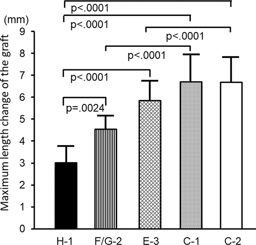
Comparison of the maximum length change among the 5 thread grafts. Each bar and error bar shows the mean of 12 measurements and the standard deviation, respectively: graft H-1 (3.0 ± 0.8 mm), graft E-3 (5.9 ± 1.0 mm), graft F/G-2 (4.6 ± 0.6 mm), graft C-1 (6.8 ± 1.5 mm), graft C-2 (6.7 ± 1.2 mm). A 1-way analysis of variance showed a significant difference (P < .0001) among the 5 grafts. The results of the post hoc test are shown in the graph.
Comparison of Load Changes Among the 5 Grafts
Figure 7 shows changes in the loads applied to the 5 thread grafts by the spring installed in the isometric positioner. The 2-way ANOVA did not show any significant differences among the flexion angles or among the 5 grafts. In each graft, the load was highest at full extension, with a similar range between 12 and 15 N. The load was slightly reduced with knee flexion between 0° and 30°, reaching a plateau (approximately 12 N) between 30° and 120° (Figure 7).
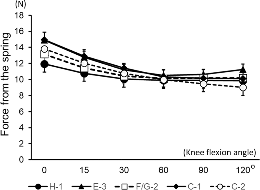
Changes in the load applied to each thread graft by the spring installed in the isometric positioner. A 2-way analysis of variance did not show any significant difference among the flexion angles or among the 5 grafts.
Observations of Relaxation Behavior in an Implanted Hamstring Tendon
At 90° of knee flexion, graft H-1 using the semitendinosus tendon was almost tense and graft F/G-2 was slightly loosened, while graft C-2 was extremely slack (Figure 8). After the medial condyle was reduced and fixed again with the nuts and rods, the observation at 0° of knee flexion was made in the same manner. The results showed that each tendon graft was tense at 0° of flexion but it was relaxed to different degrees at 90° (Figure 8). This observation supported the length data compiled from the thread grafts.

To confirm the length data from the thread grafts in the study, we made experimental observations of grafts H-1, F/G-2, and C-2 at 0° and 90° of knee flexion, using a semitendinosus tendon in 3 additional knee specimens. At 0° of knee flexion, each tendon graft was tense. At 90° of knee flexion, graft H-1 was mostly tense and graft F/G-2 was slightly loosened, while graft C-2 was extremely slack.
Discussion
The present study demonstrated, first, that changes in graft length during knee flexion-extension were significantly different not only among the flexion angles studied but also among the 5 graft placements studied. Second, the maximum length change values were significantly different among the 5 study grafts. Namely, the maximum length change of graft H-1 was significantly less than the changes of the other grafts. In addition, the maximum length change of graft F/G-2 was significantly less than the changes of grafts C-1 and C-2. These results suggest a strong possibility that changes in graft length during knee flexion-extension are significantly different among the 5 anatomic SB ACL reconstruction approaches previously reported. 1,9 -12,21,27,28 For example, the maximum length change values of grafts implanted with the 3 SB procedures in which a femoral tunnel aperture is created at the center of the direct attachment area of the PL bundle midsubstance or at the most posterior portion of the posterior condyle, may be significantly greater than the values for grafts implanted with the other 2 SB procedures, in which a femoral tunnel aperture is created at the center of the direct attachment of the AM bundle midsubstance or at the center of the direct attachment area of the entire ACL midsubstance fibers. To date, all 5 of these procedures are called “anatomic SB ACL reconstruction” because the grafts are implanted into the bone tunnels that are created within the native ACL attachments. However, the present study suggests that the ACL grafts reconstructed with these procedures function differently. Therefore, orthopaedic surgeons who perform these ACL reconstruction procedures should have precise knowledge of the different biomechanical functions of the tendon grafts that are implanted.
In the present study, the graft length changes were measured because the length measurement has a few advantages, as described above. An additional advantage is that length changes can be measured repeatedly in several grafts that have different attachments in a cadaveric specimen without destruction of the bone tunnels or the fixation sites. Namely, in the present study, we could create 4 and 3 thin tunnels in the femur and the tibia, respectively, in each knee specimen, and we could repeatedly measure the length changes of the 5 thread grafts under the same biomechanical conditions. In none of the knee specimens were the bone tunnels broken throughout the experimental measurement. Therefore, we could make sufficiently powered statistical comparisons of the length data among the 5 grafts, even though we used only 12 cadaveric specimens. Namely, we gathered 12 data points regarding length at each angle of knee flexion, which was enough to make statistical comparisons with a high significance level (P < .01).
We considered why the maximum length change values of grafts C-1 and C-2 were significantly greater than those of grafts H-1 and F/G-2. It is known that the posterior condyle is almost circle-shaped in the lateral view. 17,18,28 Point C is located at the most posterior portion on the posterior condyle, which was close to the cartilage margin, as shown in Figure 1. Previous anatomic studies have indicated that the distance between point C and point 1 at the full extension position is the longest in the 5 grafts and that the distance between point C and point 2 is the second longest. 10,17,18 It is common knowledge that the posterior condyle rolls on the tibial plateau with a slight sliding movement. 18 Therefore, when the knee is flexed to 90°, the distance between point C and point 1 and the distance between point C and point 2 are the shortest among the 5 grafts. Subsequently, the maximum length change values of grafts C-1 and C-2 may be greatest among the 5 grafts at 90° of flexion. In contrast, points H and F/G are located near the center of the circle-shaped posterior condyle. 17,18,28 Therefore, when the knee is at 90° of flexion and the posterior condyle rolls on the tibial plateau, the distance between point H and point 1 or between point F/G and point 2 hardly changes. These facts explain why the maximum length change values of grafts C-1 and C-2 were significantly greater than those of grafts H-1 and F/G-2.
As for clinical relevance, the present study has provided important information to the following debate 10,22 : Which graft is more appropriate for SB ACL reconstruction, the so-called isometric graft or the anisometric graft? The present study showed that the anisometric grafts (grafts E-2, C-1, and C-2), were so relaxed in knee flexion that they could not resist anterior drawer loads exerted on the tibia, while the degree of relaxation was less in the relatively isometric grafts (grafts H-2 and F/G-2). We believe that the implanted tendon graft should contribute to knee stability not only in knee extension but also in knee flexion. Therefore, we consider that in anatomic SB reconstructions, it is necessary to implant a relatively isometric graft, such as grafts H-2 and F/G-2, in order to reconstruct a knee that is stable in both flexion and extension. However, we cannot provide a definite recommendation for clinicians based solely on a biomechanical study. Further biomechanical and clinical studies are therefore needed.
This study had some limitations. First, we applied a relatively low tension of approximately 12 N. However, biomechanical studies have recommended that such low tension be applied to the graft in ACL reconstruction. 15,16,31 Therefore, we considered that the biomechanical parameters in the present study were acceptable to compare graft function in the 5 anatomic SB reconstruction approaches we evaluated. Second, because the diameter of the thread graft used in this study was thin (0.8 mm), we cannot refer to the length changes of the thick tendon graft in the ACL-reconstructed knee. However, a thin thread graft has been commonly used in many length measurement studies, 3,5,7,8,19,20,22,30,33 because a thick graft can hardly move within a bone tunnel due to the high friction force between the graft surface and the tunnel wall, so that it is difficult to precisely measure length changes of the graft. Therefore, we believe that the study design using the thin thread graft is acceptable for a biomechanical length measurement study.
A third limitation is that we did not measure changes of tension in the 5 grafts after the ACL reconstruction. However, it is difficult to repeatedly measure the graft tension in a single knee specimen because the tense graft enlarges or destroys the tunnel aperture. Therefore, to measure tension changes of the 5 grafts, we should conduct a large biomechanical study using many knee specimens (ie, 60 specimens, 12 for each of the 5 grafts) in the future. Fourth, some limitations were imposed by the use of cadaveric knee specimens. Fifth, we did not measure any of the graft length changes during rotating or pivoting knee motion. Sixth, quadriceps and hamstring muscle forces were not applied to the knee specimens. Seventh, the measurements were not performed under the actual conditions in which the ACL is loaded, such as simulated pivot-shift test, anterior tibial translation, and weightbearing. Eighth, we could not obtain cadaveric knee specimens from young donors. Beyond these limitations, however, we believe that the present study provides new biomechanical information concerning anatomic SB ACL reconstruction.
Conclusion
In the present study, we compared length changes of 5 thread grafts that were placed in different combinations of femoral and tibial tunnel aperture locations. The results demonstrated that changes in graft length during knee flexion-extension were significantly different among the 5 grafts. Further, the maximum length change values were significantly different among the 5 grafts. Namely, the maximum length change of graft H-1 was significantly less than that of the other grafts. In addition, the maximum length change of graft F/G-2 was significantly less than that of grafts C-1 and C-2. To date, all of the SB reconstruction approaches to implant these grafts have been called anatomic SB ACL reconstruction. However, the present study suggests that the ACL grafts reconstructed with these approaches have different functions.
Footnotes
One or more of the authors has declared the following potential conflict of interest or source of funding: The threads and fixation devices used in this study were donated by Smith & Nephew Endoscopy Japan. AOSSM checks author disclosures against the Open Payments Database (OPD). AOSSM has not conducted an independent investigation on the OPD and disclaims any liability or responsibility relating thereto.
Ethical approval for this study was obtained from/waived by the institutional review board of Graduate School of Medicine, Hokkaido University.