
Abstract
Purpose:
The objective of this study was to improve the three-dimensional (3D) understanding of optimal lateral cortical hinge in medial open-wedge high tibial osteotomy (MOWHTO) via a computational cadaveric simulation of actual size.
Methods:
The computed tomography data of 117 adult cadavers were imported into Mimics® software to design 3D models of tibia and fibula. To simulate the MOWTHO, a virtual cutting plane was developed inside the safe zone based on established landmarks. After splitting and distracting through the cutting plane, the 10-mm cylinder (Ø 30 mm; height 10 mm) was placed vertically to be occupied properly in the nonosteotomized lateral cortex. The cross points between the round cylinder and cutting plane represented the anterior and posterior hinge points, which were used to validate the 3D position and direction of cortical hinge.
Results:
A 10-mm cylinder did not violate the proximal tibiofibular joint (PTFJ) and the protruding segment of the condylar area was less than 2 mm in 115 models. The connecting line between anterior and posterior hinge points was an average of 12.1° (range 0–24.1°, SD 4.64) to the lateral side. In the nonoverlapping anteroposterior projection between proximal fibula and tibia, the posterior hinge point was laid over the PTFJ as close as possible. Based on free 360° rotation and magnification without any tilt, no posterior cortical disruption of PTFJ was observed while securing a minimum width of 10 mm.
Conclusion:
If the posterior hinge point was placed immediately above the PTFJ without involvement, the nonosteotomized portion carried sufficient width greater than 10 mm, despite lateral rotation at an average hinge direction of 12.1°.
Introduction
With the introduction of plate fixator for high tibial osteotomy in 2003, 1,2 the medial open-wedge high tibial osteotomy (MOWHTO) represents a reliable treatment method for medial compartmental osteoarthritis with varus deformity in young and active patients. 3 It was preferred more than the closed technique due to its higher primary stability and lower morbidity. 4 Over time, several important advances to this technique have been introduced to prevent complications, including lateral hinge fracture, change of posterior tibial slope, and discomfort associated with plate protrusion. In MOWHTO, the opposite structure lateral to the cortical hinge points, including the lateral cortex, soft tissue of femorotibial lateral capsule–periosteal sleeve, and proximal tibiofibular joint (PTFJ), represents an important constraint, which resists tensile forces acting at the wedge-distracted site after medial plate fixation. 5 These structures should be maintained until the distracted gap is filled with new bone. The integrity and width of nonosteotomized osseous portion (lateral cortical hinge) are especially important factors for intraoperative control by surgeons.
To maintain the integrity of lateral cortical hinge from opening osteotomy to completion of gap healing while preventing loss of wedge-distracted correction, most surgeons intend to localize a cutting plane of osteotomy inside the safe zone within the proximal one-third of the fibular head in the anteroposterior (AP) projection of image intensifier. 5 –8 To maintain a safe zone for wedge-distracted correction, the position and direction of anterior and posterior cortical hinge points are crucial for the success of MOWHTO, at least in principle. The anterior and posterior endpoints of osteotomy and cutting plane should be intraoperatively verified by the correct intensifier view and the width of lateral cortical hinge should be adequate to prevent intraoperative lateral hinge fracture. Therefore, most surgeons use the overlapping area of fibular head with lateral tibial condyle as a reference point by rotating the leg 30° internally, regardless of patient-specific anatomy. 5 Considering that the exact placement of cutting plane and cortical hinge points is technically demanding owing to projection error and anatomical complexity of proximal tibia close to neurovascular structures, a three-dimensional (3D) understanding of safe zone for precise osteotomy is a prerequisite for obtaining the highest outcomes associated with MOWHTO. However, to the best of our knowledge, no study has conducted a 3D analysis of safe zone and lateral cortical hinge by simulating the wedge-distracted osteotomy at actual size. Therefore, the objectives of this 3D simulation study are to improve the 3D understanding of lateral cortical hinge for MOWHTO via comparison with PTFJ and to demonstrate the usefulness of established landmarks for verification of the accuracy of cutting plane and hinge points.
Materials and methods
Digital human data were collected from the Korean Institute of Science and Technology Information and used with permission. The cadavers, which showed leg or adjacent joint problems based on a review of records, were excluded and 117 adult cadavers (59 males and 58 females) were enrolled. The mean age of these cadavers was 54.8 years (range 21–86 years; SD 11.38 years) and the mean height was 160.8 cm (range 146–176 cm; SD 7.28 cm). The whole body of each cadaver underwent continuous scans at a thickness of less than 1 mm (87 cadavers; Pronto, Hitachi, Japan, 30 cadavers; Definition AS+, Siemens, Germany) in supine position. All the computed tomography (CT) data in Digital Imaging and Communications in Medicine format were imported into Mimics® software (Materialise Interactive Medical Image Control System; Materialise, Antwerp, Belgium). To reconstruct 3D models of the tibia and fibula and their medullary canal (3D tibia model), the Mimics® (Version 22) software was used. The talus and distal femur were removed to facilitate 3D rendering. A TomoFix® model (DePuy Synthes, Co, West Chester, Pennsylvania, USA) in stereolithograph format was created using a 3D sensor (Comet5®; Carl Zeiss, Steinbichler, Germany) at actual size to simulate the MOWHTO in the proximal tibia.
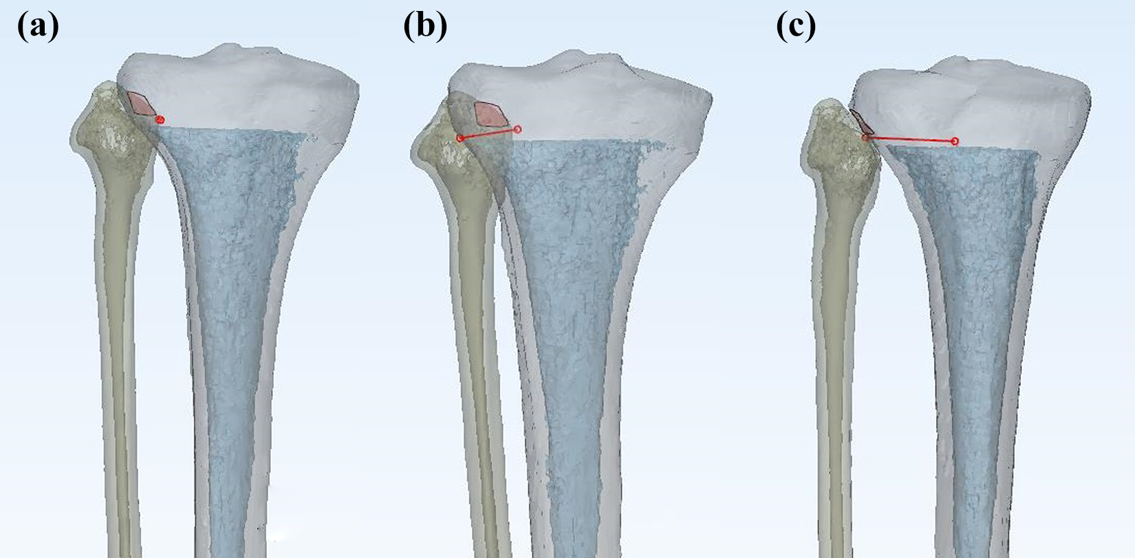
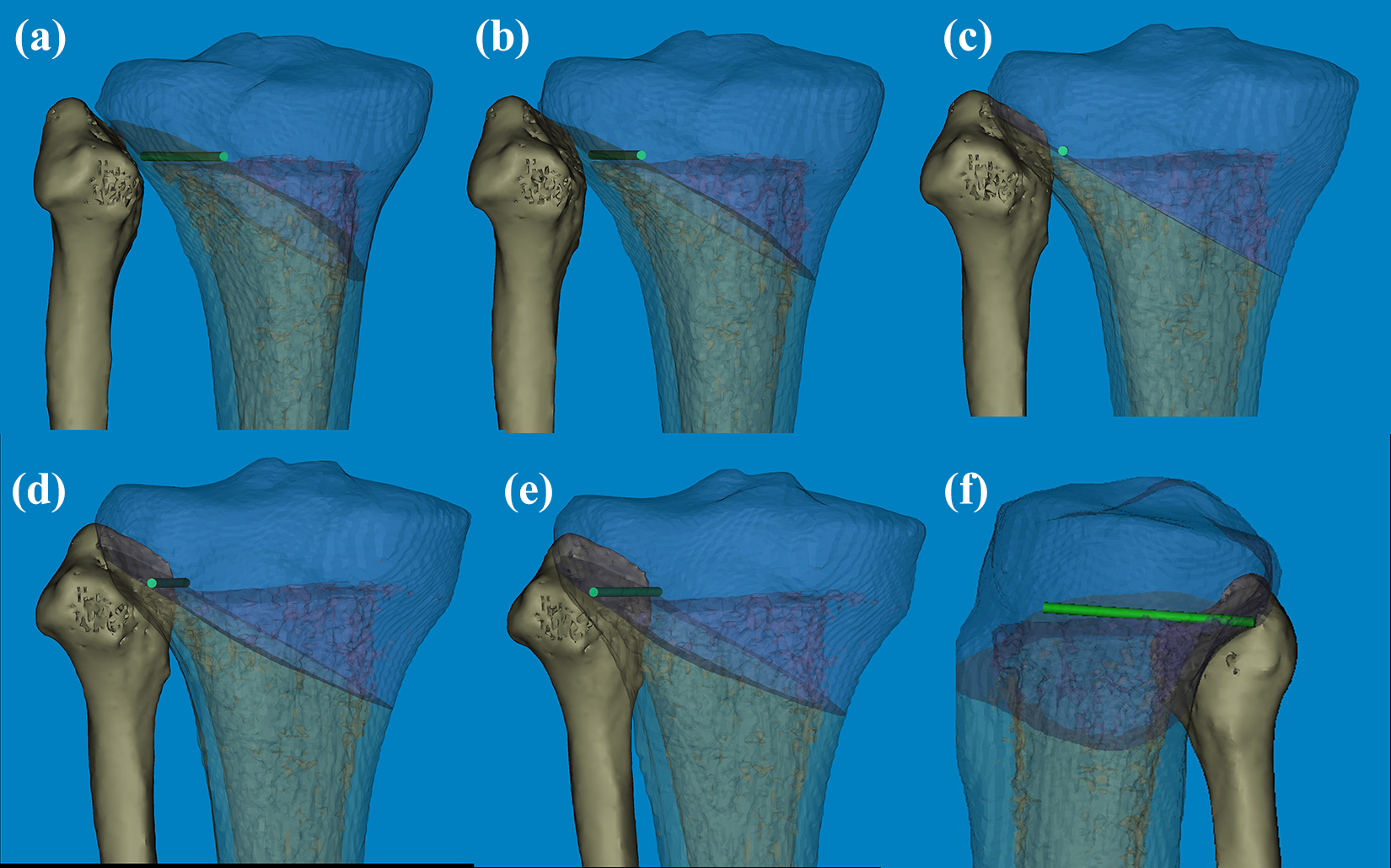
To design the MOWHTO simulation model, the cutting plane of osteotomy was derived using the Mimics® software tools. In the standard AP projection, 5,9 the lateral exit of virtual cutting plane was placed immediately distal to the fibular tip inside the safe zone. 5 –8,10 –14 The starting point of the medial surface was distal to the tibial tubercle considering the Tomofix® hole D, and the virtual line was parallel to the tibial slope in the sagittal plane to prevent a change in tibial slope 2 (Figure 1). To ensure the width of lateral cortical hinge not less than 10 mm, a round cylinder measuring 30 mm in diameter and 10 mm in height (10-mm cylinder) was used. Based on the well-known landmarks, 5,8,9 a 10-mm cylinder was placed vertically in the nonosteotomized lateral cortex using the following method (Figure 1): (1) The posterior hinge point was marked in the medial end of articular facet inside the safe zone to avoid the injury of PTFJ. (2) The posteromedial border of 10-mm cylinder was exactly aligned to be matched with posterior hinge point. (3) In the axial plane, the 10-mm cylinder was rotated inward with respect to the posterior hinge point until the anterolateral border of 10-mm cylinder was matched with the cortex of the proximal tibia. (4) The anterior hinge point was marked as the point of intersection between the anteromedial border of 10-mm cylinder and the cutting plane. The line connecting the anterior and posterior hinge point was defined as a hinge line. The position and direction of the hinge line corresponded to the lateral cortical hinge in the wedge-distracted osteotomy (Figure 1). Finally, after confirming the two hinge points and the direction of hinge cylinder, the definitive positions of lateral cortical hinge and TomoFix® were refined and validated by an experienced surgeon (corresponding author and first author).

In the 3D model of tibia and fibula, (a) the cutting plane is immediately inferior to the tip of fibular head in the neutral AP projection. (b, c) Although the TomoFix® was attached on the medial side of proximal tibia to achieve the maximal length of osseous purchase, there was a significant gap between them in the osteotomized area. (d, e) The posterior hinge point was marked in the medial end of articular facet inside the safe zone to avoid the injury of PTFJ. The posteromedial border of 10-mm cylinder* was exactly aligned to be matched with posterior hinge point†. (f) In the axial plane, the 10-mm cylinder was rotated inward with respect to the posterior hinge point† until the anterolateral border of 10-mm cylinder was matched with the cortex of the proximal tibia. The anterior hinge point‡ was marked as the point of intersection between the anteromedial border of 10-mm cylinder and the cutting plane. The line connecting the anterior and posterior hinge point was defined as a hinge line (red line) and the angle was measured based on the tangent line (black line). *10-mm cylinder (30 mm in diameter and 10 mm in height). PTFJ: proximal tibiofibular joint; AP: anteroposterior.
To evaluate the efficacy of the 10 mm rule for the lateral cortical hinge, the overhanging portion over the 10-mm cylinder was confirmed by magnifying the region of interest. Based on the width of the overhanging portion, the following three groups were assigned (Figure 2): the neutral model (group), less than 2 mm; (2) the negative group, less than 3 mm; and (3) the positive group, more than 2 mm. All data are presented as mean and range or mean and standard deviation. Correlations between variables were evaluated using Pearson correlation analysis. Subsequently, univariate and multivariate regression analyses were conducted to evaluate the association between variables. Statistical significance was set at p <0.05. All statistical analyses were performed using SPSS statistical software package for Windows (version 25.0).

In the axial plane, the overhanging portion over the 10-mm cylinder was measured and the following three groups were assigned: the neutral model (group), less than 2 mm; (2) the negative group, less than 3 mm; and (3) the positive group, more than 2 mm.
Results
The 3D analysis demonstrated that the articulation of PTFJ corresponded to the fibular depressed area, which was the safe zone in wedge-distracted osteotomy. By reformatting the plane of CT scan along the hinge line, the lateral cortical hinge of 10 mm always included the PTFJ without violating the articular facet of PTFJ in the axial or the coronal plane (Figure 3). Despite the close proximity of PTFJ, we found that the posterior hinge point showed sufficient width of lateral osseous bridge at more than 10 mm (Figure 3). In the caudal projection of the proximal-plateau fragment, the hinge line slightly pierced the nonarticulating portion of the fibular head. However, the articular facet of fibular head was not violated. The overhang over 10-mm cylinder in the lateral cortical hinge was analyzed using 115 models of neutral groups and 2 models of the negative group. However, no positive group was found. In models assigned to the negative group, the overhanging part of the 10-mm cylinder was the most prominent area of the lateral condyle. None of the models carried any negative portion involving the posterior condylar area around PTFJ. Based on free 360° rotation and magnification without any tilt, no posterior cortical disruption of PTFJ was observed while securing a minimum width of 10 mm.

By reformatting the CT scanning plane along the hinge line, the 10-mm lateral cortical hinge included the PTFJ without violating the articular facet of PTFJ in the axial, coronal, sagittal, and 3D biplanar images. *Osseous bridge measuring 10 mm in width. PTFJ: proximal tibiofibular joint; CT: computed tomography.
The hinge line was nearly vertical to the ground when the tibial tubercle was directed to the superior plane (Figure 1). Compared with the tangent line of the posterior condylar margin, the direction of hinge line was slightly rotated laterally (Figure 1). The average angle of hinge line was 12.1° (range 0–24.1°, SD 4.64°). When the hinge line was aligned to the anterior and posterior ends by rotating the 3D models medially (matched AP projection), the overlapping points of all models between fibular head and lateral cortical margin were placed within 2 mm of the fibular tip. The overlapping point of 76 (65.0%) models was accurately aligned in the fibular tip while it was aligned medial and lateral to the tip in 35 (30.0%) and 6 (5.0%) models, respectively (Figure 4). In the statistical analysis of the overlapping point (fibular tip or not), the angle of hinge line was negatively correlated with variables of the overlapping point through point biserial correlation (r = 0.253, p = 0.006). A series of one-way analysis of variance revealed a significant effect of an overlapping point on the angle of hinge line. Specifically, models with higher angles were likely to carry the overlapping point in the medial side (F = 4.341, p = 0.015).
(a) When the hinge line was aligned to the anterior and posterior ends by rotating the 3D models medially (matched AP projection), the overlapping points of all models between fibular head and lateral cortical margin were placed within 2 mm of the fibular tip and the articular surface between fibula and proximal tibia became smaller. (b) When the overlapping point was lateral to the fibular tip, the articular surface could be observed as much as possible. (c) In the nonoverlapping projection, the articular surface was observed linearly, and the posterior hinge point could be seen as close as possible. AP: anteroposterior.
Discussion
The surgical complications of MOWHTO are inversely correlated with the number of operations performed. To prevent intraoperative complications including lateral hinge fractures and attain favorable outcomes, a sufficient width of the lateral cortical hinge is needed to prevent fracture during wedge distraction and maintain its position until the distracted site is filled with new bone. This computational simulation was performed to improve the 3D knowledge of the lateral cortical hinge and determine the usefulness of established landmarks 5,10,12,15,16 for validation of the accuracy of cutting plane and hinge points. The study demonstrates the following several findings not detected on intraoperative or postoperative images: (1) The general rule of 10 mm for lateral cortical hinge was safe to implement. (2) Despite the close proximity between the posterior hinge point and PTFJ, there was no violation of the 10 mm rule by the joint surface. (3) When the hinge line was aligned with the anterior and posterior ends, the overlapping point was located within 2 mm of the fibular tip and termed as matched AP projection. Furthermore, to visualize the posterior hinge point clearly, the fluoroscopic AP projection was obtained intraoperatively to ensure that the fibular head is not overlapped with tibia by rotating the leg medially and is termed as nonoverlapping AP projection.
Considering that the two hinge points and their connecting direction represent the orientation of the lateral cortical hinge, 10,11,14,16 –18 the precise locations of the two hinge points are key factors that can be controlled surgically. As a rule, osteotomy should leave 10 mm of intact lateral cortex at both sides and the connecting line between the two hinge points may be located on the lateral side but not the posterolateral side. 5,14 Besides, a posterior hinge point of the osteotomy should not violate the PTFJ to resist the shearing force acting on the wedge-distracted site after medial plate fixation. 5 To meet these conditions, in this study, a 10-mm cylinder was vertically placed in the lateral edge of the plateau to distract the distal-shaft fragment for simulation of the MOWTHO. Based on these virtual simulations of the lateral cortical hinge, we demonstrated that its direction was shifted slightly to the lateral side according to the posterior condylar axis for keeping the general rue of 10 mm for the lateral cortical hinge. Recently, based on a retrospective case-control study, Ogawa et al. 12 and Wang et al. 18 classified osteotomy types along the coronal and axial planes by analyzing the relationship between the lateral hinge fracture and osteotomy level. They emphasized the role of sufficient osteotomy without involving the medial edge of fibular head and recommended a lateral direction of the nonosteotomized osseous bridge, although the safe angle was not described. 10,14 However, using this computational simulation, we found that an angle of 12.1° was acceptable to secure sufficient osseous bridge without involving PTFJ. If the hinge direction was 12.1° to the lateral side or vertical to the tangent line to the posterior condylar axis, the osseous width of nonosteotomized bone was always greater than 10 mm.
The optimal nonosteotomized bone (lateral cortical hinge) is based on accurate assessment of posterior hinge point via improved intensifier view of AP projection, since the amount of tibial rotation has been shown to affect the visualization of posterior hinge point. Therefore, it is important that the optimal AP projection of knee is used to determine the position of posterior hinge point (Figure 5). Despite normal torsional alignment of tibia, the degree of internal rotation of the leg is currently unknown. Therefore, a few studies 5,10,16 reported that the degree of overlap between tibia and fibula may be used in AP projection, because the proximal plateau fracture should include PTFJ as an important constraint to prevent surgical injury associated with wedge-distracted osteotomy. Han et al. 5 suggested that the leg should be internally rotated to 30° to identify the optimal hinge point. Agneskirchner et al. 1 also recommended that the leg should be internally rotated to locate the patella accurately and anteriorly. In this study, we differentiated fluoroscopic AP projections useful for wedge-distracted osteotomy. We developed and classified the AP projections for MOWHTO: (1) matched AP, (2) nonoverlapping AP, and (3) neutral AP projection in which, during tibial torsion, the tibia was rotated and the lateral cortical margin divided the fibula in half approximately. 19
(a) Considering the degree of internal rotation, the nonoverlapping AP projection is the optimal view of posterior hinge point. (b–f) The relationship between fibular tip and hinge cylinder identified to determine the precise location depending on the degree of leg rotation could be seen. AP: anteroposterior.
Compared with the internally rotated projections, 8,16,18,19 the tibia model should be more internally rotated to obtain matched AP projection. Considering that the neutral AP projection in which the overlapping point was lateral to the fibular tip, 19 the overlapping points of matched AP projection were placed within 2 mm of the fibular tip and accurately aligned with the fibular tip. A total of 111 models (95%) had the overlapping point medial to the fibular tip. Compared with the fibular bisector line, which was imaginary and approximate in neutral AP projection, our fibular tip landmark and overlapping point enabled our validation of the degree of tibial rotation without additional support. As described above, the close proximity between the posterior hinge point and PTFJ was best demonstrated by nonoverlapping AP projection, which was rotated more to the medial side. Thus, these three AP projections (neutral AP, matched AP, and nonoverlapping AP projection) can be used intraoperatively to prevent osteotomy-related complications via precise localization of the posterior hinge point (Figure 6).

Three AP projections, including (a) nonoverlapping AP, (b) neutral AP, and (c) matched AP projection, show the relationship between posterior hinge point and safe zone. AP: anteroposterior.
However, this computational simulation study has several limitations. First, a very simplified model was used without involving the surrounding soft tissue. Second, all measurements were obtained from normal tibiae not indicated for MOWHTO. In addition, our results had rather descriptive features without clinical evaluation. Third, the hinge points and cutting plane were placed manually using tools in the Mimics® software suggesting intra- and interobserver errors. Nevertheless, our demonstration based on computational simulation had several strengths. Our simulation under actual size not only validated the advantages of established landmarks but also improved our understanding of the 3D view about the safe location of optimal cutting plane and hinge points. The results suggest the need for technical innovations to minimize intraoperative complications associated with lateral hinge fracture.
Conclusion
Compared with fibular bisector line, the fibular tip as the overlapping point may be used to assess the tibial rotation and validate the cortical hinge points and direction in the AP projection of MOWHTO. In the nonoverlapping AP projection, the proximity between the posterior hinge point and PTFJ was demonstrated adequately. To maintain an optimal width (10 mm) and direction of the lateral cortical hinge (nonosteotomized osseous bridge), the posterior hinge point should be placed immediately above the PTFJ without violation and closely in the nonoverlapping AP projection. The hinge line should exhibit an average angle of 12° to the lateral side.
Footnotes
Declaration of conflicting interests
The author(s) declared no potential conflicts of interest with respect to the research, authorship, and/or publication of this article.
Funding
The author(s) disclosed receipt of the following financial support for the research, authorship, and/or publication of this article: This study was supported by research funds from Dong-A university.