
Abstract
Objective:
Tibiofemoral geometries in a total knee replacement (TKR) affect the performance of an implant during activities of daily living. The specially shaped components of a surface-guided TKR aim to control the tibiofemoral motion, such that a normal pattern of motion is achieved, even at high flexion angles. The purpose of this study was to assess the influence of the design parameters on the kinematic behavior of such an implant. A combination of design variables was determined that resulted in the least deviation from the design kinematic target.
Methods:
Six major design variables were considered to generate customized surface-guided TKR candidates. The contribution of these variables was evaluated by principal component analysis considering the input design variables and the results of the kinematic performance from a virtual simulation of deep squatting. The tibial internal–external rotation and the anterior–posterior translation of the medial and lateral femoral condyles were recorded for each design candidate. A quantified objective function of the kinematic behavior was used to define the design with a maximum agreement with the target pattern of motion.
Results:
The location and orientation of the flexion–extension axis and the tibial slope were the most contributing parameters on the modes of variation. On the other hand, the conformity between the lateral guiding arcs had the least contribution.
Conclusion:
Virtual simulation showed that the current TKR reached deep flexion angles under squat load, while the tibia pivoted around the medial center. The tibial rotation was within the expected range of the IE rotation from healthy joints.
Introduction
With an increasing number of younger and more active patients who require knee arthroplasty, 1 the capability of an implant to achieve a high range of flexion has become an important design feature. The maximum knee flexion in a total knee replacement (TKR) with less risk of impingement between the posterior femoral condyle and the tibial insert at deep flexion angles is reported to be affected by the anterior–posterior (AP) location of the femur, which is related to the design of the tibiofemoral components. 2
The concept of a surface-guided TKR is to guide the motion of the femur on the tibia based on a desired target path of tibiofemoral contact points. 3,4 The geometric design features of the articulating surfaces in a surface-guided TKR provide the rollback motion of the femur as the knee flexes, with no need for an intercondylar mechanism. 4 –6 For the TKR of this study, such guidance of the motion is provided through incrementally changing radii of two tangent inner and outer guiding arcs on the lateral side, while the distance between the medial and the lateral contact points remains constant. 5,7 In this design, there is a medial partial ball and socket configuration, which provides a stable medial pivot center. 7 It is believed that different geometric design variables affect the kinematic performance of this surface-guided TKR.
For a typical TKR, various parameters affect the kinematic outcomes including the geometric design variables, alignment of the components, and the patient specific requirements and conditions. 8 –10 Previous studies used different computational methods to analyze the influence of design factors, including the radii of the femoral component in the sagittal and the frontal planes, the slope of the tibial insert, and the conformity between articulating surfaces. 8,9,11,12 Fitzpatrick et al. 9 reported that design factors, such as the distal and posterior radii of the femoral condyles and the tibial insert slope, are critical parameters affecting the performance of a TKR at deep flexion angles.
A combination of the finite element analysis and probabilistic and principal component analysis (PCA) methods have been previously used to investigate the effect of different design and surgical- or patient-specific factors on the kinematic and wear performance of TKR designs. 8,10,12 –14 PCA defines the relation between all parameters, including input variables and outcome measures collectively. For instance, Fitzpatrick et al. 13 implemented PCA combined with a probabilistic analysis using a finite element model to analyze the influence of alignment and loading conditions on patellofemoral kinematics after TKR. They reported that the analysis of the modes of variation based on PCA provided a complete understanding of the interrelation between parameters (inputs and outputs), which was not possible by traditional sensitivity analysis. 13
The first objective of this study was to quantify the influence of six major design parameters of a customized surface-guided TKR 7 by PCA. In this analysis, the outcome variables were the incremental internal–external (IE) rotation of the tibia and the AP translation of the medial and the lateral femoral condyles, which were measured from a virtual simulation of deep squatting. Second, the outcomes of the parametric kinematic analysis from virtual simulations were used to identify the combination of geometric design variables with optimum kinematic performance. For the parametric study, a kinematic objective function was considered, which represented and quantified the kinematic behavior of each TKR design candidate in comparison to the desired target pattern of motion.
Material and methods
The anatomic tibial and femoral geometries were extracted from a magnetic resonance image (MRI) data provided in the studies by Guess, Bloemker, and colleague.
15
–17
The computer aided design models of the femoral and tibial components of a TKR were generated based on the surface-guided concept and the 3D geometries of the patient’s knee joint.
4,5,7
A previously developed design criterion
7
was used to generate the customized surface-guided TKR of this study. This TKR is featured by particular guiding features implemented on the medial and lateral tibiofemoral condylar surfaces: incrementally changing radii of the lateral tibiofemoral contact arcs at different increments of the flexion angle, medial partial ball and socket configuration, and constant distance between medial and lateral contact points at different interval of flexion of the joint.
Principal component analysis
Six major geometric design variables were considered as the input variables to parameterize the design of the tibiofemoral components (Figure 1 and Table 1):
sagittal slope of the medial tibial plateau (X1), radius of the lateral sphere (X2), AP location of the medial and lateral centers of the femoral condyles (X3 and X4), radius of the partial medial sphere (X5), and conformity between the tibial and femoral lateral guiding arcs (X6).

Geometric design parameters of the surface-guided TKR. (a) R m is the radius of the medial sphere (X5 ), and C m and C l show the locations of the centers at the medial and lateral femoral compartments (X3 and X4 ). (b) Medial sagittal view. (c) The trace of the contact points is resulted from the projection of the sagittal plane contact points on the lateral sphere. R l is the radius of the lateral sphere (X2 ), which affects the trace of the tibial and femoral contact points. The tibial insert has a sagittal slope on the medial compartment (X1 ). (d) r fi and r fo are radii of the inner and outer femoral guiding arcs, and rti and rto are the radii of the corresponding tibial guiding arcs. The difference between the radii of the lateral guiding arcs on the femoral and tibial parts was another design variable (X6 ). TKR: total knee replacement.
Design variables for the customized surface-guided TKR.
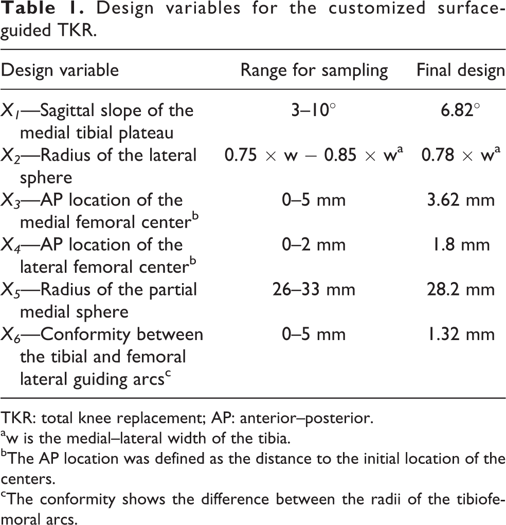
TKR: total knee replacement; AP: anterior–posterior.
aw is the medial–lateral width of the tibia.
bThe AP location was defined as the distance to the initial location of the centers.
cThe conformity shows the difference between the radii of the tibiofemoral arcs.
The tibial insert of this study was designed with a slope on the medial compartment in the sagittal plane. The lower and higher bounds for the slope of the tibia (X1) were defined based on the pooled variance and standard deviation from previous studies on the slope of the medial tibial plateau in healthy knee joints in the AP direction. 18 –22
Based on the surface-guided concept of this TKR, the locations of the lateral sagittal contact points were estimated on the sagittal plane that passed through the center of the lateral tibial plateau. 7 The desired trace of the contact points on the lateral tibial plateau was generated by projection of the estimated points on the sagittal plane onto a sphere named as “lateral sphere.” 7 This sphere had the same center as the center of the medial partial ball and socket configuration and a radius of 0.75–0.85 of the medial–lateral width of the tibia. A fraction of the width of the tibia was considered, because the second design variable (X2) changes the medial–lateral location of the curve of the desired path of the contact points on the lateral tibial plateau. The lower and higher bounds for this variable were set based on the recommended limits for the radius of the lateral sphere by Wyss et al. 5
In this TKR, the line connecting the centers of the medial and lateral condyles represents the flexion–extension (FE) axis. Originally, spheres were fitted to the posterior section of the femoral condyles to determine the locations of the medial and lateral centers. 7 Changing the AP location of these centers (third and fourth design variables) alters the orientation of the FE axis. The lower bound was set at zero, which means no shift of location of the centers. The higher bound for a shift in the AP direction was set considering the limitation in the geometry of the joint extracted from the MRI.
Another design feature for this TKR is the medial partial ball and socket configuration, which means no AP translation of the medial center during flexion or extension of the joint. 5,7 The maximum and minimum radii of the medial sphere (X5) were set based on the largest and smallest sphere that was practically possible to fit the medial femoral condyle.
The role of the tibiofemoral conformity on the kinematic behavior has been studied previously for traditional TKR designs. 8,11 The conformity between the lateral guiding arcs on the femoral and tibial components was considered as another design input variable (X6). No difference between the radii of the tibiofemoral guiding arcs or full conformity was considered as the lower limit. The higher bound of this variable was set based on the geometry of the joint from MRI data and previous design iterations.
Latin hypercube sampling (LHS) method was used to generate 30 randomized designs of the femoral and tibial components based on the input design variables. LHS as a stratified sampling methodology provides uniform coverage of the sample space with a smaller sample size than the one required for the traditional Mont Carlo approach. 13,23 A confidence coefficient of 0.9 24 was used to determine the sample size, which was used along with the upper and lower bounds for each variable (Table 1) to generate different combinations of geometric design variables.
The practically acceptable surface-guided TKR designs were chosen based on the requirements of the design concept and the limitations of the joint geometry extracted from the MRI. 7 For each design candidate, a cycle of deep squatting (reaching up to 140° of flexion) was virtually simulated in MSC.ADAMS (MSC Software corporation). The deep squatting was chosen since for activities like kneeling, gardening, and sitting cross-legged, such range of flexion of the knee joint is required. 25,26 Also, it is reported that patients with traditional knee replacements experience limitation in performing high flexion activities such as squatting and kneeling. 27
This simulation consisted of the CoCr femoral component in contact with an ultrahigh molecular weight polyethylene tibial insert. The boundary condition was such that the femur was only free to rotate around the FE axis, while the tibial insert was free to move in the transverse plane.
7
The tibial axial load and FE angle profiles during a cycle of deep squat were implemented from the study of Smith et al.
28
A contact function named “impact” in MSC.ADAMS with a coefficient of friction of 0.04 between the tibiofemoral articulating surfaces was applied. Such a friction coefficient is in agreement with the reported magnitude of friction between CoCr and PE in the literature.
29
In this simulation, it was assumed that cruciate ligaments were resected, but the influence of the collateral ligaments was modeled as nonlinear spring functions of force elements paralleled with a damper.
The PCA as described by Fitzpatrick et al.
13
was applied to a matrix of variables constituted from six input parameters and the corresponding kinematic output measures for all trials. In this matrix, each row represented the data from a virtual simulation of one design candidate, where the first six elements were the input variables (Xi) and the remaining were the 100 increments of the kinematic measures (Yi). Next, the correlation coefficient matrix was calculated for the matrix of variables, which showed the correlation between all of the 306 variables (inputs and outputs). The PCA based on eigenvalue and eigenvector calculation was used to determine modes of variations in a data set, according to the algorithm described by Fitzpatrick et al.
13
and Laz et al.
23
The matrix of eigenvectors, which is also called the “loading” matrix
30
or the matrix of the principal components, shows the orthogonal directions sorted based on the amount of variance in each direction. Therefore, the first principal component is the line where there is most of the variance. The eigenvalues of the matrix of the correlation coefficients represent the amount of the variance in each direction or principal component of the data set.
13
The combination of variables (inputs and outputs) weighted by the eigenvectors of the correlation matrix determines the principal component score (F)
13,13,30
(equations (1) and (2)). Abdi and Williams
30
described these scores as the projection of the original variables for each observation onto the direction defined by the principal components.
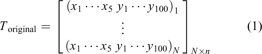

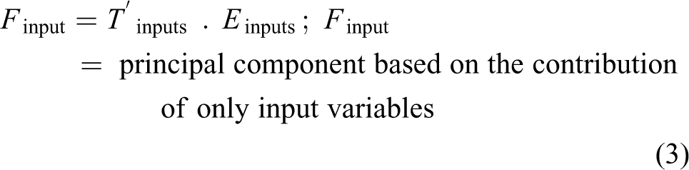
where N is the number of the trials or design candidates, n is the total number of input and output variables (306), and E is the matrix of the eigenvectors of the correlation matrix for the T original. Therefore, new sets of output variables (“F” or principal component scores) were generated, which were mapped from the original variables including all input and output parameters. A traditional correlation analysis was then performed to define the correlation coefficient (r) between the input design variables and the new set of variables (principal component scores). The squared coefficient (r2) determines the proportion of the change of the variables at each mode of variation; therefore, r2 was also used as a criterion to interpret the PCA results. In addition, the percentage of the contribution of each design variable in the input loading matrix of the principal component score (equation (3)) was computed.
The effect of the changes in principal component values on the output was also analyzed by adding two times the standard deviation of the principal component scores for all trials to the computed values of “F” from PCA. Based on the new set of scores, the input and output variables were determined and compared with the original outcomes.
Analytical study on optimization
The objective of this analytical study was to determine a combination of geometric design variables that results in optimum kinematic performance. Therefore, an objective function was derived considering the overall agreement between the kinematic measures from a virtual simulation of deep squatting and those that are expected from a normal healthy knee. The kinematic measures were the estimated tibial IE rotation angles and femoral AP displacement of the medial and the lateral centers of the surface-guided TKR candidates generated previously for PCA. The kinematic outcomes were recorded for 100 intervals during a cycle of deep squatting with heels down. The objective function was defined as the sum of the normal root mean square errors (NRMSE) between IE and AP measurements and the design target as well as the normalized error in the range of IE rotation of the TKR (Equation (4)).

The normalized error was computed relative to the range of the measured IE angles or the AP displacements (the maximum value minus the minimum value). The difference between the expected range of IE rotation and the outcome of the simulation (NEIE) was normalized with respect to the target range of IE rotation.
Results
Principal component analysis
LHS resulted in 23 TKR design candidates that were practically acceptable for further analysis based on the requirements of the surface-guided tibiofemoral design concept. 5,7 Figure 2 shows the outcomes of the virtual simulation (IE rotation of the tibial insert and AP displacements of the medial and lateral femoral condyles) for four different candidate TKRs.

Kinematic outcomes from the virtual simulation of four candidate TKRs. Positive IE value means internal rotation of the tibial insert, and positive AP translation of the femoral centers means movement in the posterior direction. In the graph for the AP translation of the femoral condyles, the green curves show the results of the medial condyle. TKR: total knee replacement; AP: anterior–posterior; IE: internal–external.
PCA results show that the first three principal components accounted for 87% of the total variation with the first three eigenvalues having 58%, 22%, and 7% contribution in the cumulative variability, respectively (Figure 3). Therefore, the first three modes of variation were considered for further analysis of the influence of the input design variables on the variations in the kinematic measures.
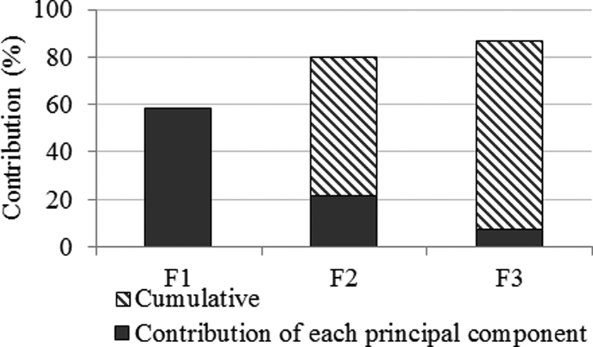
Contribution of the first three principal components in total variations.
The input loadings or the input part of the eigenvector components (columns of the matrix E in Equation (2)) indicate the contribution of each design variable in the input principal component (F input). Based on Figure 4, the AP location of the lateral center (X4) had the largest weight. Three input variables almost evenly contributed to the second mode of variation: radius of the partial medial sphere (X5), AP location of the lateral center (X4), and the sagittal slope of the tibia medial plateau (X1). For the third input principal component, the radius of the lateral sphere (X2) had the largest contribution, and the AP location of the lateral center (X4) was the second contributing factor.

Contribution of design variables in the input principal component.
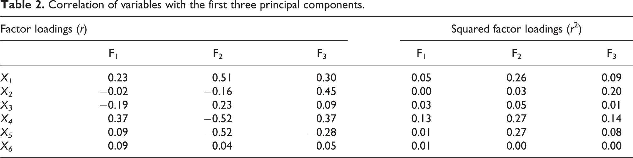
Further study on the correlation between the input design variables and the principal component scores also highlighted the significance of the AP location of the center of the lateral femoral condyle. This design variable was correlated with the first three modes of variation (Figure 5 and Table 2).

Correlations of the geometric design variables with (a) first and second principal components; (b) second and third principal components.
Correlation of variables with the first three principal components.
As the circle of correlation (Figure 5) demonstrates, the first mode of variation was mostly correlated with the changes in the AP location of the center of the lateral femoral condyle (X4) and the sagittal slope of the medial tibial plateau (X1).The correlation between the first mode of variation and the radius of the lateral sphere (X2) and the AP location of the center of the medial femoral condyle (X3) were in contrast with the correlation between the first principal component and the rest of the design variables.
For the second mode of variation, a similar correlation was found with the sagittal slope of the medial tibial plateau (X1), the AP location of the lateral femoral center (X4), and the radius of the medial sphere (X5). However, there was an inverse correlation with the radius of the medial sphere and the AP location of the lateral femoral center. The circle of correlation for the third principal component demonstrates that the radius of the partial medial sphere (X5) was in contrast with all other variables, while the radius of the lateral sphere (X2) was the most correlated parameter. The conformity between the tibial and femoral lateral guiding arcs (X6) was, in fact, the design variable with a small correlation coefficient (r < 0.1) for all first three modes of variation.
Analysis of the kinematic outcomes shows that perturbation in the first principal component resulted in a decreased range of tibial IE rotation, along with posterior displacement (maximum of 5 mm) of the medial femoral condyle during early flexion of the knee. The second mode of variation mostly associated with an increase in the range of IE rotation of the tibia and a maximum of 8 mm anterior translation of the medial center on the tibia (Figure 6).
The influence of changes in modes of variations of parameters on kinematic performance (+2 times of the standard deviation of the PC (Principal Component) scores for the first three modes of variation was considered).
Analytical optimization
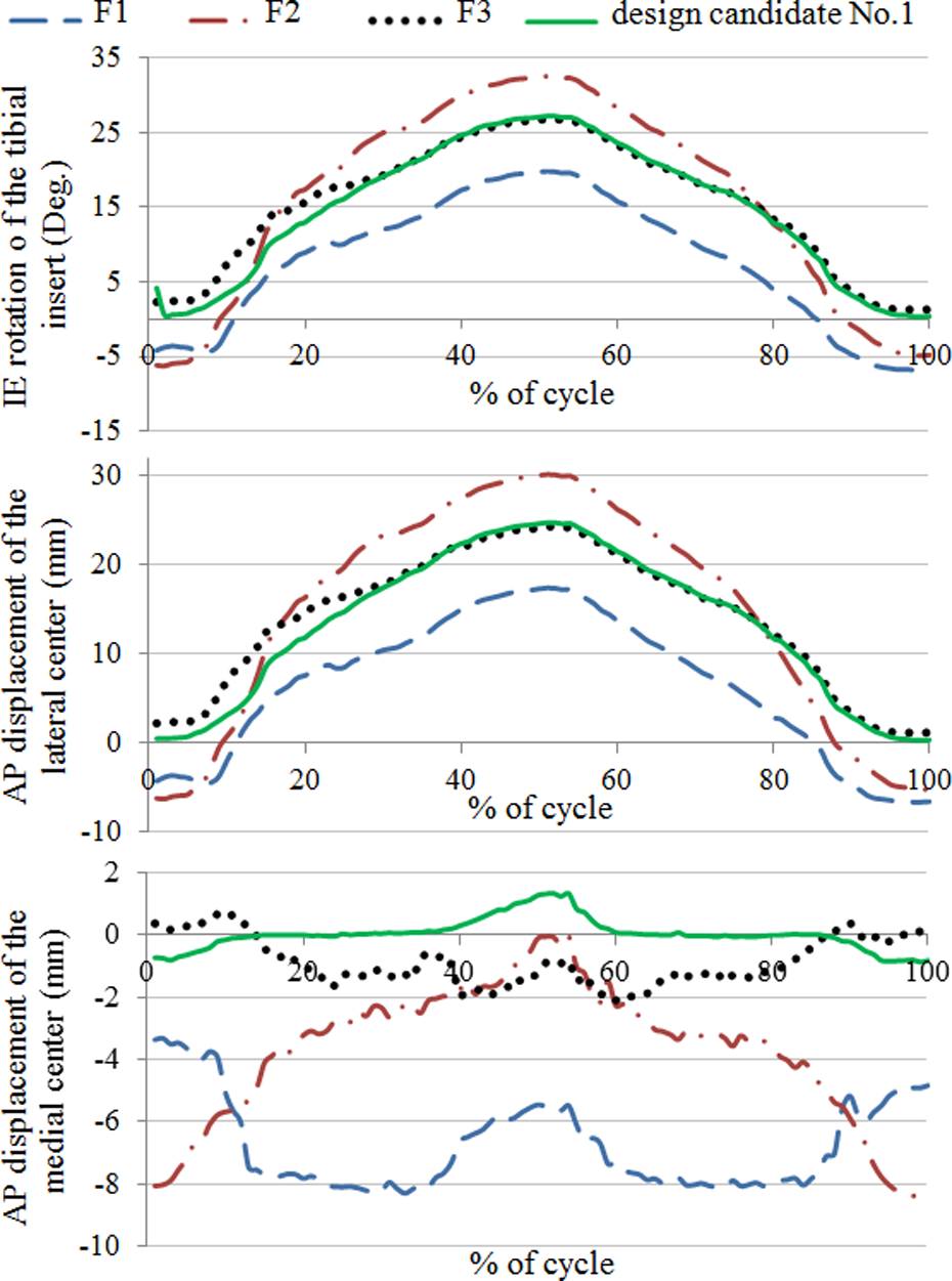
The analysis of the overall error (equation (4)) for the 23 candidates of the TKR designs resulted in the combination of the geometric design variables that provided the best kinematic performance with the minimum overall error (Figure 7). This design followed the target pattern of motion as the knee bent to a deep flexion angle of 140 degrees, with a 23° of the tibial internal rotation angle and an overall error of 33%. The normalized root mean square error between the IE rotation angle of the TKR with the best performance and the design target was 2.7%, while the maximum deviation of 2.75° occurred during mid-flexion angles (Figure 7). There was only 1.2 mm AP displacement of the medial center through a cycle of squatting with normalized RMSE of 28%.

Kinematic outcomes of the surface-guided TKR with the least overall kinematic error in comparison to the design target. TKR: total knee replacement.
Discussion
The influence of the geometric design variables on the kinematic performance of TKR has been a subject of studies of the optimization of the traditional TKR designs. 8,11 This study first investigated the influence of major design variables of a customized surface-guided TKR on kinematic outcomes by PCA combined with virtual simulation of deep squatting. The kinematic performance was quantified by IE rotation angle of the tibial insert and AP displacement of the medial and lateral centers of the femoral condyles that were recorded for 100 increments throughout one cycle of squatting. Finally, a combination of design variables with the best kinematic performance was achieved through the analytical optimization process. This approach was based on an objective function of the overall error between measured kinematic results and the design target for the kinematics.
The traditional sensitivity analysis based on the linear correlation between input and output variables does not consider the influence of input and incremental output parameters altogether. 9 In the current study, the average of the correlation coefficient between each input geometric design variable and all increments of the output measures were determined to run a traditional sensitivity analysis. The results showed that the IE rotation of the tibial insert of the surface-guided TKR was sensitive to the initial AP location of the lateral femoral center (X4) with r > 0.4. The second critical parameter was the radius of the partial medial sphere (r > 0.3). On the other hand, the AP displacement of the medial center was mostly sensitive to the sagittal slope of the medial tibial plateau (r > 0.39). The PCA over the total input and output variables also determined the AP location of the lateral center of the femoral condyle as the most contributing factor in the first mode of variation and as the second correlating variable with the second and third principal components. According to the traditional sensitivity analysis, the radius of the lateral sagittal sphere (X2) was among the variables with less correlation with the kinematic outcome measures (r < 0.2). The PCA, in contrast, showed that it is the variable with the highest correlation with the third mode of variation.
The PCA was repeated to evaluate the relationship between input design variables and each of the outcome measures individually. Similar to the overall PCA, the analysis based only on the IE rotation of the tibial insert emphasized the influence of the AP location of the lateral center (X4) on the first mode of variability in IE rotation (r = 0.54). The second principal component based on IE rotation as the only performance measure was inversely correlated with the radius of the medial sphere (X5). It is in agreement with the overall PCA; however, for the third mode of variation in the IE rotation, the results were different from analysis based on combined kinematic measures. The third principal component attributed to a combination of the sagittal slope of the medial tibial plateau (X1) and the AP location of the lateral center (X4) with r = 0.4. PCA over the matrix of the input variables and the incremental measure of the AP displacement of the medial center resulted in quite different loadings for the first principal component in comparison to the overall PCA. It showed that the first mode of variation in the AP translation of the medial center was influenced by the sagittal slope of the medial tibial plateau (X1) and the radius of the lateral sagittal sphere (X2). It is, however, in agreement with the traditional sensitivity analysis. These results show how the assessment of the combined outcome measures identifies the interrelation between measures and specifies the overall influence of the input variables.
Based on the combination of all input design variables and outcome performance measures, the AP location of the lateral femoral center was a critical parameter. This variable was correlated with the posterior translation of the medial side during early flexion and causing a limitation on the range of the IE rotation of the tibial insert. Furthermore, a combination of the slope of the tibial insert, the radius of the partial medial sphere, and the AP location of the lateral femoral center contributed to the paradoxical anterior translation of the femoral condyles, as the surface-guided TKR bends to deep flexion angles. Fitzpatrick et al. 9 also reported a strong correlation between design parameters (radius of the posterior section of the femoral condyle and the slope of the tibial insert) with the tibiofemoral IE rotation and AP displacement during a cycle of squatting. Ardestani et al. 14 used a sensitivity index based on input principal component and the overall scores for the kinematic performance of a cruciate retaining TKR. They concluded that range of IE rotation of the tibial insert was sensitive first to the femoral posterior radius and to a lesser degree to the tibial posterior and anterior radii.
The final design with the best kinematic performance reached deep flexion angles (around 140°) following a close to design target pattern of motion. The range of flexion of the TKR gained by the initially designed customized surface-guided TKR 7 was 120°; therefore, there is about a 17% increase in the range of motion achieved through the parametric optimization process. During the flexion phase, the designed TKR experienced less than 1 mm anterior displacement of the medial femoral center on the tibial component, while the lateral condyle moved 21 mm in the posterior direction and the tibia rotated 23° internally. Studies on normal healthy knee kinematics reported a similar range of IE rotation for deep flexion of the joint. 25,31 –33 Moro-oka et al. 25 showed that the internal rotation of the tibial component for flexion angles above 80° is caused by posterior translation of the lateral compartment pivoting around a medial center. They reported 30 ± 2° of internal rotation of the tibia for the squatting activity with flexion up to 130°. 25 Hamai et al. 33 similarly showed a medial center of IE rotation during deep flexion, while the femur reached 30° of external rotation with 150° flexion. Leszko et al. 31 also described the motion of the femoral condyles during deep knee bending as posteriorly rolling and spinning of the lateral condyle throughout flexion of the joint up to 120°. However, they reported rolling of both condyles for flexion beyond 120°. 31 The surface-guided TKR of the current study is based on pivoting of the lateral condyle around a medial center, which is in fact reported as a successful design concept for TKRs in the literature. 34,35
The LHS method that was used for this study is reported to be successful in generating a dense uniform arrangement of variables with a relatively small sample size. 9 However, one limitation of the current study is the limited number of design candidates due to the cost of the design process and computation. The chance to achieve an optimum design increases with more design candidates. The combination of the current sampling approach and a systematic optimization method could also give the globally optimized design. Furthermore, considering other variables for the PCA such as the alignment of the components, balancing of the ligament forces, or the loads due to different activities could improve the interpretations about the effective parameters on the performance of the designed TKR.
Conclusions
This study showed that in the design of the customized surface-guided TKR, the location of the femoral lateral center, which affects the orientation of the FE axis, is of great importance. To a lesser extent, the sagittal slope of the medial tibial plateau and the radius of the medial partial ball and socket configuration affect the kinematic performance. The analytical approach was successful in defining the combination of design variables, which creates the TKR with the best kinematic performance in comparison to the design target. The virtual simulation of the optimized surface-guided TKR provides a close to the target pattern of motion during simulated deep squatting activity. The design target is, in fact, consistent with the reported normal knee joint kinematics.
Footnotes
Declaration of conflicting interests
The author(s) declared no potential conflicts of interest with respect to the research, authorship, and/or publication of this article.
Funding
The author(s) disclosed receipt of the following financial support for the research, authorship, and/or publication of this article: This work was supported by the DePuy Synthes and the University of Manitoba.