
Abstract
Objective:
To compare construct stiffness of cortical screw (CS)-rod transforaminal lumbar interbody fusion (TLIF) construct (G2) versus pedicle screw (PS)-rod TLIF construct (G1) in the standardized porcine lumbar spine.
Methods:
Six porcine lumbar spines (L2–L5) were separated into 12 functional spine units. Bilateral total facetectomies and interlaminar decompression were performed for all specimens. Non-destructive loading to assess stiffness in lateral bending, flexion and extension as well as axial rotation was performed using a universal material testing machine.
Results:
PS and CS constructs were significantly stiffer than the intact spine except in axial rotation. Using the normalized ratio to the intact spine, there is no significant difference between the stiffness of PS and CS: flexion (1.41 ± 0.27, 1.55 ± 0.32), extension (1.98 ± 0.49, 2.25 ± 0.44), right lateral flexion (1.93 ± 0.57, 1.55 ± 0.30), left lateral flexion (2.00 ± 0.73, 2.16 ± 0.20), right axial rotation (0.99 ± 0.21, 0.83 ± 0.26) and left axial rotation (0.96 ± 0.22, 0.92 ± 0.25).
Conclusion:
The CS-rod TLIF construct provided comparable construct stiffness to a traditional PS-rod TLIF construct in a ‘standardized’ porcine lumbar spine model.
Introduction
The merits of minimally invasive spine surgery had led to its popularity in recent times. Its advantages include preservation of the multifidus muscle integrity, 1,2 faster immediate post-operative recovery, less post-operative pain as well as less blood loss. 3 It has also been shown to have less tissue destruction with lower blood levels of inflammatory markers such as IL-6 and IL-8. 4 However, the placement of the minimally invasive percutaneous pedicle screw (PS) carries a significant rate of screw malposition, neural structure injury and revision surgeries. 5 Insertion of percutaneous screw in this manner is also dependant on fluoroscopy, and the deleterious effects of radiation on surgeons have been shown. 6,7 Minimally invasive decompression is also reliant on a variety of bone graft substitutes, which would increase the cost of surgery. The efficacy of stand-alone bone graft substitutes for fusion remains debatable. 8 –10
An alternative method to insert screws to the spine is the cortical screw (CS) technique. In this technique, the entry point is more caudal and midline compared to the PS and aimed cranially and slightly divergent. As a result, the size and length of the screws are generally shorter and thinner than the ones used for conventional PSs. However, they do have more cortical bone purchase. The effect of these changes on the fixation stiffness is not well studied at the moment. The introduction of the new cortical trajectory screw technique allows surgeons to reap the benefit of minimally invasive spine surgery and at the same time maintain the safety of screw insertion. A mini open approach in insertion of CS technique also allows harvesting of local bone graft to augment fusion during surgery. There have been one publication on the biomechanical properties of CS constructs but this study was performed on non-standardized cadaveric models. 11 The purpose of this study is to compare the construct stiffness of the CS-rod construct versus the PS-rod construct used in transforaminal lumbar interbody fusion (TLIF) in a standardized porcine animal model.
Materials and methods
The institution ethical committee board has approved this study. Six fresh porcine lumbar spines (L1–L6) were used with the mean age of 180.2 ± 1.7 days and mean weight of 106.4 ± 3.8 kg. All the specimens were healthy pigs, obtained from a single farm, with similar diet and butchered for the food industry. The specimens were randomized according to the order of procurement, and plain radiograph was done to rule out any obvious bony abnormalities such as cysts or fractures.
The lumbosacral spines were harvested through the posterior approach and disarticulated from L1 vertebra to L6 vertebra. All the spines were stored frozen at −20 °C. Before testing, the spines were thawed for 4–5 h in normal saline bath under room temperature and carefully cleaned free of musculature, leaving the osteoligamentous tissues without damaging any ligaments, discs or joint capsules. The lumbar spines were separated into two different functional spine units (FSUs), that is, L2/L3 and L4/L5. The total of 12 specimens was grouped into two different groups (PS-rod TLIF construct and CS-rod TLIF construct) with six FSUs in each group. The FSU was alternated between groups (Figure 1).

Study protocol and characteristic of test porcine subjects.
The FSUs were divided into the following groups: (1) intact FSU (all groups), (2) FSU with bilateral PS TLIF construct (CD HORIZON® LEGACY™ Systems; Medtronic, Memphis, TN, USA) + bilateral total facetectomies and interlaminar decompression + interbody cage (CAPSTONE® Polyetheretherketone, PEEK Spinal System; Medtronic, Memphis, TN, USA; group 1) and (3) FSU with bilateral CS TLIF construct (CD HORIZON SOLERA™ Systems; Medtronic, Memphis, TN, USA) + bilateral total facetectomies and interlaminar decompression + interbody cage (CAPSTONE Polyetheretherketone, PEEK Spinal System; Medtronic, Memphis, TN, USA; group 2). The PS used was multiaxial screws, 5.5 mm × 35 mm, and CS was also multiaxial screws, 4.5 mm × 20 mm. The CS and PS with slight variation in the design and dimensions were chosen based on the recommendation of the technical guide. The interbody implant selected was CAPSTONE Polyetheretherketone, PEEK, cage size 8 mm × 32 mm (Figure 3).
Each vertebral body of the FSU was centred on a custom-made jig and secured firmly. This was done by passing six 1.8 mm K-wires and three 2 mm screws into the vertebral body through the custom jig and embedding the body wire and screws in plaster (AOP 222; Asian Online Plaster, Thailand; Figure 2).
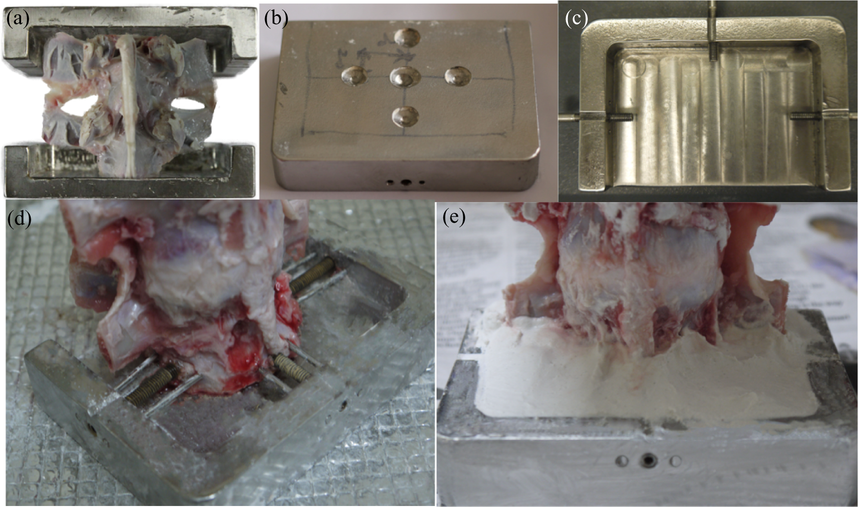
(a) Lumbar porcine functional unit secured with custom made jig. (b) Upper plate of jig with indentation for Instron testing. (c) Lower plate with bolts to secure specimen. ((d) and (e)) Specimen after being secured with bolts, pins and plastered.
The FSUs were first tested in intact condition for both groups to determine the inherent motion property of the intact specimens. This was followed by bilateral total facetectomies, interlaminar decompression and instrumentation of the FSU. The CSs were inserted at the bisection of a horizontal line through the inferior aspect of the transverse process and a vertical line 3–5 mm medial to the lateral edge of the pars and directed 20° in a medial-to-lateral direction and 30–45° from a caudal-to-cephalad direction. The entry point for PSs was at the confluence of the pars interarticularis and the mamillary process, which intersects a horizontal line along the mid of the transverse process . After removal of the disc and endplate preparation, the cage was inserted. The final positions of the screws and cage are checked with fluoroscopy in anteroposterior and lateral views (Figure 3).

Comparison between PS construct and CS construct. PS: pedicle screw; CS: cortical screw.
Testing was performed using universal material testing machine (Instron, Canton, Massachusetts, USA – models 3365 and 5848). Load was applied using extension control with load endpoint. Axial rotation was applied by means of a custom jig comprising of pulleys and cable to convert the linear loads to angular loads. Six modes of loading were performed: (1) flexion, (2) extension, (3) right lateral flexion, (4) left lateral flexion, (5) right axial rotation and (6) left axial rotation. All except the right and left axial rotation was performed using the Instron 3365 with a 2 kN load cell. Bending moment was achieved by means of offsetting the indenter 2 cm away from the axis of the spine, thus providing a combined bending and axial compression. Precycling was performed with three cycles of 375 N load with a ram speed of 21 mm/min and 60 s hold followed by relaxation to 0 N load before the cycle, to minimize the viscoelastic effect of the specimen. Actual loading was applied at a rate of 21 mm/min with a hold for 30 s at 375 N of load and releasing the load to 0 N for another 30 s. No preload was applied. Axial rotation was applied in a similar manner but using the Instron 5848 using a 2 kN load cell. The ram speed was 105 mm/min with an end point at 75 N.
From the raw data, moment–displacement graphs were plotted using Microsoft Excel 2011 for every direction of displacement before and after instrumentations for all the FSUs. A value of stiffness (in N·m/mm or N·m/°) was calculated from a best-fit linear curve through the slope of the linear portion of the graph (Figure 4). Mean value of stiffness and normalized stiffness was calculated from all the data collected. The formula for normalized stiffness of the construct is as follows:


Example of a load–displacement curve to calculate the stiffness of the construct.
In this study, there was no statistical power analysis performed to validate this sample size but the sample number was consistent with similar published studies and fulfilled the recommendation of standardized testing of spinal implants. 12
Paired two-tailed Student t-tests (SPSS version 22.0) were performed on the reduced data to determine whether fixation constituted a significant increase or decrease in stiffness relative to normal. Independent two-tailed t-tests were also used to compare CS construct and PS construct groups. In all cases, p-values of less than 0.05 were considered significant.
Results
There was no implant failure, for example, loosening or breakage of the screws or rods, and no fractures of the bone noticed in the FSUs after testing. For the stiffness calculations from the best-fit linear curves, the mean of R-squared (R 2) values was 0.99678533 with a standard deviation of 0.00379302.
PS constructs and CS constructs versus intact spine
Comparison between the CS and PS constructs with the intact spine is depicted in Figure 5. The results of the biomechanical test for each motion are described below.
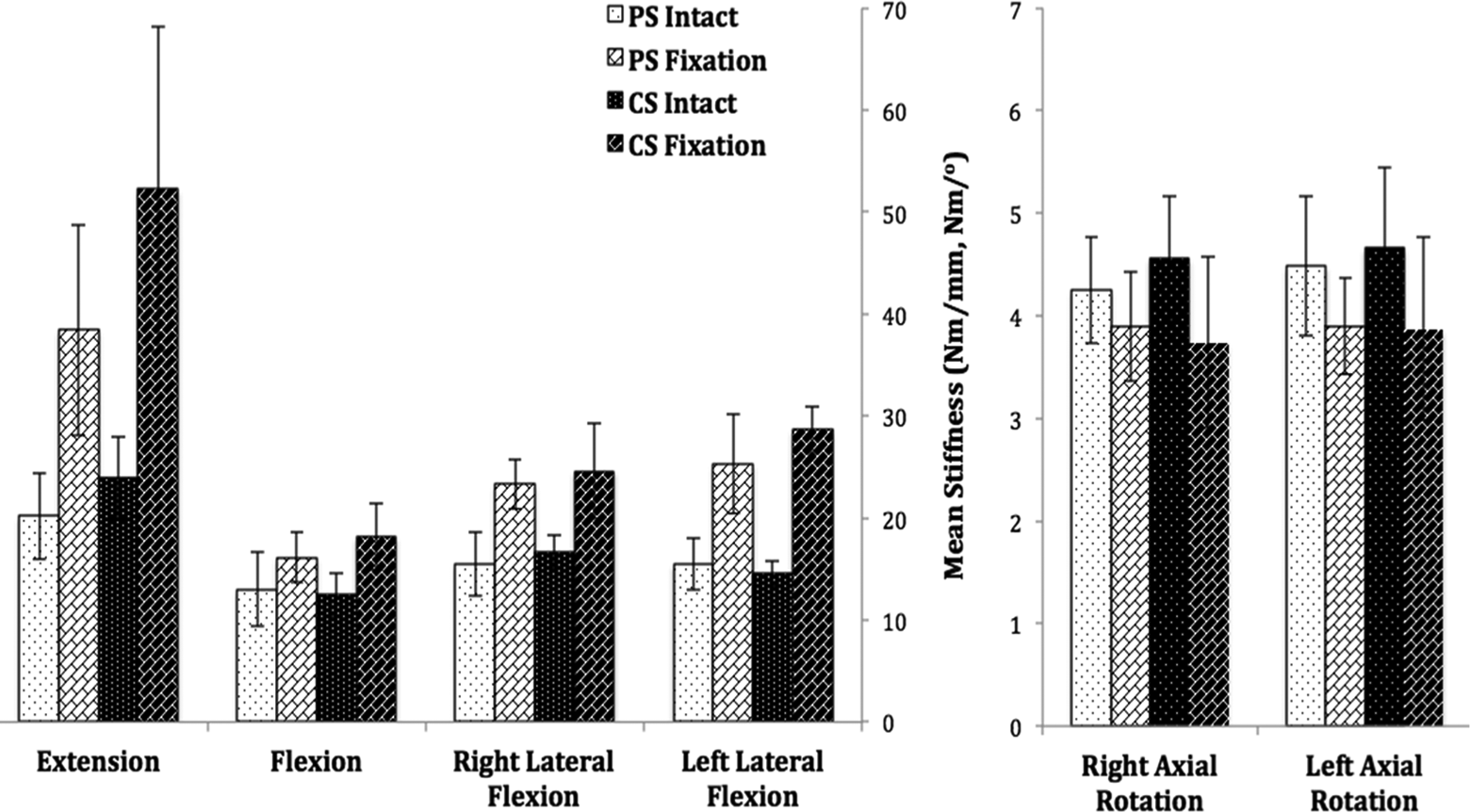
Graph showing the mean stiffness for intact FSU, PS constructs and CS constructs in each loading directions. Error bars show standard deviation for the constructs stiffness. FSU: functional spine unit; PS: pedicle screw; CS: cortical screw.
Extension
For PS constructs, the mean stiffness for intact FSU was 20.21 ± 4.23 Nm/mm and post decompression plus fixation was 38.43 ± 10.32 Nm/mm. For CS constructs, the mean stiffness for intact FSU was 23.92 ± 4.05 Nm/mm and post decompression plus fixation was 52.28 ± 15.87 Nm/mm. Both groups offered a better extension stiffness post fixation as compared to intact FSU, and it was statistically significant (p = 0.002 and p = 0.003, respectively).
Flexion
The average stiffness for intact FSU in PS constructs was 13.01 ± 3.67 Nm/mm and post decompression plus fixation was 16.14 ± 2.42 Nm/mm. For CS constructs, the intact FSU flexion stiffness was 12.46 ± 2.17 Nm/mm and post decompression plus fixation was 18.17 ± 3.24 Nm/mm. Both groups offered a better flexion stiffness post fixation as compared to intact FSU, and it was statistically significant (p = 0.045 and p = 0.010, respectively).
Right lateral flexion motion
For PS constructs, the intact FSU stiffness was 15.51 ± 3.12 Nm/mm and post decompression plus fixation was 23.33 ± 2.44 Nm/mm. For CS constructs, the intact FSU stiffness at right lateral flexion was 16.64 ± 1.63 Nm/mm and post decompression plus fixation was 24.62 ± 4.65 Nm/mm. In both groups, the right lateral flexion stiffness increased significantly after fixations (p = 0.002 and p = 0.012, respectively).
Left lateral flexion motion
For PS constructs, the intact FSU stiffness was 15.47 ± 2.49 Nm/mm and post decompression plus fixation was 25.30 ± 4.85 Nm/mm. For CS constructs, the intact FSU stiffness was 14.56 ± 1.25 Nm/mm and post decompression plus fixation was 28.67 ± 2.33 Nm/mm. In both groups, the left lateral flexion stiffness increased significantly after fixations (p = 0.010 and p = 0.000015, respectively).
Right axial rotation
The average stiffness for intact FSU in PS constructs was 4.25 ± 0.52 Nm/° and post decompression plus fixation was 3.89 ± 0.53 Nm/°. The average value for intact spine in CS constructs was 4.56 ± 0.61 Nm/° and post decompression plus fixation was 3.74 ± 0.83 Nm/°. For both groups, the right axial rotation stiffness post decompression and fixation were less compared to the intact FSU but this was statistically not significant (p = 0.371 and p = 0.086, respectively).
Left axial rotation
The average stiffness for intact FSU in PS constructs was 4.48 ± 0.68 Nm/° and post decompression plus fixation was 3.90 ± 0.47 Nm/°. The average stiffness for intact FSU in CS constructs was 4.66 ± 0.78 Nm/° and post decompression plus fixation was 3.87 ± 0.89 Nm/°. For both groups, the left axial rotation stiffness post decompression plus fixation was less compared to the intact FSU, but it was not statistically significant (p = 0.223 and p = 0.132, respectively).
PS constructs versus CS constructs
Comparison between the CS and PS constructs is depicted in Figure 6. The results of the biomechanical test for each motion are described below.
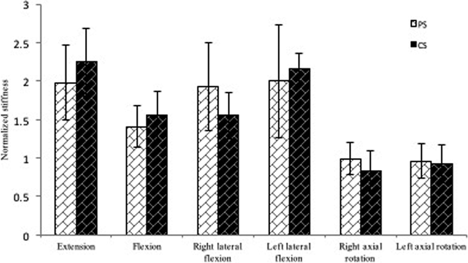
Graph showing the mean normalized stiffness for PS constructs and CS constructs in each loading directions. Error bars show standard deviation for the constructs stiffness. PS: pedicle screw; CS: cortical screw.
Post normalization, CS showed better constructs stiffness than PS constructs in extension, flexion and left lateral flexion. However, PS constructs were stronger in right lateral flexion and both right and left axial rotation. However, the differences between the two groups were not statistically significant (p > 0.05).
Discussion
The advantages of minimally invasive surgery in lumbar degenerative diseases have been well reported in the literature. 13 –15 This technique has been shown to provide faster post-operative recovery, less post-operative pain as well as less blood loss. 3 In addition, minimally invasive surgery had been shown to have a lower risk of infection 16 and to have better overall clinical results. 14,17
An important surgical technique in the armamentarium of minimally invasive spine surgery is the minimally invasive transforaminal interbody fusion technique (MIS-TLIF). Since its introduction in the early 2000, the efficacy in achieving the goals of symptomatic improvement in patients with spondylolisthesis or spinal deformity has been shown in various papers. 18,19 Recent papers on 5-year outcomes of MIS-TLIF have further confirmed the efficacy and high union rate of this technique. 14,20
However, MIS-TLIF has its own disadvantages as well. Percutaneous fluoroscopic PS placement, which is mandatory with this technique, has been fraught with significant incidence of PS malplacement with serious clinical complications. 21 –23 This is particularly so at the L5 and S1 pedicle despite bigger pedicle dimension. 24 –27 Another major issue of this technique is the amount of autogenous bone graft available from the surgical site for the fusion process. This has raised concern among surgeons, and nowadays, the majority of surgeons are reliant on bone graft substitutes to promote fusion, that is, recombinant human bone morphogenetic protein-2 (rhBMP). 28
rhBMP usage in TLIF procedures has been widely studied. Currently, its use in TLIF in the lumbar spine is considered an ‘off-label’ indication. There were many complications associated with its use, which include seroma formation, osteolysis and cage subsidence, heterotopic bone formation and radiculitis. 29 –31 Although further refinement of the dosage used in MIS-TLIF procedures has reduced the incidence of such complications, these associated problems still remain a concern for many surgeons embarking on this procedure.
The cortical trajectory PS insertion technique introduced by Santoni et al. 32 and the usage of Midline Lumbar Fusion (MIDLF) cages are an alternative to MIS-TLIF in minimally invasive lumbar spine surgery. In MIDLF procedure, stripping of the attachment of the multifidus is necessary but compared to traditional open TLIF, the attachment of the multifidus to the mamillary process is preserved. Therefore, the amount of collateral damage to the musculature enveloping the spine is significantly reduced. In addition to this, the trajectory of the CS improves the safety of the screw insertion technique without compromising on the strength of the PS. Santoni et al. have shown that the CSs have an increase of 30% in the pullout strength compared to traditional lumbar PSs. 32 However, in the this study, which was performed in cadaveric specimens, there were significant differences with regard to the age of the study subjects and, therefore, similarity in the bone quality of the test specimens cannot be assumed to be the same despite Dual-energy X-ray Absorptiometry (DEXA) scans were performed in these cadaveric specimens. The CS insertion in MIDLF will require less fluoroscopy/radiation as compared to the fluoroscopic guided percutaneous lumbar PSs used for the MIS-TLIF procedure. MIDLF is a mini-open procedure with limited dissection, and this procedure allows surgeons to harvest more autogenous bone graft for interbody fusion as compared to MIS-TLIF. This would lower the cost of the procedure by avoiding the use of bone substitutes as well as rhBMP.
The stability of the CS in a TLIF or Lateral Lumbar Interbody Fusion (LLIF) procedure has also been shown to be equally stable compared to the conventional PSs model. 11
The rational of the current study is to investigate the rigidity of the CS-rod TLIF construct compared to traditional PS-rod TLIF construct in a standardized porcine model. The usage of porcine specimens, which are equal in terms of age and weight, would ensure that the bone quality is comparable. The choice of porcine specimens is due to the similarity of the porcine spine compared to human lumbar spine in dimension as well as facet morphology. However, porcine facets are known to have a hooked morphology. Therefore, in this study, a bilateral facetectomies were carried out to accurately test the stability of the implants construct.
In this study, we have shown that there was no statistical significance between the stiffness between the CS-rod TLIF construct and the PS-rod TLIF in all six planes of testing, that is, (1) flexion, (2) extension, (3) right lateral flexion, (4) left lateral flexion, (5) right axial rotation and (6) left axial rotation. However, it is not surprising to find that intact specimens without instrumentation were found to be stiffer in axial rotation. These findings were attributed to the facet morphology of the porcine specimens, which was mentioned previously.
There are several limitations in this study, which have to be considered before applying the results to actual clinical scenario. First, the testing carried out in this study is an assessment of construct stiffness and not cyclical testing, which will be more representative of real-life loading in the lumbar spine. Second, the ligamentous and disc material property in the porcine specimen also could be different from human subjects. Finally, the fresh frozen nature of the material tested also might have altered the property of the cortical and cancellous bone, and this might affect the actual stiffness of the real construct.
In conclusion, the CS-rod TLIF construct provided comparable construct stiffness to a traditional PS-rod TLIF construct in a standardized porcine lumbar spine model.
Footnotes
Declaration of conflicting interests
The author(s) declared no potential conflicts of interest with respect to the research, authorship, and/or publication of this article.
Funding
The author(s) received no financial support for the research, authorship, and/or publication of this article.